


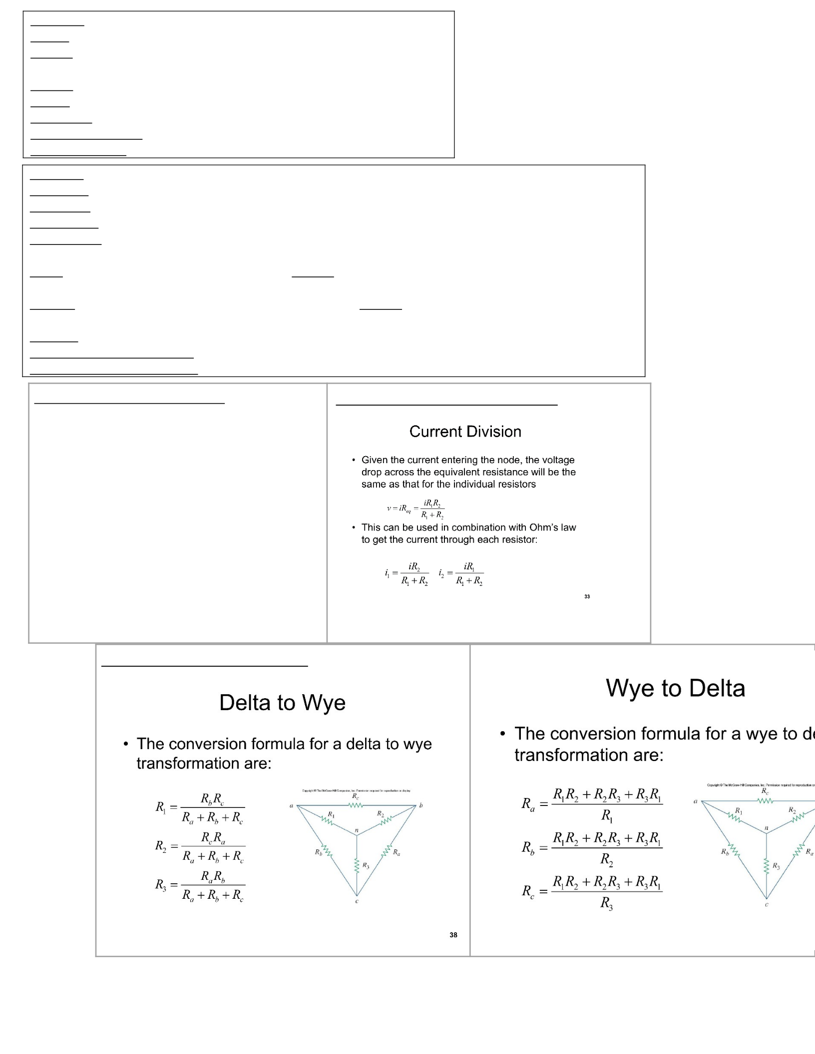
Delta(Δ)-Wye(Y) Transformations:
Chapter 1
Charge=Coulombs(integralofcurrent,areaunderthecurrentcurve)
Current=Coulombs/Second(derivativeofCharge,slopeofcharge,changein
chargeovertime,dq/dt)
Voltage=Joules/Coulomb
Power:P=IV,P=(V)^2/R,P=R(I)^2
Amp-hours=Current*time
Watt-hours (Energy)=Power*time
Watt-hours * $$$=costduetoelectricity
Chapter 2
Resistance=ρ(l/A)p=resistivityconstant,l=length,A=crosssectionalarea
Ohm's Law:V=IR,I=V/R,R=V/I
Short Circuit=0ohms(Resistance),anycurrentcanflowthroughashort
Open Circuit =∞ohms(Resistance),nocurrentcanflowthroughanopencircuit
Branches,nodes,loops:B=L+N-1
Series:TwoElementsshareasinglenode.SameCurrentforallresistorsinseries,differentVoltages(Voltage
Division).
Parallel:TwoElementsconnectedtosametwonodes.SameVoltageforallresistorsinparallel,different
Currents(CurrentDivision).
Linearity:V/I=Rcreatesaperfectlylinearrelationshipforcertaincircuits.
Kirchhoff's Current Law (KCL):Currentin=Currentout
Kirchhoff's Voltage Law (KVL): ThesumofVoltagesaroundaloop=0
Voltage Division (Series Resistors):
TwoResistorsareconsideredinseriesiftheyhave
thesamecurrentpassthroughthem.IfwehaveaVs
andtworesistorsinseries,hereistheequations:
V1=i(R1)
V2=i(R2)
-V+V1+V2=0
-V+i(R1)+i(R2)=0
Thecurrentthroughallresistorsinseriesisthe
same,sousingOhm’slaw:
V1=[(R1)/(R1+R2)]*V
V2=[(R2)/(R1+R2)]*V
V=V1+V2=i(R1+R2)
Current Division (Parallel Resistors):
Chapter 3
Nodal Analysis:Focuseson current flowingintoandoutofeachnode
usingKCL.BecauseV=I/R,weareactuallygoingtofindthenode
voltagesintheend(v1,v2,v3,etc.).
Steps for Nodal Analysis:
1. Identifynodesinthecircuit(usecoloringmethodifnecessary)
2. ApplyKCLateachnode(exceptforthegroundnode)
3. SolvetheKCLequationsusingamatrixtofindtheunknown
nodevoltages.
Tips:
IFthereisavoltagesourcebetweentwononreferencenodes
(v1andv2),thatbecomesasupernode.Treatthesupernodeas
1node,andwriteaconstraintequationusingKCL(current
comingin=currentflowingout,ANDvoltage amount = v1-v2,
usingthe+ontheVsasthepositivenodevoltageand-onthe
Vsasthenegativenodevoltage).
Ifthereisavoltagesource(Vs)betweenanonreferencenode
(V1)andareferencenode(Ground),do[(Vs-V1)/resistance]
IfthereisaVoltageSource(Vs)rightnexttoanonreference
node(v1)anditlookslikeitisthesamevoltage,itprobablyis!
Do Nodal Analysis If the circuit contains:
Manyelementsinparallel
CurrentSources
Supernodes
CircuitswithfewerNodesthanmeshes
IftheNodeVoltageiswhatisbeingsolvedfor
Non-PlanarCircuits
Mesh Analysis:UsesKVLtofindunknown"MeshCurrents"(only
appliesinplanarcircuits).
Steps for Mesh Analysis:
1. Assignmeshcurrentstomeshes
2. ApplyKVLtoeachofthemeshes(loops)
3. Solvetheresultingequationstogetthemeshcurrents
Tips:
ThemeshcurrentsuseKVLcalculatedCLOCKWISEaroundthe
mesh/loop.
IfthemeshcurrentgoesWITHtheVoltagesorce(from-->(-+)
-->),thenthevoltagesourceshouldbenegativeintheKVL
equation.
IfthemeshcurrentgoesAGAINSTtheVoltagesource(from-->
(+-)-->),thenthevoltagesourceshouldbepositiveintheKVL
equation.
IFthereisaresistor bordering twomeshes ,makethe1stmesh
currentyouareworkingonpositiveandtheborderingmesh
currentnegative.
Ifthereisacurrent source isolated toamesh ,thatmesh
current=thecurrentsource.
Ifthereisacurrent source bordering twomeshes ,thatis
classifiedasaSUPERMESH.Fortheconstraintequation,use
themeshcurrentsborderingthecurrentsourceandtheir
directiontodeterminewhichispositiveandwhichisnegative.
Ifameshcurrentisgoingthesamedirectionasthecurrent
source,thenitispositiveintheconstraintequation.Ifamesh
currentisgoingagainstthecurrentsource,thenitisnegativein
theconstraintequation.
AftertheconstraintequationiswrittenfortheSUPERMESH,
youthenREMOVE(createanopencircuit)thewirecontaining
thecurrentsourceandresistoritisattachedto.Then,apply
KVLontheremainingMesh,usingI1andI2accordingly
(whateverresistorsappliedtoI1beforethesupermeshbranch
wasremoved,stillappliestoI1,andviceversaforI2).
Do Mesh Analysis if the circuit contains:
Manyelementsinseries
Voltagesources
Supermeshes
Acircuitwithfewermeshesthannodes
Ifabranch/meshcurrentiswhatisbeingsolvedfor
Chapter 4
Linearity:AsVoltagegoesup,Currentgoesup
proportionally.Theresponseofacircuittoasum of
sourceswillbethesum of the individual responses
fromeach source separately.
Linearity:
V=iR
k(iR)=k(V)
V=(i1+i2)R=(i1)R+(i2)R=V1+V2
Superposition:Iftherearetwo or more independent sourcesthereareThree waysto
solveforthecircuitparameters:NodalAnalysis,MeshAnalysis,Superposition
SuperpositionPrinciplestatesthatthevoltage/Currentthroughanelementina
linearcircuitisthetotal sum of the voltages/currentsthroughthatelement
duetoeachindependentsourceactingalone.
Steps for Superposition:
1. Turnoffallindependentsourcesexceptonesource.Findtheoutput(voltageor
current)duetothatactivesourceusingtechniquesinChapter2/3
2. Repeatstep1foreachoftheotherindependentsources
3. Findthetotalcontribution(voltageorcurrent)byaddingallthecontributions
(voltagesorcurrents)duetoeachindependentsource.
TipsforSuperposition:
Toremoveacurrentsource,replaceitwithanopencircuit(i=0).
Toremoveavoltagesource,replaceitwithashortcircuit(v=0).
Source Transformation:ReplacingaVoltagesource(Vs)inseries
witharesistorRbyacurrentsource(Is)inparallelwitharesistorR,
orviceversa.
Vs=Is*R
Is=Vs/R
Thecurrentsourceisdirectedtowardsthepositiveterminal
ofthevoltagesource
SourceTransformationisnotpossiblewhenR=0orR=∞
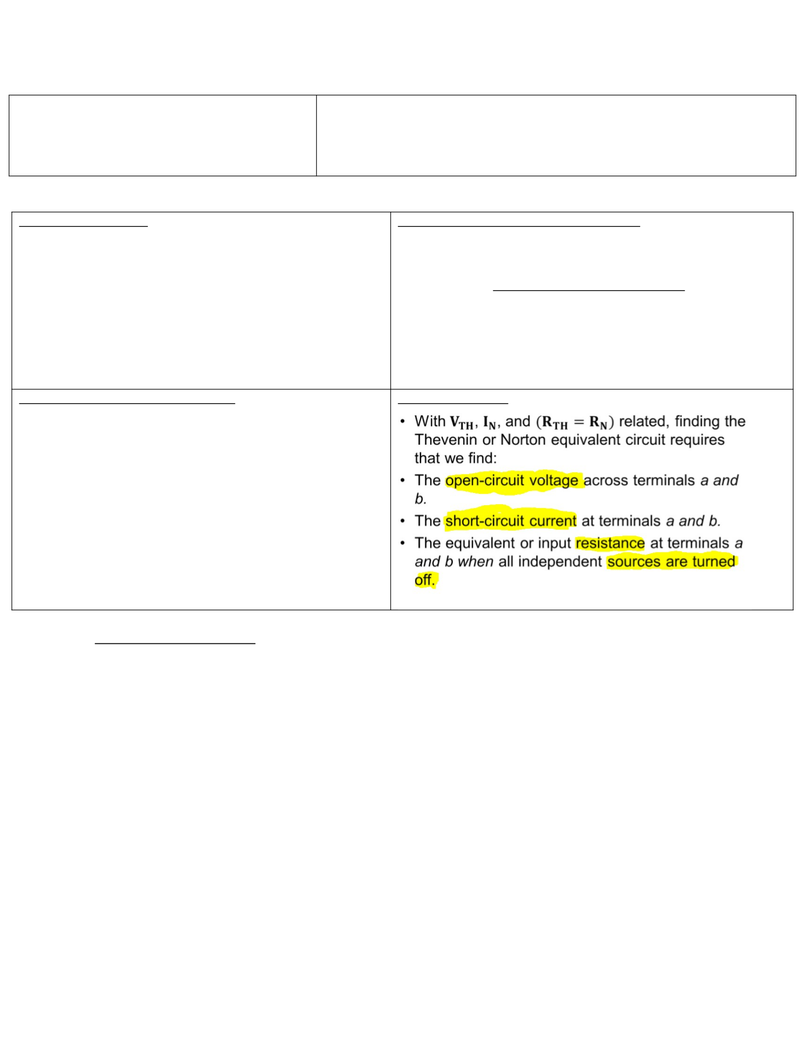
Thevenin's Theorem (Thevenin Equivalents):Whenyouhaveone
variableelementthatyouaretryingtoanalyze,calledtheload.
TheveninVoltage(Vth/Voc)=OpenCircuitVoltage(R=infinite)
TheveninResistance(Rth)=Resistancelookingintoterminalsa
andbwithall independent sources turned off.
TheveninCurrent(Ith/In/Isc)=Vth/Rth=Ith
Useavoltagesourceinserieswitharesistancetoreplace
complicatedlinearcircuits
Itispossiblefortheresultofthisanalysistoendupwithanegative
resistance.Thisimpliesthecircuitissupplyingpower.Thisisreasonable
withdependentsources
Norton's Theorem (Norton Equivalents):SimilartoThevenin’s
theorem,Norton’stheoremstatesthatalineartwoterminalcircuit
maybereplacedwithanequivalentcircuitcontainingaresistorand
acurrentsource.
NortonCurrent(In)=ShortCircuitCurrent(Isc)
NortonResistance(Rn)=TheveninResistance(Rth)
NortonVoltage(Vn)=[Vn=In*Rn]
TheNortonCurrent(In)isfoundbyshortcircuitingthe
circuit'sterminalsandmeasuringtheresultingcurrent.
NortoncurrentisrelatedtoTheveninvoltageandresistance
bysourcetransformation:In=Vth/Rth
Norton vs. Thevenin
Maximum Power Transfer:
P=[(Vth)^2/4(Rth)]
Chapter 5 Concepts
5TerminalsfoundonallOp-amps:
a. Invertinginput
b. Non-invertinginput
c. Output
d. Positiveandnegativepowersupplies
Outputvoltageofanop-ampcanbefoundusingthefollowingequation:Vo=A*Vd=A*(V+-V-)
oAistheOpenLoopGain,whichisdifferentfromtheclosedloopgain.
Feedback:Theoutputoftheop-ampisfedbacktotheinvertingterminal,givingtheop-amp
"NegativeFeedback".
VoltageSaturation:Theoutputvoltageoftheop-ampcannotexceedtheinputvoltages.Therefore,
whenanoutputvoltageshouldexceedthepossiblevoltagerange,theoutputremainsateitherthe
minimumormaximumsupplyvoltage.
Ideal Op-Amps:
oInfiniteOpenLoopGain(A)
oInfiniteInputResistance(Ri)
oZerooutputResistance(Ro)
oZeroinputcurrenttotheinverting/noninvertingterminals(Io)
oOutputcurrentisNOTzero
Inputvoltagesontheinverting/noninvertingterminalsareequal
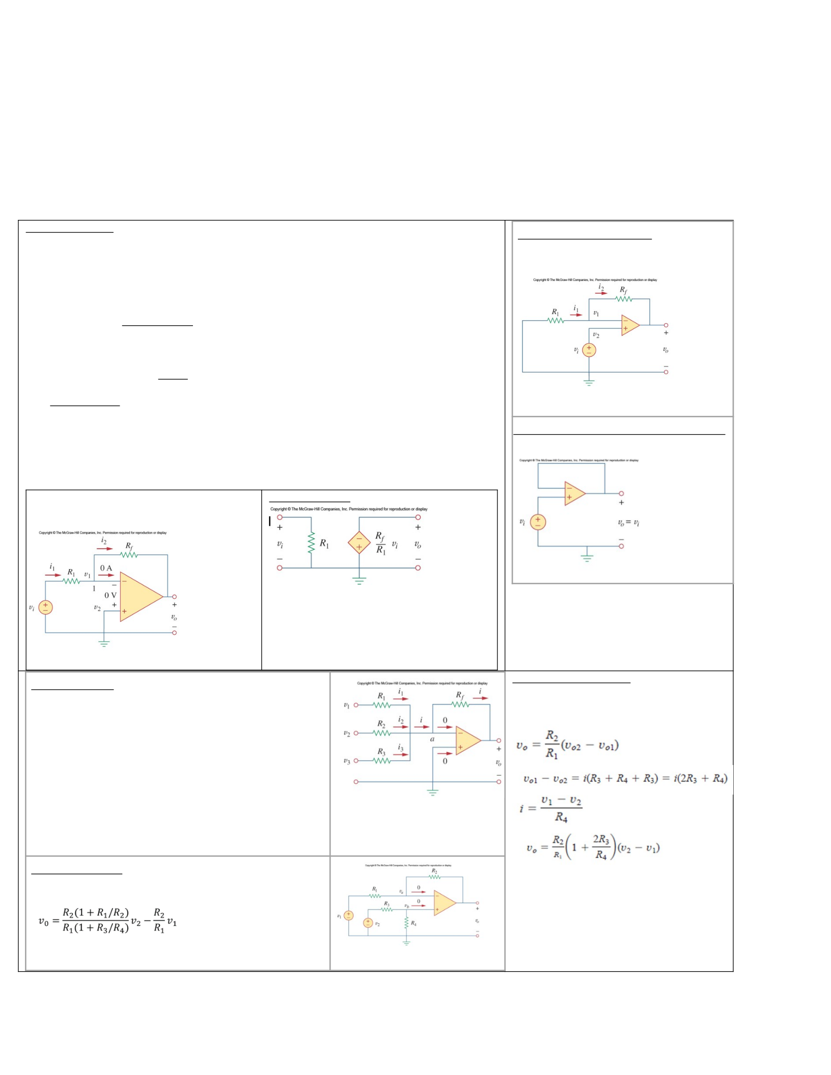
InvertingOp-amp(ideal)
IdealOp-AmpRulesapply
Vo=(-Rf/R1)*Vi
Equivalent circuit:
Non-inverting Op-Amp (Ideal)
IdealOp-AmpRulesapply
Vo=Vi*[1+(Rf/R1)]
Voltage Follower (Ideal, non-inverting op-amp)
Vi=Vo
Summing Op-Amp
Usestheinvertingamplifierandseveralinputs(eachwiththeir
ownresistor),thesummingamplifiercanbeusedtocreatea
simpledigitaltoanalogconverter(DAC).
I1=[(V1-Va)/R1]
I2=[(V2-Va)/R2]
I3=[(V3-Va)/R3]
Ia=I1+I2+I3
Ia=[(Va-Vo)/Rf]
Vo=-[(Rf/R1)*V1+(Rf/R2)*V2+(Rf/R3)*V3]
Difference Amplifier
-Voisproportionaltothedifferencebetweenthetwoinputs.
-Va=Vbduetonegativefeedback.
CommonModeRejection:Adifferenceamplifierrejectsanysignal
thatiscommontothetwoinputs,followingthisequation:
Instrumentation Amplifier
-Places2non-invertingamplifiersbeforethe
differenceamplifiertoincreasetheimpedance
ofthedifferenceamplifier
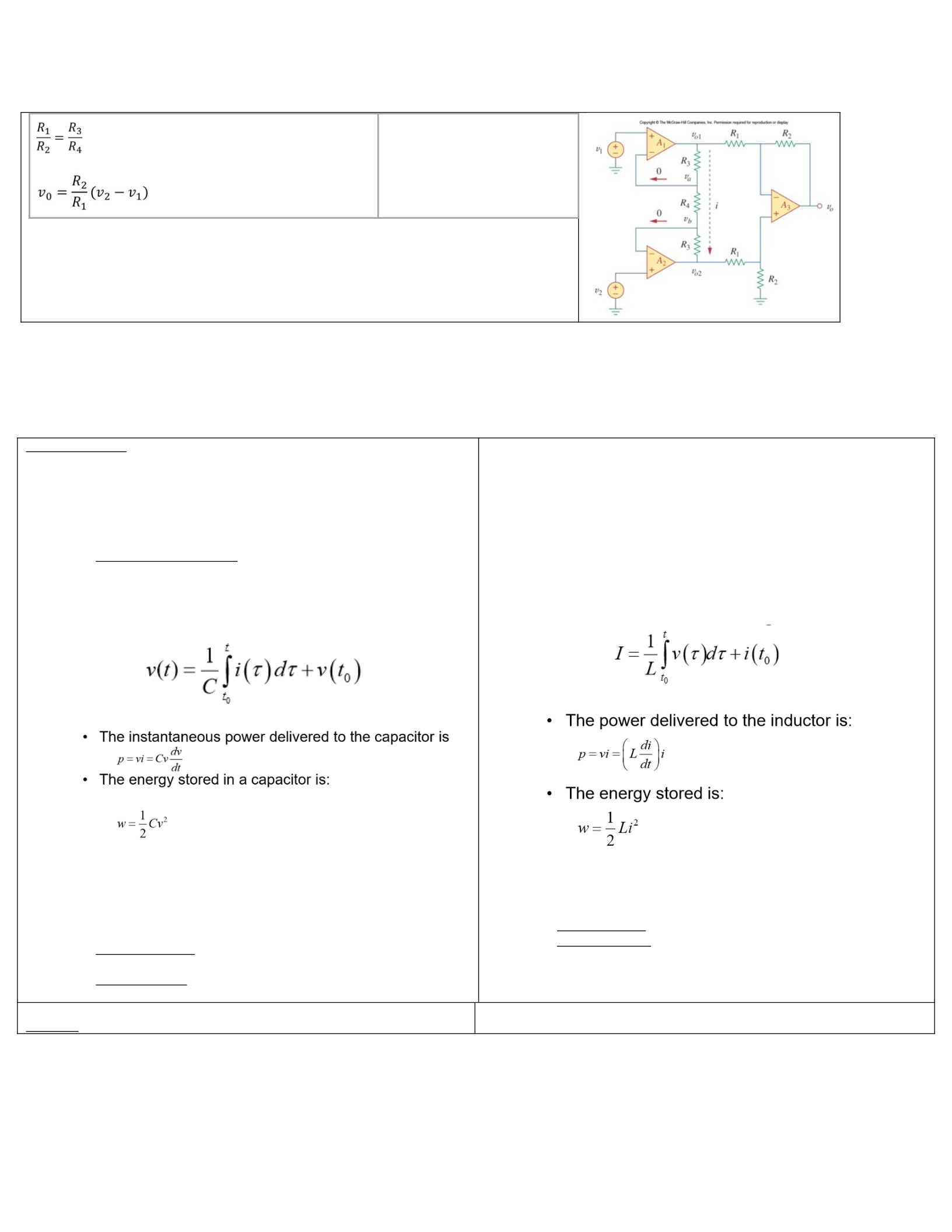
Ifthisconditionistrueforadifferenceop-amp,theoutputisthen:
Chapter 6 Concepts
Capacitors
oCapacitorFormulas:
CapacitanceFormula:C=(E*A)/d
E=permittivityofdialectric
A=crosssectionalareaofplates
D=distancebetweenplates
Chargestoredinacapacitor isequaltothecapacitance*Voltage:q =
C*V
Takethederivativeofthisequationtofindcurrentinacapacitor:I =
C*(dv/dt)
Thisisalsothe"ICE"partofthe"ELITHEICEMAN"acronym
Tofindvoltageinacapacitorduetocurrent:
oCapacitorProperties:
WhenthevoltageisNOTchanging(constant),thecurrentthroughthe
capacitoriszero(opencircuitatDCconditions).
VoltageonthecapacitorplatesCANNOTchangeinstantaneously.
Ifthevoltageonthecapacitordoesnotequaltheappliedvoltage,charge
willflowuntilthecapreachestheappliedvoltage.
Parallel Capacitors: Actlikeseriesresistors,orlikeconductancevalues.
C1+C2+C3=Ceq
Series Capacitors: ActlikeParallelResistors,orlikeconductancevalues.
[(1/C1)+(1/C2)+(1/C3)]^-1=Ceq
Inductors
oInductorformulas:
Forasolenoid,theinductanceformulais:L=(N^2*u*A)/l
U=permeabilityofthecorematerial
N=numberofturnsofthewire
A=crosssectionalarea
L=length
Ifcurrentispassedthroughaninductor,thevoltageacrossitisdirectly
proportionaltotherateofchangeofcurrentflowingthroughit:V =
L*(di/dt)
Thisisthe"ELI"partofthe"ELITHEICEMAN"acronym
Thecurrentstoredinaninductorduetovoltage:
oInductorProperties:
IfthecurrentacrossaninductorisNOTchanging(constant),thevoltage
acrossaninductoriszero(shortcircuitatDCconditions).
ThecurrentthroughaninductorCANNOTchangeinstantaneously.
Series Inductors: Justlikeseriesresistors.L1+L2+L3=Leq
Parallel Inductors: Justlikeparallelresistors.[(1/L1)+(1/L2)+(1/L3)]^-
1=Leq
CombiningOp-amps,Capacitors,andinductors:
Integrator
Differentiator
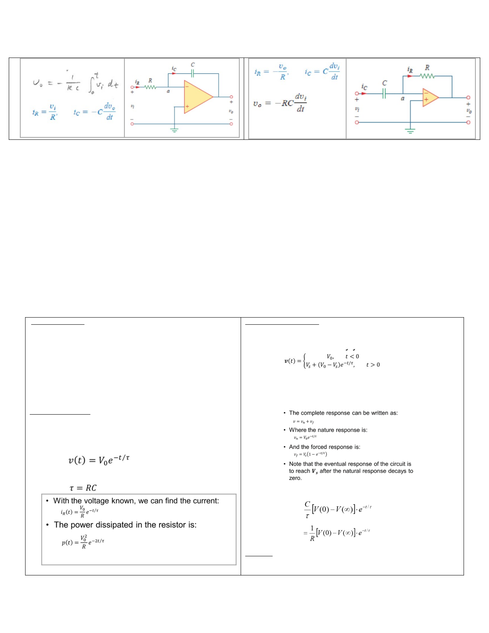
EquationtofindVo:
Chapter 7 Concepts:
First-OrderCircuits(RCandRLCircuits)
CircuitExcitation
NoIndependentSource(NaturalResponse)
oaDCsourceissuddenlydisconnected
oStoredenergyintheCapacitor/Inductoristhen
releasedtothesystemoveraperiodoftime
WithindependentSource(ForcedResponse)
oDC,exponential,sinusoidal.Energyprovidedby
sources
NaturalResponse+ForcedResponse=CompleteResponse
Source Free RC Circuits
Sincewecanassumethecapacitorwasinitiallycharged,att=0theinitial
voltagethroughthecapacitoris:
V(0)=0
Asthecapacitorbeginstodischarge,thenaturalresponsestartstooccur
andvoltagestartstodissipate:
Timeconstant(thespeedatwhichthevoltagedropsto1/eofthe
initialvoltage):
Step response of RC Circuits
WhenaDCsourceissuddenlyappliedtoaRCcircuit,thesourcecanbe
modeledasastepfunction.
Thecompleteresponse:
Thefirstpartisthenaturalresponseofthecapacitor/inductordue
totheenergystoredinit.
Thesecondpartistheforcedresponseduetotheconnected
voltagesource.Vs = V(∞)andVo = V(0)
OnceV(t)isfound,currentcanbefound:
i(t)=
o
o
RL Circuits
oSourceFreeRLCircuits
Currentcannotchangeinstantaneously
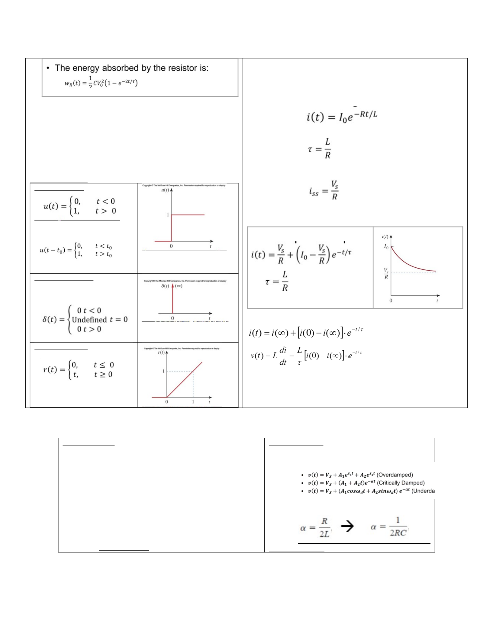
Thekeytoworkingwiththistypeofsituationis:
Startwiththeinitialvoltageacrossthecapacitorandthetime
constantRC.
Withthesetwoitems,thevoltageasafunctionoftimecanbe
known.
Fromthevoltage,thecurrentcanbeknownbyusingthe
resistanceandOhm’slaw.
TheresistanceofthecircuitisoftentheTheveninequivalent
resistance.
Singularity Functions:
Unit Step Function
Theswitchingtimecanbeshiftedto
t=toby:
Unit Impulse Function
Thederivativeoftheunitstep
function
Unit Ramp Function
IntegrationoftheUnitStepFunction
Wearelookingforthecurrentthroughtheinductor
Therefore,wemustdetermineitsvalueasafunctionoftime
Initialcurrentpassingthroughtheinductoratt=0:
I(0)=0
Astheinductorbeginstoreleaseenergyintothesystem,thenatural
responsestartstooccur:
Timeconstant:
oStepResponseofRLCircuits
Steady-statecurrentthroughaninductor:
Currentcannotchangeinstantaneouslythroughaninductor:
i(0+)=I(0-)=Io
Completeresponseofcurrentthroughaninductor:
Chapter 8 Concepts
Second-orderCircuits(RLCcircuits)
oStartbygettinginitialconditionsI(0)anddI(0)/dt(forparallelRLC
circuits,V(0)anddV(0)/dt):
Capacitor:OpenCircuitatlong-termconditions.Voltage
cannotchangeabruptly
V(0-)=V(0+)=Vo
Inductor:ShortCircuitatlong-termconditions.Current
cannotchangeabruptly.
i(0-)=I(0+)=Io
oFigureoutwhichdampingcasethecircuitwillrequire,solve
characteristiceqn.forroots,applythemincorrectformula,solveforI
orV:
Series RLC Circuits:
Parallel RLC Circuits:
AllthesameequationsasseriesRLC,except:
ChangeI(t)-->V(t)
Vs=V(∞)
Change:
Damping Responses:
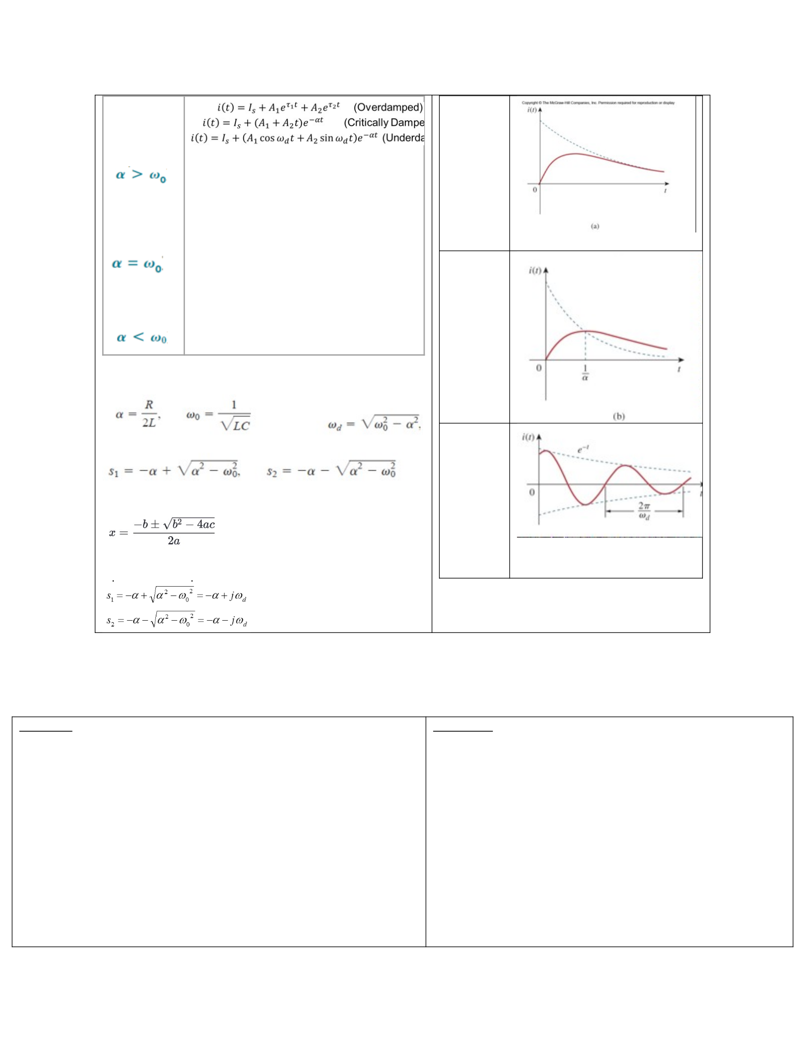
Overdamp
ed(the
rootsare
realand
negative)
Critically
Damped
(rootsare
realand
equal)
Underdam
ped(roots
are
complex)
oDampingfactor,UndampenedNaturalFrequency,damped
naturalFrequency(shownbelowinorder)
oSolutionstocharacteristicequation:
oAlsocanbefoundusingquadraticformula:
oUnderdampedcaseroots:
Overdamped
Critically
Damped
Underdamp
ed
Chapter 9
SinusoidalVoltage:V(t)=Vmsin(ωt± ɸ)
oThefunctionrepeatseveryperiod,oreveryTseconds
oT=2π/ω
oFrequency(Hertz):f =1/T
oAngularfrequency:ω=2πf
Complexnumbers:
oRectangularform:z=x+jy
oPolarform:Z=r<ɸ
oExponentialform:Z=rejɸ
Rectangulartopolar:
r=sqrt(x2+y2)
ɸ=tan-1(y/x)
Polartorectangular:
Chapter 10
StepstoanalyzeACCircuits:
oTransformthecircuittothephasororfrequency
domain
oSolvetheproblemusingcircuittechniques
oTransformbacktotimedomain.
PerformthefollowingasinDC:
oNodalAnalysis
oMeshAnalysis
oSuperposition
oSourceTransformation
oTheveninandNortonEquivalents
oOpAmpAnalysis
X=rcosɸ
Y=rsinɸ
Phasors
oConvertingfromtimedomaintophasor:
V(t)=Vmcos(ωt± ɸ)-->Vm<ɸ
V(t)=Vmsin(ωt± ɸ)-->Vm<ɸ-90°
Currentsworkthesameway,justreplaceVmwithIm.
oPhasorRelationships(ELITHEICEMAN)
Resistors:V=IR
VoltageandCurrentareinphasewitheach
other(0°difference)
Inductors:R=V/I=jωL
ELI-->VoltageLeadsCurrentby90°,orcurrent
lagsvoltageby90°
Capacitors:R=-j/ωC
ICE-->Currentleadsvoltageby90°
oImpedance-->phasorversionofresistance
oAdmittance-->inverseofimpedance,phasorversionof
conductance
oIntherectangularformofImpedance(z=x+jy),thereal
part(x)istheresistance,andtheimaginarypartisthe
reactance(jy)
Whentheimpedanceispositive,it'sinductive(jwl),
whenit'snegativeit'scapacitive(-j/ωC)
oIntherectangularformofadmittance(z=x+jy),thereal
part(x)istheconductance,andtheimaginarypartisthe
susceptance(jy)
Chapter 11
Instantaneous Power :(1/2)VmIm[cos(ɸv-ɸi)+cos(2ωt+ɸv+ɸi)]
oTherateatwhichanelementabsorbspower,orthepoweratanyinstantintime
o1stcosineisconstantpower,2ndcosineissinusoidalpower
Average Power :
o(1/2)VmImcos(ɸv-ɸi)
o***Averagepowerabsorbedbyaninductorandcapacitoriszerowatts.***
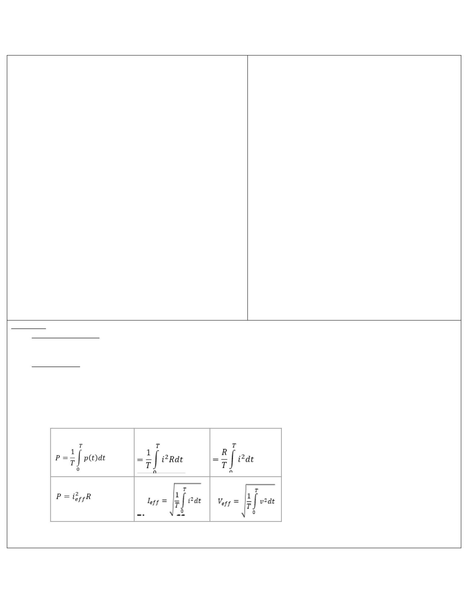
oAveragepowerisalso:
Forperiodiccurrent:
ForDCCurrent:
Resistivevs.ReactivePower
oResistive:Whenɸv-ɸi=0°,thevoltageandcurrentareinphaseandthecircuitispurelyresistive
P=(1/2)VmIm=(1/2)Im2R=(1/2)|I|2R
oReactive:Whenɸv-ɸi=±90°,thecircuitabsorbsnopowerandispurelyreactive
P=(1/2)VmImCos(±90°)=0
MaximumAveragePower
oPmax=(|VTh|2)/(8RTh)
RMS
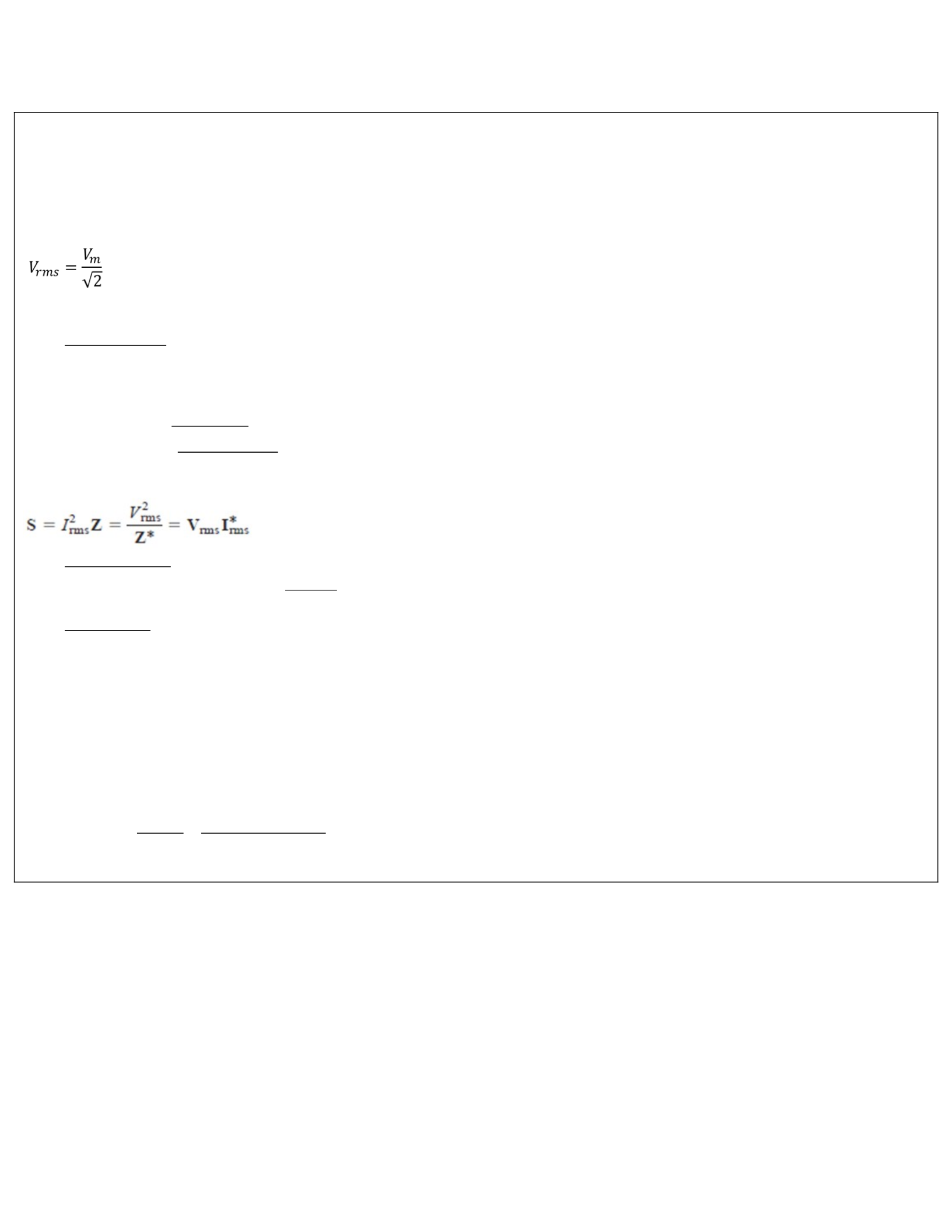
oforasinusoidalwaveform,theRMSvalueisrelatedtotheamplitudeasfollows:
oRMSPowercanbedeterminesfromeitherRMScurrentorvoltage:
P=(IRMS)2R=(VRMS)2/R
Complex Power
oS=(1/2)VI*
I*=complexconjugateofcurrent
oS=P+jQ
P=Real power -->
Scos
(
θv−θi
)
jQ=Reactive power-->
Ssin
(
θv−θi
)
oS=VRMSIRMS*
oS=|VRMS||IRMS|<(ɸv-ɸi)
Apparent power
oTheproductofRMSvoltageandcurrentwillbecalledapparentpower.
|S|=|VRMS||IRMS|=
√
P2+Q2
Power Factor
oP/S=cos(ɸv-ɸi)-->cos-1(P/S)=PowerFactorRatio(between0and1)
P=RealPower
S=Apparentpower
RealPower(P)=ApparentPower(S)*PowerFactor(PF)
PowerFactor=cos(ɸv-ɸi)
Addingacapacitor
oTomitigatetheinductiveaspectoftheload,acapacitorisaddedinparallelwiththeload.
oWiththesamesuppliedvoltage,thecurrentdrawislessbyaddingthecapacitor.
o
C=Qc
ωV rms
2=P
(
tan θ1−tan θ2
)
ωV rms
2

