



PHYS 231 - UNIVERSITY PHYSICS I
- Equilibrium and Elasticity
Question Bank - Set 9
Liberty University
Question 1
Question
A cylindrical steel rod of length Land diameter dhangs vertically from the
ceiling. If the Young’s modulus of steel is Y, determine the elongation of the
rod under its own weight.
Solution
Let’s assume that the density of steel is ρand the acceleration due to gravity is
g.
Step 1: Calculate the mass of the rod. The mass of the rod can be calculated
using the formula:
m=ρ·V=ρ·A·L
where Vis the volume of the rod, Ais the cross-sectional area of the rod, and
Lis the length of the rod.
The cross-sectional area of the rod is given by:
A=πd2
4
Therefore, the mass of the rod is:
m=ρ·πd2
4·L
Step 2: Calculate the force due to the weight of the rod. The force due to
the weight of the rod is equal to the gravitational force acting on it, which is
given by:
F=m·g=ρ·πd2
4·L·g

Step 3: Calculate the stress in the rod. The stress in the rod, σ, is given
by:
σ=F
A=ρ·πd2
4·L·g
πd2
4
=ρ·g·L
Step 4: Calculate the strain in the rod. The strain in the rod, ϵ, is given
by:
ϵ=σ
Y
Step 5: Calculate the elongation of the rod. The elongation of the rod, ∆L,
is given by:
∆L=ϵ·L=ρ·g·L2
Y
Therefore, the elongation of the rod under its own weight is ρ·g·L2
Y.
Question 2
Question
A solid cylinder of radius Rand mass Mis resting on a rough inclined plane
with angle θ. The coefficient of kinetic friction between the cylinder and the
incline is µk. If the cylinder starts to slide down the incline, determine the
acceleration of the cylinder.
Solution
Step 1: Draw a free-body diagram for the cylinder. The forces acting on the
cylinder include the gravitational force (mg) acting downwards, the normal force
(N) acting perpendicular to the incline, the frictional force (fk) acting opposite
to the direction of motion, and the component of the gravitational force parallel
to the incline. Step 2: Break down the gravitational force into components
parallel and perpendicular to the incline. The component of the gravitational
force parallel to the incline is mg sin(θ), and the component perpendicular to the
incline is mg cos(θ). Step 3: Write down the net force equation in the direction
parallel to the incline. The net force in the direction parallel to the incline
is equal to the component of the gravitational force minus the force of kinetic
friction. Therefore, we have:
Ma =mg sin(θ)−fk
Step 4: Express the force of kinetic friction based on the coefficient of kinetic
friction. The force of kinetic friction can be expressed as fk=µkN. And
the normal force, N, can be found by balancing forces in the perpendicular
direction:
N=mg cos(θ)
2

Step 5: Substitute the expression for the force of kinetic friction and the normal
force into the net force equation. Substitute fk=µkNand N=mg cos(θ) into
the net force equation:
Ma =mg sin(θ)−µkmg cos(θ)
Step 6: Solve for acceleration, a. Solving for a, we get:
a=g(sin(θ)−µkcos(θ))
Therefore, the acceleration of the cylinder sliding down the incline is a=
g(sin(θ)−µkcos(θ)).
Question 3
Question
A uniform cylindrical beam of radius Rand length Lis hinged at one end and
propped up by a support at an angle θas shown in the figure below. The beam
has a mass Mand is in static equilibrium. Determine the force exerted by the
support on the beam and the force exerted by the hinge.
mg
NF
θ
M
Solution
Step 1: Draw free body diagrams of the beam and show all forces acting on it.
Step 2: Write down the equilibrium conditions for the forces acting in the
perpendicular and parallel directions.
Step 3: Solve the equilibrium equations to find the unknown forces.
Question 4
Question
A uniform beam of length Land mass Mis suspended horizontally by two ropes
attached at each end of the beam. The beam is supported by a vertical force F
applied at its midpoint. If the tension in each rope is given by T, determine the
3

magnitude and direction of the supporting force Fneeded to keep the beam in
equilibrium.
Solution
Step 1: Draw a free body diagram of the beam. The forces acting on the beam
are the tension forces Tin the ropes, the vertical force Fat the midpoint, the
gravitational force Mg acting at the center of mass, and the reaction forces R
at the endpoints holding up the beam.
Step 2: Write down the sum of forces in the vertical direction equals to 0
since the beam is in equilibrium:
R+R−Mg −F= 0
Solving for Fgives:
F= 2R−Mg
Step 3: Write down the sum of torques about the midpoint equals to 0 since
the beam is in rotational equilibrium. Torque due to M g and Fwill cause
clockwise rotation while torque due to Twill cause counterclockwise rotation.
The torques can be expressed as:
0 = L
2T−L
2T−L
4F
Solving for Fgives:
F= 2T
Step 4: Substitute F= 2Tinto the equation obtained in Step 2 to get:
2T= 2R−Mg =⇒R=T+Mg
2
So the required supporting force Fneeded to keep the beam in equilibrium
is 2Tin the direction required to counteract the gravitational force.
Question 5
Question
A cylindrical steel column supports a load of 5000 N. The column has a diameter
of 10 cm and a height of 3 m. If the Young’s modulus for steel is 2 ×10¹¹ N/m2,
determine the change in length of the column under the load.
Solution
Step 1: First, we need to find the cross-sectional area of the column in order to
calculate the stress applied to it. The cross-sectional area of a cylinder is given
by the formula:
A=πr2
4

where ris the radius of the cylinder. Given the diameter of the column is 10
cm, the radius ris half of the diameter, so r= 5 cm = 0 .05 m.
Therefore, the cross-sectional area is:
A=π(0.05)2
Step 2: Now, we can calculate the stress (σ) applied to the column using the
formula:
σ=F
A
where Fis the load applied. Given F= 5000 N, we can substitute the values
of Fand Ainto the formula to find σ.
Step 3: With the stress found, we can calculate the strain (ε) using Hooke’s
Law:
σ=E·ε
where Eis the Young’s modulus. Given E= 2 ×10¹¹ N/m2, we can substitute
the values of σand Einto the formula to find ε.
Step 4: To find the change in length of the column (∆L), we use the formula:
∆L=ε·L
where Lis the original length of the column. Given L= 3 m, we can substitute
the values of εand Linto the formula to find ∆L.
Question 6
Question
A uniform cylindrical steel rod of length Land radius Ris hanging vertically
from its upper end. If the Young’s modulus of steel is Y, find the elongation of
the rod when a weight Wis attached to the lower end. Assume that the density
of steel is ρ.
Solution
Step 1: First, let’s determine the cross-sectional area of the rod. The cross-
sectional area of a cylinder is given by A=πR2.
Step 2: Next, we need to find the mass mof the rod. The volume of a cylinder
is V=πR2L, and the density is ρ=m
V. Solving for m, we get m=ρπR2L.
Step 3: The weight Wis given by W=mg, where gis the acceleration due to
gravity. Substituting the expression for mfrom Step 2, we have W=ρπR2Lg.
Step 4: The stress σin the rod due to the weight is given by σ=F
A, where
Fis the force due to the weight. Since F=W, we get σ=W
A.
Step 5: The strain ϵin the rod is related to the stress by Hooke’s Law:
σ=Y ϵ, where Yis the Young’s modulus. So, ϵ=W
Y A .
5
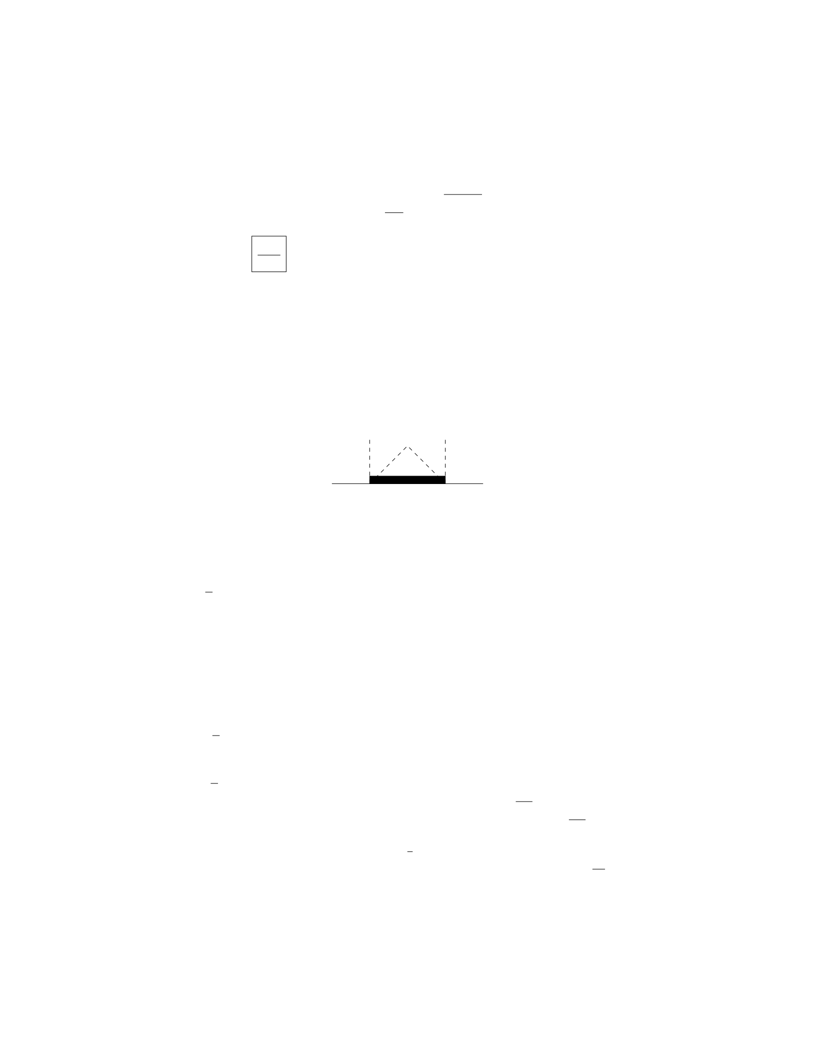
Step 6: Substituting the expression for Wfrom Step 3 and Afrom Step 1
into the equation for ϵin Step 5, we find ϵ=ρπR2Lg
Y πR2.
Step 7: Simplifying, we get ϵ=ρgL
Y.
Therefore, the elongation of the rod when a weight Wis attached to the
lower end is ρgL
Y.
Question 7
Question
A uniform beam of length Land mass Mis supported by a cable as shown in
the figure. The beam makes an angle θwith the horizontal. If the tension in
the cable is T, find the position of the beam’s center of mass (distance from the
left end) in terms of Land θ.
θ
0
Mg
L
T
Solution
Step 1: Let’s find the distance xfrom the left end of the beam to its center of
mass. The weight of the beam acts at its center of mass, which is located at
x=L
2.
Step 2: Next, let’s consider the forces acting on the beam in the y-direction.
The vertical component of tension Tis Tsin(θ), acting upwards. The weight
of the beam is Mg, acting downwards. The net force in the y-direction is zero
since the beam is in equilibrium.
Step 3: Writing the force balance equation in the y-direction: Tsin(θ) = M g
Step 4: Now, let’s consider the torques acting on the beam about the left
end. The torque due to the tension about the left end is T·Lsin(θ), acting
clockwise. The torque due to the weight of the beam about the left end is
Mg ·L
2sin(θ), acting counterclockwise. The net torque about the left end is
zero since the beam is in equilibrium.
Step 5: Writing the torque balance equation about the left end: T·Lsin(θ) =
Mg ·L
2sin(θ)
Step 6: Simplifying the torque balance equation: T=M g
2
Step 7: Substituting the tension into the force balance equation: Mg
2sin(θ) =
Mg
Step 8: Solving for sin(θ): sin(θ) = 2
3
Step 9: Therefore, the position of the beam’s center of mass is x=2L
3.
6

Question 8
Question
A uniform thin rod of length Land mass Mis hinged at one end and suspended
vertically. A horizontal force Fis applied at the other end of the rod, keeping
it in equilibrium. Determine the minimum magnitude of the force Fneeded to
make the rod move from its equilibrium position.
Solution
1. Draw a free-body diagram of the rod. The forces acting on the rod are: -
Weight (mg) acting downward at the center of mass of the rod. - Tension (T)
acting upward at the hinge. - Applied force (F) acting to the right at the end
of the rod.
2. Since the system is in equilibrium, the sum of the torques about any point
must equal zero. Let’s choose the hinge point as the pivot.
3. The torque due to the weight and the tension is zero about the pivot
point because they pass through the pivot. Therefore, only the torque due to
the applied force Fis nonzero:
τ=F·L
4. The torque must balance to keep the system in equilibrium, so:
τ=F·L= 0
5. Thus, the minimum force Fneeded to make the rod move from its
equilibrium position is F= 0 . This means that the rod will not move from its
equilibrium position unless a force greater than zero is applied.
Question 9
Question
A mass of 2 kg is suspended from a vertical spring with a spring constant of 500
N/m. The mass is then displaced downward by 5 cm from its equilibrium posi-
tion and released. Determine the amplitude, angular frequency, and maximum
speed of the mass during its motion.
Solution
Step 1: Determine the amplitude (A) of the oscillation.
A= maximum displacement from equilibrium position
= displacement when the mass is at its maximum distance from equilibrium.
7

Given that the mass is displaced downward by 5 cm, A= 5 cm = 0.05 m.
Step 2: Determine the angular frequency (ω) of the oscillation.
ω=rk
m
=s500 N/m
2 kg
=√250 s−1
= 5√10 s−1.
Step 3: Determine the maximum speed of the mass.
Maximum speed = Aω
= 0.05 m ×5√10 s−1
= 0.25√10 m/s.
Therefore, the amplitude of the motion is 0.05 m, the angular frequency is
5√10 s−1, and the maximum speed of the mass is 0.25√10 m/s.
Question 10
Question
A block of mass mis suspended by a thin wire attached to the ceiling of an
elevator. The elevator moves upward with an acceleration a. Find the tension in
the wire when the elevator moves with constant speed vand when it accelerates
upward with a.
Solution
To solve this problem, we will consider the forces acting on the block in both
situations - when the elevator moves with constant speed and when it accelerates
upward.
Case 1: Constant Speed v
Step 1: Draw the free-body diagram for the block.
Since the elevator is moving with a constant speed v, the net force on the
block is zero.
Step 2: Write the equation of motion in the vertical direction.
The forces acting on the block are the tension in the wire (T) and the
gravitational force (mg), where gis the acceleration due to gravity. The
equation of motion in the vertical direction is:
T−mg = 0
8
Step 3: Solve for the tension T.
From the equation of motion, we have T=mg.
Case 2: Acceleration Upward a
Step 1: Draw the free-body diagram for the block.
Since the elevator is accelerating upward with a, the net force on the block
is in the upward direction.
Step 2: Write the equation of motion in the vertical direction.
The forces acting on the block are the tension in the wire (T) and the
gravitational force (mg). The equation of motion in the vertical direction
is:
T−mg =ma
Step 3: Solve for the tension T.
From the equation of motion, we have T=m(g+a).
Question 11
Question
A uniform cylindrical pillar is standing upright on a rough horizontal surface.
The radius of the pillar is 0.5 m, and its height is 2 m. If the coefficient of
static friction between the pillar and the surface is 0.6, determine the maximum
horizontal force that can be applied at the top of the pillar without causing it
to tip over. The density of the pillar is 500 kg/m3.
Solution
Step 1: To determine the maximum force that can be applied at the top of the
pillar without causing it to tip over, we need to find the limit where the friction
force just balances the tendency for the cylinder to tip.
Step 2: The equilibrium condition for the pillar not to tip over is when the
net torque is zero. The friction force provides the necessary torque to prevent
the tipping.
Step 3: The friction force (Ffriction) at the base of the pillar must balance
the external force applied at the top (F) to prevent tipping. The maximum
static friction force is fmax =µs·N, where µsis the coefficient of static friction
and Nis the normal force.
Step 4: The normal force Nacting on the pillar is equal to the weight of
the pillar mg where mis the mass of the pillar and gis the acceleration due to
gravity.
Step 5: The mass of the cylinder can be calculated using its density ρand
volume V. The volume of the cylinder is given by V=πr2h.
9

Step 6: Substituting the expressions for the mass and weight of the pillar
into the expression for the maximum friction force, we have fmax =µsρπr2hg.
Step 7: The torque about the bottom of the pillar due to the applied force
is T=F r. To keep the pillar from tipping, this torque must be balanced by the
torque due to the friction force acting at the base of the pillar, T=fmax(h/2).
Step 8: Substituting the expressions for torque and the maximum friction
force, we have F r =µsρπr2hg ·(h/2).
Step 9: Solving for the maximum force F, we find F=µsρπr2hgh
2r.
Step 10: Now, substituting the given values (µs= 0.6, r= 0.5 m, h= 2 m,
ρ= 500 kg/m3,g= 9.81 m/s2) into the equation, we can find the maximum
horizontal force that can be applied at the top of the pillar without causing it
to tip over.
Step 11: Calculating F, we get:
F=(0.6)(500)(π)(0.52)(2)(9.81)(2)
2(0.5)
F=150π
2×9.81
F= 738.024 N
Therefore, the maximum horizontal force that can be applied at the top of
the pillar without causing it to tip over is 738.024 N.
Question 12
Question
A steel cable of length 10.0 m and diameter 2.0 cm hangs vertically from a
ceiling. If the Young’s modulus of the steel is 2.00 ×10¹¹ N/m2, what is the
elongation of the cable due to its own weight? Assume the density of steel is
7.8 g/cm3.
Solution
Step 1: We need to find the weight of the cable first. The volume of the steel
cable can be calculated using the formula for the volume of a cylinder:
V=πd
22
·L
where dis the diameter and Lis the length of the cable.
Given that the diameter d= 2.0 cm and the length L= 10.0 m, we have:
V=π2.0 cm
22
·10.0 m
10

V=π(1.0 cm2)·10.0 m = 10πcm2·m
Since the density of steel is 7.8 g/cm3, the mass of the cable can be calculated
as:
m= density ×V= 7.8 g/cm3×10πcm2·m
Converting grams to kilograms, we have:
m= 7.8×10³kg/m3×10πm = 78πkg
The weight of the cable can be calculated by multiplying the mass by the
acceleration due to gravity, g= 9.81 m/s2:
Fweight =m·g= 78πkg ×9.81 m/s2
Fweight = 766.86πN
Step 2: The tension in the cable at equilibrium must balance the weight of
the cable. The strain (ϵ) in the cable can be calculated using Hooke’s law:
ϵ=Fweight ·L
A·Y
where Ais the cross-sectional area of the cable and Yis the Young’s modulus.
The cross-sectional area of the cable can be calculated using the formula for
the area of a circle:
A=πd
22
A=π(1.0 cm)2=πcm2
Now, substitute the values into the equation for strain:
ϵ=766.86π·10.0
π·2.00 ×1011
ϵ=7668.6
2.00 ×10¹¹
ϵ≈3.834 ×10⁻⁵
Step 3: The elongation (∆L) due to the cable’s weight can be calculated
using the formula:
∆L=ϵ·L
∆L= 3.834 ×10−5×10.0 m
∆L= 3.834 ×10⁻⁴m
Therefore, the elongation of the cable due to its own weight is approximately
3.834 ×10⁻⁴meters.
11

Question 13
Question
A thin uniform rod of length Land mass Mis hinged at one end. A block of
mass mis suspended from the other end of the rod. The system is in equilibrium
with the rod at an angle θabove the horizontal. Find the tension in the rod
and the normal force at the hinge.
Solution
Step 1: Draw a free-body diagram for the block and rod system. Step 2: Write
out the force balance equations for the block and rod system. Step 3: Solve for
the tension in the rod and the normal force at the hinge.
Question 14
Question
A uniform beam of length Land mass Mis supported by a pivot a distance x
from one end. A weight Whangs at the other end of the beam. The beam is
in equilibrium at an angle θwith the horizontal. What is the magnitude of the
force at the pivot in terms of M,L,x,W, and θ?
Solution
Step 1: Draw a free-body diagram of the beam. The forces acting on the beam
are: - The weight of the beam acting at its center of mass L/2. - The force at
the pivot point. - The weight Wacting at the end of the beam.
Step 2: Write down the torque equation. Since the beam is in equilibrium,
the net torque about any point must be zero. Choose the pivot point as the
point about which to calculate the torques.
The torque due to the weight of the beam is −Mg
2Lsin θ(negative because
it’s trying to rotate the beam counter-clockwise). The torque due to the weight
Wis W(x+L/2) sin θ. The torque due to the pivot force is Fp(x) cos θ.
Setting the sum of torques equal to zero, we have:
−MgL
2sin θ+W(x+L
2) sin θ−Fp(x) cos θ= 0
Step 3: Solve for the force at the pivot point.
Fp(x) = MgL
2sin θ+W(x+L
2) sin θ
Therefore, the magnitude of the force at the pivot is MgL
2sin θ+W(x+
L
2) sin θ.
12

Question 15
Question
A uniform plank of length Land mass Mis supported by a horizontal force Fat
one end and a vertical wall at the other end. The plank makes an angle θwith
the horizontal. If the coefficient of static friction between the plank and the
wall is µs, determine the range of values for Fthat allow the plank to remain
in equilibrium.
Solution
Step 1: We start by drawing a free-body diagram of the plank. There are three
forces acting on the plank: the force of gravity (Mg) acting at the center of
mass, the normal force (N) exerted by the wall, and the horizontal force (F)
applied at one end. Step 2: Break down the forces acting on the plank into their
components. The normal force Nhas both horizontal and vertical components.
The vertical component must balance the gravitational force (Mg), and the
horizontal component must balance the frictional force (ffriction =µsN). Step
3: Write the equilibrium conditions for the plank. In the vertical direction:
Ncos θ=Mg
And in the horizontal direction:
F=Nsin θ+µsN
Step 4: Substitute the expression for Nfrom the vertical equilibrium condition
into the horizontal equilibrium condition:
F=Mg sin θ
cos θ−µssin θ
Step 5: To determine the range of values for Fthat allow the plank to remain
in equilibrium, we set up the inequality based on the static friction condition
(ffriction ≤µsN):
µsN≤µsMg
µsMg
cos θ≤µsMg
F≥Mg tan θ
So the range of values for Fthat allow the plank to remain in equilibrium is
F≥Mg tan θ.
13
Question 16
Question
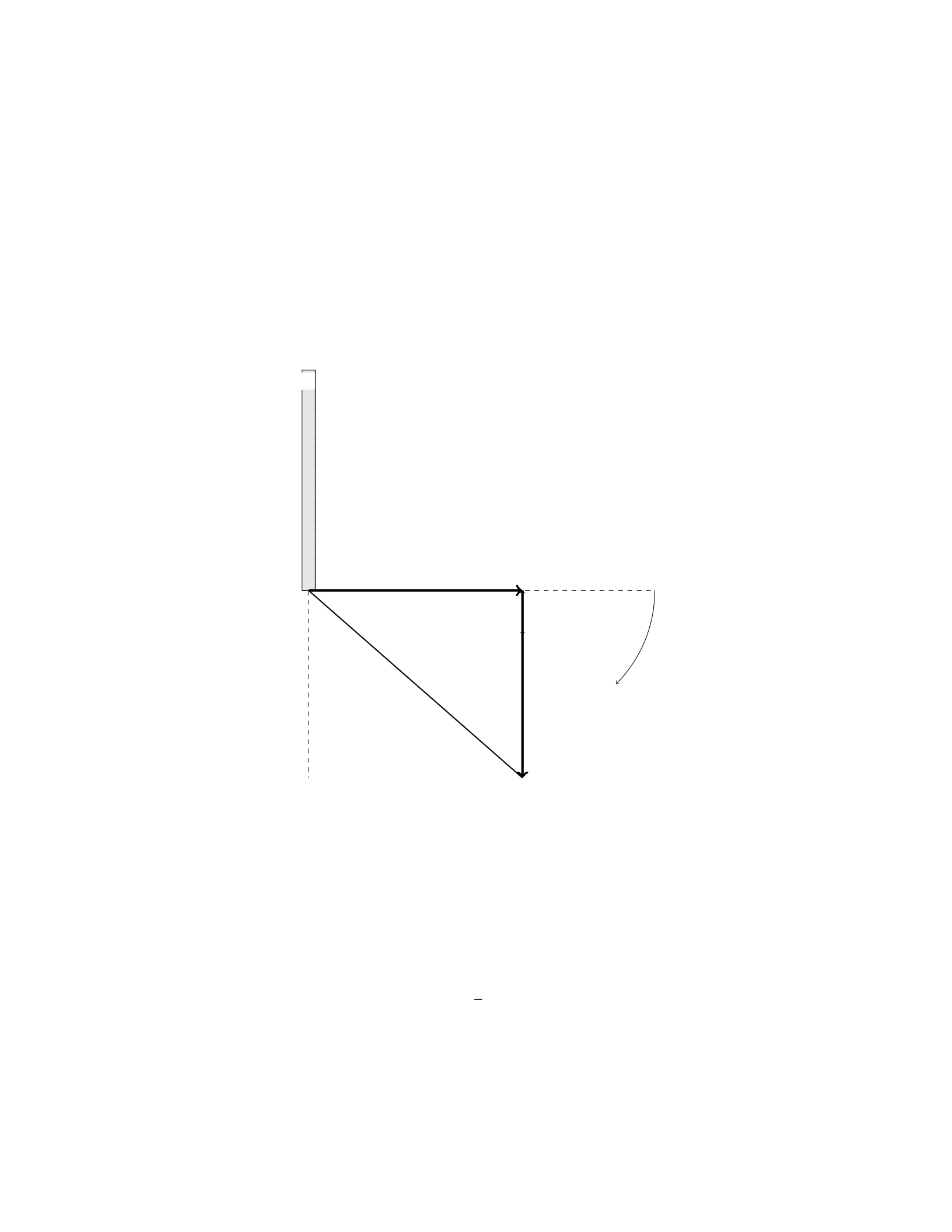
A uniform rod of length Land mass Mis pivoted about one end and is held in
a horizontal position by a string attached a distance xfrom the pivot point, as
shown in the figure below. The string breaks and the rod swings down until it
comes to rest in a vertical position. Determine the angular speed of the rod as
it swings into a vertical position.
x
θ
L
L−x
r
r′
Solution
Let’s start by analyzing the forces acting on the rod in the horizontal position
before the string breaks. The forces acting on the rod are the tension in the
string (T) and the force of gravity acting at the center of mass of the rod.
Step 1: Set up the torque equation in the horizontal position In
the horizontal position, the torque due to the tension at the pivot point must
balance the torque due to the gravitational force about the pivot point. The
torque equations can be written as:
T·x=1
2Mg ·L
where gis the acceleration due to gravity.
14

Step 2: Determine the tension in the string before it breaks From
the torque equation, we can solve for the tension Tas:
T=Mg ·L
2x
Step 3: Set up the conservation of energy equation When the string
breaks, the rod no longer has any external forces acting on it, and so we can
use the conservation of energy to determine the angular speed of the rod in the
vertical position. The initial total mechanical energy is equal to the final total
mechanical energy:
1
2Iω2=Mgh
where I=1
3ML2is the moment of inertia of the rod about the pivot point,
ωis the angular speed of the rod, and h=Lis the height the center of mass
falls.
Step 4: Solve for the angular speed Substitute the moment of inertia
Iand the height hinto the conservation of energy equation. Solving for ω, we
get:
ω=r3g
2L
Therefore, the angular speed of the rod as it swings into a vertical position
is q3g
2L.
Question 17
Question
A uniform bar of length Land mass Mis supported by a scale at a distance a
from one end. A weight of mass mis hung at a distance bfrom the same end
where the support is located. If the scale reads F, what is the distance ain
terms of m,M,L,b, and Ffor the bar to be in equilibrium?
Solution
Step 1: Draw a free body diagram of the bar. We can consider three forces
acting on the bar: the gravitational force Mg acting at the center of mass,
the normal force Ffrom the scale acting at a distance afrom one end, and
the weight mg acting at a distance bfrom the same end. Step 2: Set up the
equilibrium condition for forces in the vertical direction. The sum of the forces
in the vertical direction must be zero for the bar to be in equilibrium. Therefore,
we have:
F−Mg −mg = 0
15

Step 3: Calculate the torque about the point where the scale is located. The
torque about the point where the scale is located must also be zero for the bar
to be in equilibrium. The torque due to the normal force Fand the weight mg
are:
τF=F·0=0
τmg =mg(L−b)
The torque due to the gravitational force Mg can be calculated as:
τMg =M a
Step 4: Set up the torque equilibrium condition. The sum of the torques must
be zero for the bar to be in equilibrium. Therefore, we have:
τMg +τmg = 0
Ma +mg(L−b)=0
Step 5: Solve for the distance a. Solving for ain the torque equilibrium equation
gives:
a=−mg(L−b)
M
Thus, the distance ain terms of m,M,L,b, and Ffor the bar to be in
equilibrium is a=−mg(L−b)
M.
Question 18
Question
A 2 kg mass is suspended from the ceiling by two identical strings, each making
an angle of 30 degrees with the ceiling. Find the tension in each string.
Solution
Step 1: Draw a free body diagram of the mass showing the forces acting on it.
Step 2: Resolve the weight of the mass into its vertical and horizontal com-
ponents.
Step 3: Apply the equilibrium condition in the vertical direction to set up an
equation involving the tension forces and the vertical component of the weight.
Step 4: Apply the equilibrium condition in the horizontal direction to set up
an equation involving the tension forces and the horizontal component of the
weight.
Step 5: Solve the two equations simultaneously to find the tensions in the
strings.
16

Question 19
Question
A uniform horizontal beam of length Land mass Mis supported by a vertical
cable attached at the beam’s midpoint. If a block of mass mis attached to the
right end of the beam, what is the tension in the cable when the system is in
equilibrium? Assume the beam has negligible mass compared to the block and
no friction exists between the beam and the block.
Solution
Step 1: Draw a free-body diagram for the block at the right end of the beam.
Label the forces acting on it. Step 2: Write out the equation for equilibrium in
the vertical direction: PFy= 0. Step 3: Write out the equation for rotational
equilibrium about the point where the cable is attached: Pτ= 0.
Question 20
Question
A spring with a spring constant of 200 N/m is compressed by a distance of 0.1
m. A block of mass 2 kg is placed on top of the spring and released. The block
then compresses the spring by an additional 0.05 m before coming to rest. Find
the coefficient of kinetic friction between the block and the surface.
Note: Neglect air resistance and assume the surface is rough enough that
slipping does not occur between the block and the surface.
Solution
Step 1: Find the total compression of the spring when the block comes to rest.
The work done by the block in compressing the spring is equal to the po-
tential energy stored in the spring when it comes to rest. We can write:
1
2kx2=mgh
Where: k= spring constant = 200 N/m x= initial compression = 0.1 m m
= mass of the block = 2 kg g= acceleration due to gravity = 9.81 m/s2h=
additional compression = ?? (what we need to find)
Solving for h:
200 ×0.12= 2 ×9.81 ×h
20 = 19.62h
17

h=20
19.62 ≈1.02 m
So, the total compression of the spring when the block comes to rest is 1.02
m.
Step 2: Calculate the work done by the friction force.
The work done by the friction force is equal to the friction force multiplied
by the distance over which it acts. We know the friction force does negative
work, so the work done by the friction force can be calculated as:
Wfriction =−Ffriction ×d
Where: Ffriction =µkN d = total compression of the spring = 1.02 m N=
normal force = mg
Step 3: Calculate the work done by the friction force.
The work done by the friction force is equal to the decrease in mechanical
energy of the block-spring system. Thus:
Wfriction =−∆U
The change in potential energy of the block-spring system is equal to the
negative of the work done by the spring force. Hence:
Wfriction =−(1
2kx2
1−1
2kx2
2)
Wfriction =−(1
2×200 ×0.12−1
2×200 ×1.022)
Wfriction =−1
2×200 ×(0.12−1.022)
Wfriction =−1
2×200 ×(−0.996) = 99.6 J
Therefore, the work done by the friction force is 99.6 J.
Step 4: Find the coefficient of kinetic friction.
Since the work done by the friction force is equal to the friction force mul-
tiplied by the distance over which it acts, we have
Ffriction ×1.02 = 99.6
µk×mg ×1.02 = 99.6
µk=99.6
2×9.81 ×1.02 ≈0.492
Therefore, the coefficient of kinetic friction between the block and the surface
is approximately 0.492.
18

Question 21
Question
A beam of length Lis supported by a hinge at one end and a cable attached to
the wall at a distance xfrom the hinge. The beam has a mass mand a uniform
density. Find the tension in the cable required to support the beam.
Solution
Step 1: Consider the forces acting on the beam. Since the beam is in equilibrium,
the sum of the forces in the vertical direction must be zero. Let Tbe the tension
in the cable. The gravitational force acting on the beam can be split into two
components: one parallel to the beam (mg sin θ) and one perpendicular to the
beam (mg cos θ).
Step 2: Calculate the perpendicular force components. The perpendicular
component of the gravitational force (mg cos θ) creates a torque about the hinge.
The torque due to this component is −mg cos θ·L. In order for the beam to be
in equilibrium, the torque created by the tension (T·(L−x)) must balance the
torque from the perpendicular component of gravity.
Step 3: Set up the equilibrium condition. Equating the torques, we have:
T·(L−x) = mg cos θ·L
Step 4: Determine the expression for cos θ. Using the geometry of the situ-
ation, we see that cos θ=L−x
L.
Step 5: Substitute the expression for cos θinto the equilibrium equation.
Substitute cos θ=L−x
Linto the equilibrium equation: T·(L−x) = mg ·L−x
L·L
Step 6: Simplify the equation. After simplifying, we have: T·(L−x) =
mg ·(L−x)
Step 7: Solve for the tension in the cable. Dividing both sides by (L−x),
we get: T=mg
Therefore, the tension in the cable required to support the beam is mg.
Question 22
Question
A uniform beam of length Land mass Mis supported by pivot at one end and
a vertical cable at a distance dfrom the pivot. A weight of mass mis placed at
the far end of the beam. Determine the tension in the cable when the system
is in equilibrium.
Solution
Step 1: Draw a free-body diagram of the beam and weight. Let Tbe the tension
in the cable, Rbe the reaction force at the pivot, and Wbe the weight of the
beam. We also have the weight of the mass macting downwards.
19

Step 2: Write down the torque balance equation. For the beam to be in
equilibrium, the sum of the torques acting on the beam about the pivot point
must be zero. Xτ= 0
T d −WL
2+mgL = 0
Step 3: Resolve forces vertically and horizontally. In the vertical direction,
we have:
R+T−W−mg = 0
Step 4: Solve the torque equation. Substitute the expression for Winto the
torque equation and solve for T:
T d −Mg
2L+mgL = 0
T d =Mg
2L−mgL
T=MgL
2d−mg
Therefore, the tension Tin the cable when the system is in equilibrium is
MgL
2d−mg.
Question 23
Question
A uniform 5.0 m long rod of mass 3.0 kg is hinged at one end. A 2.0 kg ball
is attached to the other end. The ball is released from rest at an angle of 60
degrees above the horizontal. Find the force exerted by the hinge on the rod at
the instant the ball is released.
Solution
Step 1: We can break the forces acting on the system into horizontal and vertical
components. Let’s define the positive x-direction as to the right and the positive
y-direction as upwards. The force by the hinge will have both horizontal and
vertical components.
Step 2: For equilibrium in the horizontal direction, the net force must be
zero. The only horizontal force is the tension Tin the rod, and it acts to the
right. Therefore,
Tcos(60◦)=0
Step 3: For equilibrium in the vertical direction, the net force must also be
zero. We have the weight of the ball and the tension in the rod as the vertical
forces. The tension Tacts at an angle of 60 degrees from the vertical.
Tsin(60◦)−mballg= 0
20

Step 4: Now, we can substitute mball = 2.0 kg, mrod = 3.0 kg, g= 9.81
m/s2, and solve for T.
Tsin(60◦)−(2.0)(9.81) = 0
T=2.0(9.81)
sin(60◦)
Step 5: Calculate Tto find the force exerted by the hinge on the rod. Make
sure to convert the angle from degrees to radians before computing the value.
T≈2.0×9.81
sin60 ×π
180
Question 24
Question
A uniform rod of length Land mass Mis pivoted about an end and is held
horizontally, with the other end pressed against a vertical wall. The rod makes
an angle θwith the horizontal. Determine the magnitude of the force exerted
by the wall on the rod.
Solution
1. Draw a free body diagram of the rod, showing all the forces acting on it. The
forces include the weight of the rod acting at its center of mass, the force of the
pivot, and the force exerted by the wall.
2. Resolve all the forces into components parallel and perpendicular to the
rod. Let Fwbe the force exerted by the wall, Nbe the normal force exerted
by the pivot, Mg be the weight of the rod, and Rbe the reaction force at the
pivot.
3. Write down the equations for the forces in the perpendicular direction:
N=Mg cos θ
R=Fwsin θ
4. Write down the equations for the forces in the parallel direction:
Fw=Mg sin θ
5. Combining the equations from step 3 and step 4, we can solve for the
magnitude of the force exerted by the wall on the rod:
Fw=Mg sin θ
21
Question 25
Question
A horizontal bar of length Land mass Mis attached at one end to a wall by
a hinge. The bar is held horizontally at the other end by a cable making an
angle θwith the bar. The tension in the cable is T. Determine the tension in
the cable needed just to lift the bar off the ground.
Solution
Let’s consider the forces acting on the bar in equilibrium. Step 1: Draw the
free-body diagram of the bar.
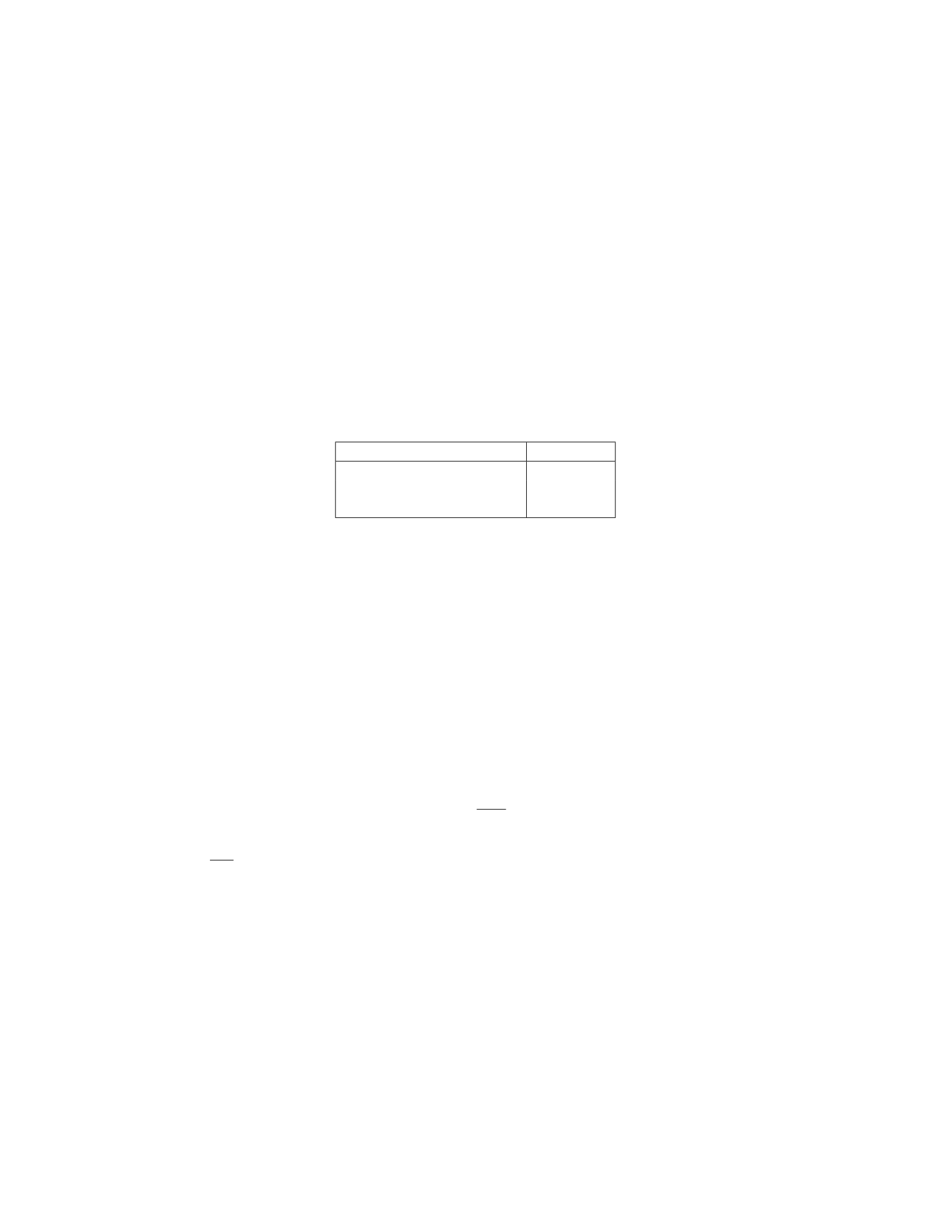
Force Magnitude
Tension from the cable T
Weight of the bar Mg
Normal force at the hinge N
Step 2: Write the force equations in the vertical and horizontal directions. In
the vertical direction, the forces must balance:
N=Mg
In the horizontal direction, the forces must also balance:
Tsin θ=N
Step 3: Compute the tension Tneeded just to lift the bar off the ground.
Substitute N=Mg into Tsin θ=N:
Tsin θ=Mg
Solving for Tgives:
T=Mg
sin θ
Therefore, the tension in the cable needed just to lift the bar off the ground is
Mg
sin θ.
Question 26
Question
A uniform beam of mass Mand length Lis supported by a rope attached a
distance xfrom one end, as shown in the diagram below. The beam has a mass
2Mand length 2L. If the system is in equilibrium, determine the tension in the
rope.
22
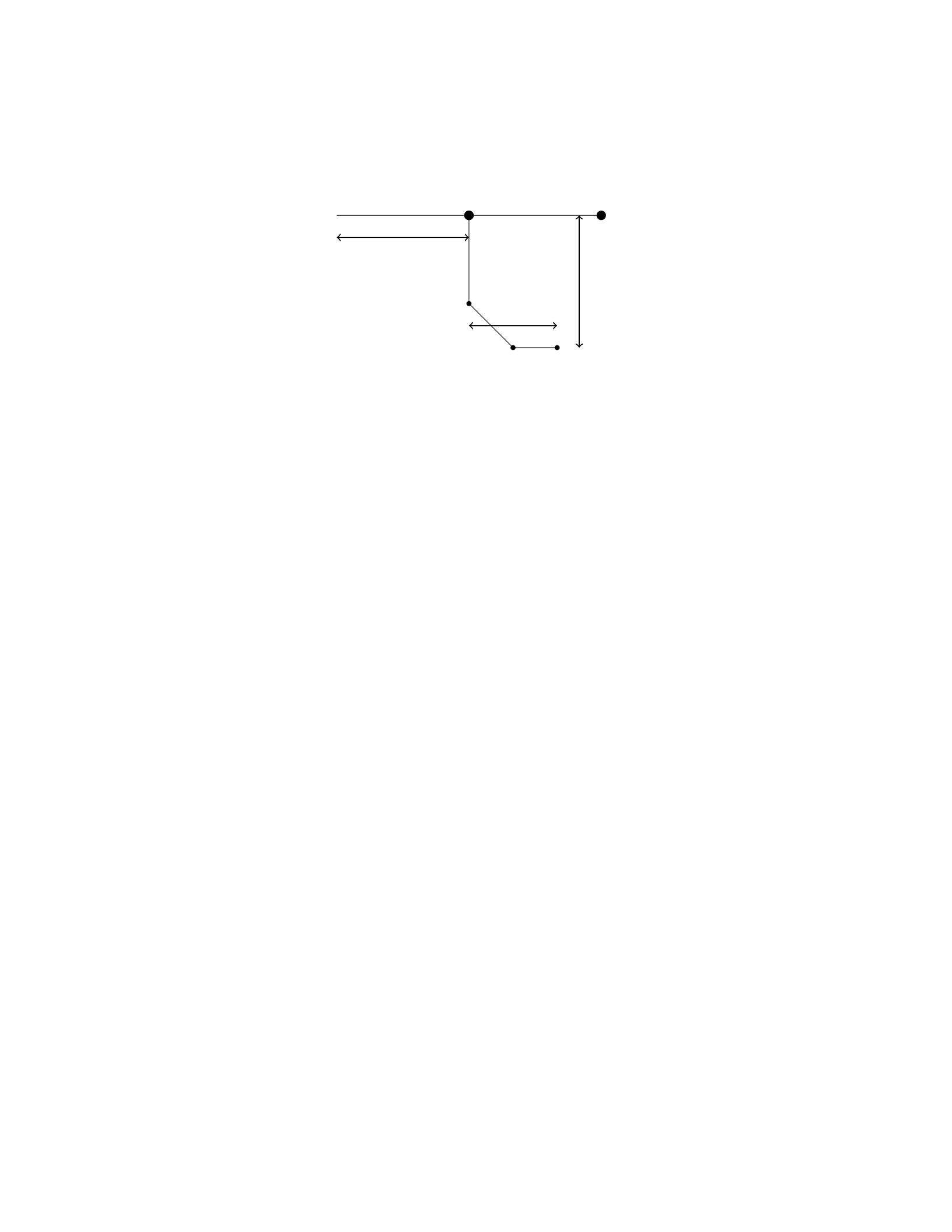
L
2L
x
M2M
Solution
Step 1: We will first draw the free body diagram for the beam. There are three
forces acting on the beam: the weight of the beam (2Mg) acting downward at
the center of the beam, the tension force from the rope (T) acting upward at a
distance xfrom one end, and the reaction force at the support point (N) acting
upward at the pivot.
Step 2: Let’s sum the forces in the vertical direction to find the expression
for the tension T. Taking upward forces as positive, we have:
N−2Mg +T= 0
N= 2Mg −T
Step 3: Next, let’s sum the torques about the pivot point. The torque due
to the force Nis zero since it acts at the pivot. The torque due to the force
2Mg about the pivot is MgL. The torque due to the tension force Tabout the
pivot is T(x+ 2L). The condition for rotational equilibrium gives:
T(x+ 2L) = MgL
Step 4: Now we can solve the two equations we obtained in Step 2 and Step
3 to find the tension T. Substituting N= 2Mg −Tinto T(x+ 2L) = MgL, we
get:
(2Mg −T)(x+ 2L) = MgL
2Mgx + 4MgL −T x −2T L =M gL
T x + 2T L = 2Mgx + 4MgL
T(x+ 2L)=2Mg(x+ 2L)
T= 2Mg
Therefore, the tension in the rope is 2Mg.
23

Question 27
Question
A uniform rod of length Land mass Mis pivoted at one end. A force Fis
applied perpendicular to the rod at a distance dfrom the pivot, as shown in the
figure. Find the magnitude and direction of the force needed to hold the rod in
equilibrium.
Pivot
F
Ld
Solution
Step 1: We will begin by drawing a free-body diagram of the rod. Let’s designate
the forces acting on the rod: the force Fat a distance dfrom the pivot, the
weight Mg acting downwards at the center of mass of the rod, and the normal
force Nacting upwards at the pivot point to keep the rod in equilibrium.
Step 2: We will write the torque equation about the pivot point to find the
force Fin terms of known quantities. The torque due to force Fis:
τF=F·d
The torque due to the weight Mg is:
τMg =M g ·L
2
Since the rod is in equilibrium, the sum of the torques must be zero:
F·d−Mg ·L
2= 0
Step 3: Solve for the force F:
F·d=Mg ·L
2
F=MgL
2d
Therefore, the magnitude of the force needed to hold the rod in equilibrium is
MgL
2d. To find the direction of the force, we observe that it must be perpendicular
to the rod and directed outward from the pivot point.
24

Question 28
Question
A uniform, thin rod of length Land mass Mis initially at rest on a frictionless
horizontal surface. A force Fis then applied to the other end of the rod in a
direction perpendicular to the rod. Find the magnitude of the force needed to
make the rod tip lift off the surface.
Solution
1. Draw a Free Body Diagram (FBD):
Let’s consider the forces acting on the rod when the tip is about to lift off.
These forces are: - The force of gravity acting at the center of mass Cof the
rod (mg downwards) - The normal force Nexerted by the surface on the rod -
The external force Fapplied at the other end of the rod
2. Write the Equations for Equilibrium:
For the rod to be in equilibrium, the net force acting on it must be zero and the
net torque about any point must also be zero. We’ll choose the pivot point to
be at the point where the rod is touching the surface.
The net force equation in the vertical direction is:
N=mg
The net torque equation about the pivot point is:
F·L= (MgL/2)
3. Solve for the External Force F:
Substitute N=mg and solve the torque equation for F:
F·L= (MgL/2)
F=MgL
2L
F=Mg
2
Thus, the magnitude of the force needed to make the rod tip lift off the
surface is F=Mg
2.
Question 29
Question
A uniform rod of mass Mand length Lis pivoted at its midpoint. Two masses,
each with mass m, are attached to the ends of the rod. Find the period of small
oscillations around the equilibrium position.
25

Solution
Step 1: Identify the force equations for small oscillations.
The forces acting on mass mon the right side of the pivot are the tension in
the rod, gravity, and the force due to motion. The forces acting on the left side
are similar, except the force due to motion is opposite in direction. We start by
writing the force equation for the right side mass m:
T−mg +F=m¨x
where Tis the tension, gis the acceleration due to gravity, Fis the force due
to motion, and ¨xis the acceleration of the mass.
Step 2: Write the force equation for the left side mass m.
The force equation for the left side mass mis:
T−mg −F=m¨x
Step 3: Determine expressions for the tension and force due to motion.
At equilibrium, the tension is merely supporting the weight, so T=mg.
The force due to motion, F, is equal to −kx, where xis the position of the mass
relative to the equilibrium position.
Step 4: Substitute the expressions for tension and force into the force equa-
tions.
For the right side mass m:
mg −mg −kx =m¨x
−kx =m¨x
−k
mx= ¨x
Step 5: Determine the angular frequency ωof oscillations.
The above equation is the differential equation of simple harmonic motion
with angular frequency ω=qk
m.
Step 6: Calculate the period Tof oscillations.
The period T=2π
ω= 2πpm
k.
Therefore, the period of small oscillations around the equilibrium position
for the system is 2πpm
k.
Question 30
Question
A uniform rod of length Land mass Mis suspended horizontally by two vertical
wires of equal length L, as shown in the figure below. The distance between the
wires is b. What is the tension in each wire?
[Figure: a rod suspended horizontally by two vertical wires of equal length
with distance bbetween them]
26

Solution
Let’s denote the tension in each wire as T.
Step 1: The free-body diagram of the rod shows that the forces acting on
the rod are the tensions in the two wires and the gravitational force acting at
the center of the rod.
Step 2: In the horizontal direction, the tensions must balance the weight of
the rod:
2T=Mg
Step 3: Solving for T, we have:
T=Mg
2
Step 4: So, the tension in each wire is Mg
2.
Question 31
Question
A uniform meter stick of mass 0.2 kg is standing vertically with its lower end
resting on a frictionless horizontal surface. A string is attached to the upper
end and pulled horizontally with a force of 12 N. The coefficient of static friction
between the stick and the surface is 0.6. Determine the tension in the string.
Solution
Step 1: First, let’s analyze the forces acting on the meter stick. There are
three forces to consider: the tension in the string (T) pulling to the right, the
weight of the stick acting downward, and the normal force exerted by the ground
perpendicular to the stick.
Step 2: The weight of the stick can be calculated using the formula Fweight =
mg, where mis the mass and gis the acceleration due to gravity. Given that
m= 0.2 kg and g= 9.8 m/s2, we have Fweight = (0.2 kg)(9.8 m/s2).
Step 3: The normal force is equal in magnitude and opposite in direction to
the weight of the stick when the stick is in equilibrium. Therefore, the normal
force is also Fweight.
Step 4: Since the stick is on the verge of sliding horizontally, the maximum
static friction force is µsN, where µsis the coefficient of static friction (0.6) and
Nis the normal force. In this case, the static friction force is acting to the left.
Step 5: For the stick to remain in equilibrium, the net force in the horizontal
direction must be zero. This means that the tension in the string must be equal
in magnitude to the friction force. So we have T=µsN.
Step 6: Substituting N=Fweight and µs= 0.6 into the equation T=µsN,
we get T= 0.6·[0.2 kg ·(9.8 m/s2)].
Step 7: Calculating this expression gives us the tension in the string:
27
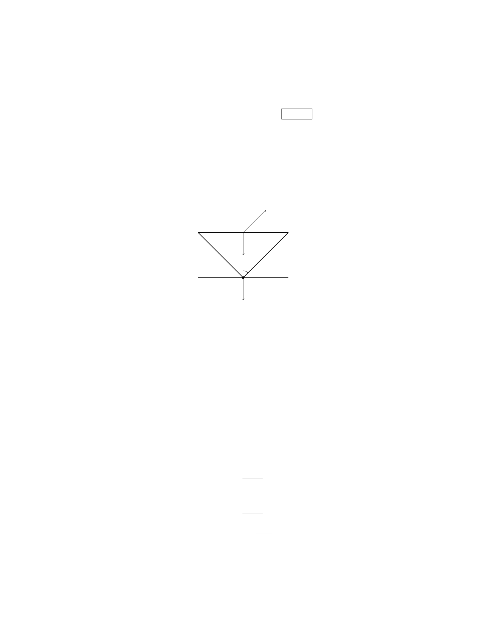
T= 0.6·[0.2 kg ·(9.8 m/s2)] = 1.176 N
Question 32
Question
A uniform rod of length Land mass Mis supported horizontally by two vertical
strings, as shown in the diagram below. The rod makes an angle θwith the
horizontal. Determine the tension in each string in terms of L,M, and θ.
Mg
θ
T1
T2
Solution
Step 1: Setup the following equations: - Sum of forces in the x-direction:
T2cos θ−T1cos θ= 0 - Sum of forces in the y-direction: T1sin θ+T2sin θ−Mg =
0
Step 2: Solve equation (1) for T2in terms of T1:
T2=T1
Step 3: Substitute the expression for T2from Step 2 into equation (2):
T1sin θ+T1sin θ−Mg = 0
Step 4: Simplify equation from Step 3:
2T1sin θ=Mg
Step 5: Solve for T1:
T1=Mg
2 sin θ
Step 6: The tension in each string is equal, so T2=T1:
T2=Mg
2 sin θ
Therefore, the tension in each string is M g
2 sin θ.
28

Question 33
Question
A uniform horizontal beam of length Land mass Mis supported at one end by
a pivot and has a weight (W=Mg) hanging from the other end. A block of
mass mis placed a distance dfrom the pivot as shown in the figure below. If
the block is at rest, find the force exerted by the pivot on the beam.
beam_pivot.png
Solution
Step 1: First, let’s draw a free-body diagram for the beam, showing all the
forces acting on it. The forces acting on the beam are its weight acting at the
center of mass, the normal force exerted by the pivot, and the force exerted by
the block.
Step 2: Since the beam is at rest, the sum of torques about any point must
be zero. For simplicity, we will take torques about the pivot point.
The torque due to the weight of the beam is zero since it acts at the pivot
point.
Step 3: The torque due to the block mabout the pivot is m·g·d(clockwise).
The torque due to the normal force exerted by the pivot is zero since it acts
at the pivot point.
Step 4: Therefore, the sum of torques is equal to zero:
m·g·d= 0
Step 5: Solving for the normal force Nexerted by the pivot on the beam:
N=m·g·d
L
Hence, the force exerted by the pivot on the beam is m·g·d
L.
Question 34
Question
A steel beam of length 5.0 m is supported by a hinge at one end and a vertical
cable attached to the other end. The beam has a mass of 500 kg. If the beam
makes an angle of 30 degrees with the horizontal, what is the tension in the
cable? (Assume g = 9.81 m/s2)
29

Solution
Step 1: First, let’s draw a diagram of the situation to visualize the forces acting
on the beam. We have the weight of the beam acting downward at the center,
the tension in the cable pulling upward at an angle of 30 degrees with the
vertical, and a normal force acting horizontally at the hinge.
Step 2: We can start by calculating the weight of the beam using the formula:
Fgravity =m·g, where mis the mass of the beam and gis the acceleration due
to gravity. Fgravity = (500 kg) ·(9.81 m/s2) = 4905 N
Step 3: Next, we can resolve the force due to gravity into its horizontal and
vertical components. The vertical component will counteract the tension in the
cable. The vertical component of the weight is Fgravity ·sin(30◦). Fvertical =
4905 N ·sin(30◦) = 2452.5 N
Step 4: Since the beam is in equilibrium, the vertical component of the
weight must be balanced by the tension in the cable. Therefore, the tension
in the cable is equal to the vertical component of the weight. T=Fvertical =
2452.5 N
Step 5: Therefore, the tension in the cable is 2452.5 N when the beam makes
an angle of 30 degrees with the horizontal.
Question 35
Question
A uniform meterstick of mass 0.20 kg is supported horizontally by two vertical
strings, one at the 0.10 m mark and the other at the 0.80 m mark. A mass of
0.40 kg is hung from the 0.50 m mark. Calculate the tension in each string.
Solution
Step 1: Draw free body diagrams for the meterstick and the hanging mass. For
the meterstick, we have two tensions acting vertically upwards at the 0.10 m
and 0.80 m marks, and the weight of the meterstick acting downwards at its
center of mass. For the hanging mass, we have the tension in the string acting
upwards and the weight of the mass acting downwards.
Step 2: Write out the equations of equilibrium for each object. For the
meterstick: XFy=T1+T2−mg = 0
T1+T2=mg
For the hanging mass:
XFy=T2−mg′= 0
T2=mg′
where mis the mass of the meterstick, gis the acceleration due to gravity, and
g′is the mass of the hanging mass times the acceleration due to gravity.
30

Step 3: Calculate the stress in the rod. The stress in the rod, σ, is given
by:
σ=F
A=ρ·πd2
4·L·g
πd2
4
=ρ·g·L
Step 4: Calculate the strain in the rod. The strain in the rod, ϵ, is given
by:
ϵ=σ
Y
Step 5: Calculate the elongation of the rod. The elongation of the rod, ∆L,
is given by:
∆L=ϵ·L=ρ·g·L2
Y
Therefore, the elongation of the rod under its own weight is ρ·g·L2
Y.
Question 2
Question
A solid cylinder of radius Rand mass Mis resting on a rough inclined plane
with angle θ. The coefficient of kinetic friction between the cylinder and the
incline is µk. If the cylinder starts to slide down the incline, determine the
acceleration of the cylinder.
Solution
Step 1: Draw a free-body diagram for the cylinder. The forces acting on the
cylinder include the gravitational force (mg) acting downwards, the normal force
(N) acting perpendicular to the incline, the frictional force (fk) acting opposite
to the direction of motion, and the component of the gravitational force parallel
to the incline. Step 2: Break down the gravitational force into components
parallel and perpendicular to the incline. The component of the gravitational
force parallel to the incline is mg sin(θ), and the component perpendicular to the
incline is mg cos(θ). Step 3: Write down the net force equation in the direction
parallel to the incline. The net force in the direction parallel to the incline
is equal to the component of the gravitational force minus the force of kinetic
friction. Therefore, we have:
Ma =mg sin(θ)−fk
Step 4: Express the force of kinetic friction based on the coefficient of kinetic
friction. The force of kinetic friction can be expressed as fk=µkN. And
the normal force, N, can be found by balancing forces in the perpendicular
direction:
N=mg cos(θ)
2

Step 5: Substitute the expression for the force of kinetic friction and the normal
force into the net force equation. Substitute fk=µkNand N=mg cos(θ) into
the net force equation:
Ma =mg sin(θ)−µkmg cos(θ)
Step 6: Solve for acceleration, a. Solving for a, we get:
a=g(sin(θ)−µkcos(θ))
Therefore, the acceleration of the cylinder sliding down the incline is a=
g(sin(θ)−µkcos(θ)).
Question 3
Question
A uniform cylindrical beam of radius Rand length Lis hinged at one end and
propped up by a support at an angle θas shown in the figure below. The beam
has a mass Mand is in static equilibrium. Determine the force exerted by the
support on the beam and the force exerted by the hinge.
mg
NF
θ
M
Solution
Step 1: Draw free body diagrams of the beam and show all forces acting on it.
Step 2: Write down the equilibrium conditions for the forces acting in the
perpendicular and parallel directions.
Step 3: Solve the equilibrium equations to find the unknown forces.
Question 4
Question
A uniform beam of length Land mass Mis suspended horizontally by two ropes
attached at each end of the beam. The beam is supported by a vertical force F
applied at its midpoint. If the tension in each rope is given by T, determine the
3

magnitude and direction of the supporting force Fneeded to keep the beam in
equilibrium.
Solution
Step 1: Draw a free body diagram of the beam. The forces acting on the beam
are the tension forces Tin the ropes, the vertical force Fat the midpoint, the
gravitational force Mg acting at the center of mass, and the reaction forces R
at the endpoints holding up the beam.
Step 2: Write down the sum of forces in the vertical direction equals to 0
since the beam is in equilibrium:
R+R−Mg −F= 0
Solving for Fgives:
F= 2R−Mg
Step 3: Write down the sum of torques about the midpoint equals to 0 since
the beam is in rotational equilibrium. Torque due to M g and Fwill cause
clockwise rotation while torque due to Twill cause counterclockwise rotation.
The torques can be expressed as:
0 = L
2T−L
2T−L
4F
Solving for Fgives:
F= 2T
Step 4: Substitute F= 2Tinto the equation obtained in Step 2 to get:
2T= 2R−Mg =⇒R=T+Mg
2
So the required supporting force Fneeded to keep the beam in equilibrium
is 2Tin the direction required to counteract the gravitational force.
Question 5
Question
A cylindrical steel column supports a load of 5000 N. The column has a diameter
of 10 cm and a height of 3 m. If the Young’s modulus for steel is 2 ×10¹¹ N/m2,
determine the change in length of the column under the load.
Solution
Step 1: First, we need to find the cross-sectional area of the column in order to
calculate the stress applied to it. The cross-sectional area of a cylinder is given
by the formula:
A=πr2
4

where ris the radius of the cylinder. Given the diameter of the column is 10
cm, the radius ris half of the diameter, so r= 5 cm = 0 .05 m.
Therefore, the cross-sectional area is:
A=π(0.05)2
Step 2: Now, we can calculate the stress (σ) applied to the column using the
formula:
σ=F
A
where Fis the load applied. Given F= 5000 N, we can substitute the values
of Fand Ainto the formula to find σ.
Step 3: With the stress found, we can calculate the strain (ε) using Hooke’s
Law:
σ=E·ε
where Eis the Young’s modulus. Given E= 2 ×10¹¹ N/m2, we can substitute
the values of σand Einto the formula to find ε.
Step 4: To find the change in length of the column (∆L), we use the formula:
∆L=ε·L
where Lis the original length of the column. Given L= 3 m, we can substitute
the values of εand Linto the formula to find ∆L.
Question 6
Question
A uniform cylindrical steel rod of length Land radius Ris hanging vertically
from its upper end. If the Young’s modulus of steel is Y, find the elongation of
the rod when a weight Wis attached to the lower end. Assume that the density
of steel is ρ.
Solution
Step 1: First, let’s determine the cross-sectional area of the rod. The cross-
sectional area of a cylinder is given by A=πR2.
Step 2: Next, we need to find the mass mof the rod. The volume of a cylinder
is V=πR2L, and the density is ρ=m
V. Solving for m, we get m=ρπR2L.
Step 3: The weight Wis given by W=mg, where gis the acceleration due to
gravity. Substituting the expression for mfrom Step 2, we have W=ρπR2Lg.
Step 4: The stress σin the rod due to the weight is given by σ=F
A, where
Fis the force due to the weight. Since F=W, we get σ=W
A.
Step 5: The strain ϵin the rod is related to the stress by Hooke’s Law:
σ=Y ϵ, where Yis the Young’s modulus. So, ϵ=W
Y A .
5
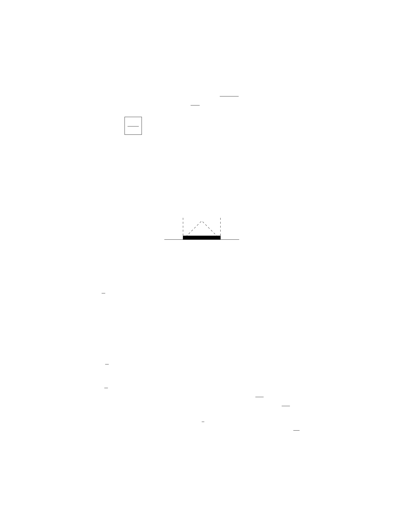
Step 6: Substituting the expression for Wfrom Step 3 and Afrom Step 1
into the equation for ϵin Step 5, we find ϵ=ρπR2Lg
Y πR2.
Step 7: Simplifying, we get ϵ=ρgL
Y.
Therefore, the elongation of the rod when a weight Wis attached to the
lower end is ρgL
Y.
Question 7
Question
A uniform beam of length Land mass Mis supported by a cable as shown in
the figure. The beam makes an angle θwith the horizontal. If the tension in
the cable is T, find the position of the beam’s center of mass (distance from the
left end) in terms of Land θ.
θ
0
Mg
L
T
Solution
Step 1: Let’s find the distance xfrom the left end of the beam to its center of
mass. The weight of the beam acts at its center of mass, which is located at
x=L
2.
Step 2: Next, let’s consider the forces acting on the beam in the y-direction.
The vertical component of tension Tis Tsin(θ), acting upwards. The weight
of the beam is Mg, acting downwards. The net force in the y-direction is zero
since the beam is in equilibrium.
Step 3: Writing the force balance equation in the y-direction: Tsin(θ) = M g
Step 4: Now, let’s consider the torques acting on the beam about the left
end. The torque due to the tension about the left end is T·Lsin(θ), acting
clockwise. The torque due to the weight of the beam about the left end is
Mg ·L
2sin(θ), acting counterclockwise. The net torque about the left end is
zero since the beam is in equilibrium.
Step 5: Writing the torque balance equation about the left end: T·Lsin(θ) =
Mg ·L
2sin(θ)
Step 6: Simplifying the torque balance equation: T=M g
2
Step 7: Substituting the tension into the force balance equation: Mg
2sin(θ) =
Mg
Step 8: Solving for sin(θ): sin(θ) = 2
3
Step 9: Therefore, the position of the beam’s center of mass is x=2L
3.
6

Question 8
Question
A uniform thin rod of length Land mass Mis hinged at one end and suspended
vertically. A horizontal force Fis applied at the other end of the rod, keeping
it in equilibrium. Determine the minimum magnitude of the force Fneeded to
make the rod move from its equilibrium position.
Solution
1. Draw a free-body diagram of the rod. The forces acting on the rod are: -
Weight (mg) acting downward at the center of mass of the rod. - Tension (T)
acting upward at the hinge. - Applied force (F) acting to the right at the end
of the rod.
2. Since the system is in equilibrium, the sum of the torques about any point
must equal zero. Let’s choose the hinge point as the pivot.
3. The torque due to the weight and the tension is zero about the pivot
point because they pass through the pivot. Therefore, only the torque due to
the applied force Fis nonzero:
τ=F·L
4. The torque must balance to keep the system in equilibrium, so:
τ=F·L= 0
5. Thus, the minimum force Fneeded to make the rod move from its
equilibrium position is F= 0 . This means that the rod will not move from its
equilibrium position unless a force greater than zero is applied.
Question 9
Question
A mass of 2 kg is suspended from a vertical spring with a spring constant of 500
N/m. The mass is then displaced downward by 5 cm from its equilibrium posi-
tion and released. Determine the amplitude, angular frequency, and maximum
speed of the mass during its motion.
Solution
Step 1: Determine the amplitude (A) of the oscillation.
A= maximum displacement from equilibrium position
= displacement when the mass is at its maximum distance from equilibrium.
7

Given that the mass is displaced downward by 5 cm, A= 5 cm = 0.05 m.
Step 2: Determine the angular frequency (ω) of the oscillation.
ω=rk
m
=s500 N/m
2 kg
=√250 s−1
= 5√10 s−1.
Step 3: Determine the maximum speed of the mass.
Maximum speed = Aω
= 0.05 m ×5√10 s−1
= 0.25√10 m/s.
Therefore, the amplitude of the motion is 0.05 m, the angular frequency is
5√10 s−1, and the maximum speed of the mass is 0.25√10 m/s.
Question 10
Question
A block of mass mis suspended by a thin wire attached to the ceiling of an
elevator. The elevator moves upward with an acceleration a. Find the tension in
the wire when the elevator moves with constant speed vand when it accelerates
upward with a.
Solution
To solve this problem, we will consider the forces acting on the block in both
situations - when the elevator moves with constant speed and when it accelerates
upward.
Case 1: Constant Speed v
Step 1: Draw the free-body diagram for the block.
Since the elevator is moving with a constant speed v, the net force on the
block is zero.
Step 2: Write the equation of motion in the vertical direction.
The forces acting on the block are the tension in the wire (T) and the
gravitational force (mg), where gis the acceleration due to gravity. The
equation of motion in the vertical direction is:
T−mg = 0
8
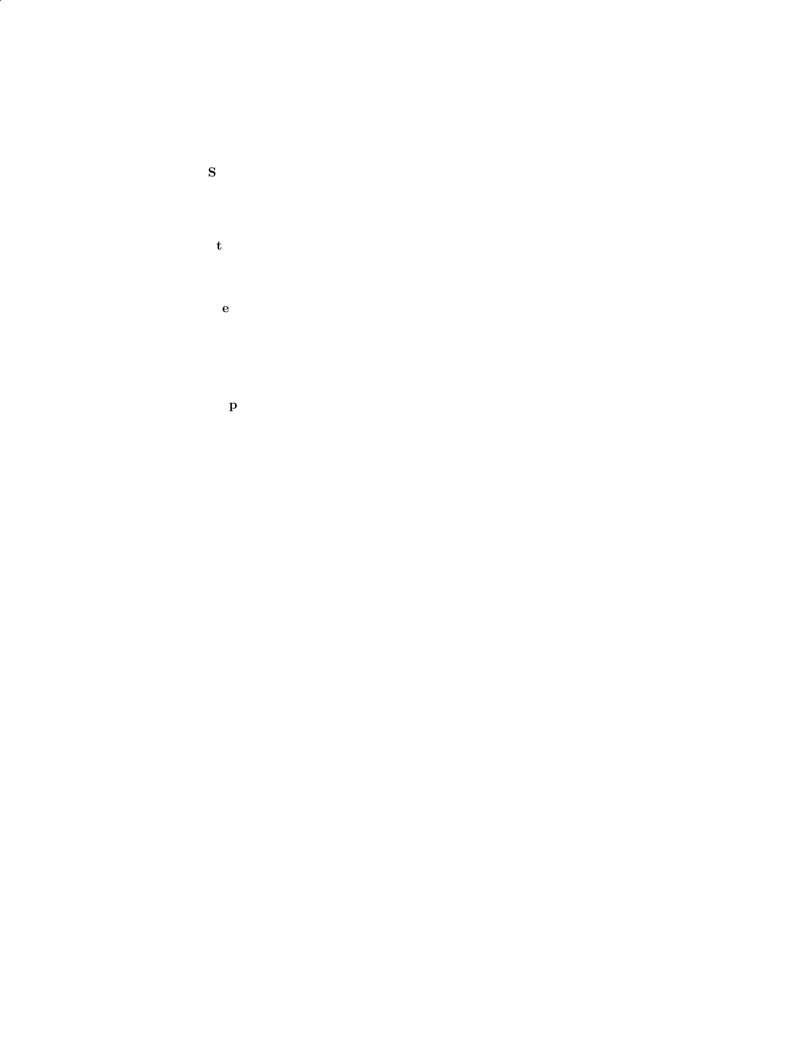
Step 3: Solve for the tension T.
From the equation of motion, we have T=mg.
Case 2: Acceleration Upward a
Step 1: Draw the free-body diagram for the block.
Since the elevator is accelerating upward with a, the net force on the block
is in the upward direction.
Step 2: Write the equation of motion in the vertical direction.
The forces acting on the block are the tension in the wire (T) and the
gravitational force (mg). The equation of motion in the vertical direction
is:
T−mg =ma
Step 3: Solve for the tension T.
From the equation of motion, we have T=m(g+a).
Question 11
Question
A uniform cylindrical pillar is standing upright on a rough horizontal surface.
The radius of the pillar is 0.5 m, and its height is 2 m. If the coefficient of
static friction between the pillar and the surface is 0.6, determine the maximum
horizontal force that can be applied at the top of the pillar without causing it
to tip over. The density of the pillar is 500 kg/m3.
Solution
Step 1: To determine the maximum force that can be applied at the top of the
pillar without causing it to tip over, we need to find the limit where the friction
force just balances the tendency for the cylinder to tip.
Step 2: The equilibrium condition for the pillar not to tip over is when the
net torque is zero. The friction force provides the necessary torque to prevent
the tipping.
Step 3: The friction force (Ffriction) at the base of the pillar must balance
the external force applied at the top (F) to prevent tipping. The maximum
static friction force is fmax =µs·N, where µsis the coefficient of static friction
and Nis the normal force.
Step 4: The normal force Nacting on the pillar is equal to the weight of
the pillar mg where mis the mass of the pillar and gis the acceleration due to
gravity.
Step 5: The mass of the cylinder can be calculated using its density ρand
volume V. The volume of the cylinder is given by V=πr2h.
9

Step 6: Substituting the expressions for the mass and weight of the pillar
into the expression for the maximum friction force, we have fmax =µsρπr2hg.
Step 7: The torque about the bottom of the pillar due to the applied force
is T=F r. To keep the pillar from tipping, this torque must be balanced by the
torque due to the friction force acting at the base of the pillar, T=fmax(h/2).
Step 8: Substituting the expressions for torque and the maximum friction
force, we have F r =µsρπr2hg ·(h/2).
Step 9: Solving for the maximum force F, we find F=µsρπr2hgh
2r.
Step 10: Now, substituting the given values (µs= 0.6, r= 0.5 m, h= 2 m,
ρ= 500 kg/m3,g= 9.81 m/s2) into the equation, we can find the maximum
horizontal force that can be applied at the top of the pillar without causing it
to tip over.
Step 11: Calculating F, we get:
F=(0.6)(500)(π)(0.52)(2)(9.81)(2)
2(0.5)
F=150π
2×9.81
F= 738.024 N
Therefore, the maximum horizontal force that can be applied at the top of
the pillar without causing it to tip over is 738.024 N.
Question 12
Question
A steel cable of length 10.0 m and diameter 2.0 cm hangs vertically from a
ceiling. If the Young’s modulus of the steel is 2.00 ×10¹¹ N/m2, what is the
elongation of the cable due to its own weight? Assume the density of steel is
7.8 g/cm3.
Solution
Step 1: We need to find the weight of the cable first. The volume of the steel
cable can be calculated using the formula for the volume of a cylinder:
V=πd
22
·L
where dis the diameter and Lis the length of the cable.
Given that the diameter d= 2.0 cm and the length L= 10.0 m, we have:
V=π2.0 cm
22
·10.0 m
10

V=π(1.0 cm2)·10.0 m = 10πcm2·m
Since the density of steel is 7.8 g/cm3, the mass of the cable can be calculated
as:
m= density ×V= 7.8 g/cm3×10πcm2·m
Converting grams to kilograms, we have:
m= 7.8×10³kg/m3×10πm = 78πkg
The weight of the cable can be calculated by multiplying the mass by the
acceleration due to gravity, g= 9.81 m/s2:
Fweight =m·g= 78πkg ×9.81 m/s2
Fweight = 766.86πN
Step 2: The tension in the cable at equilibrium must balance the weight of
the cable. The strain (ϵ) in the cable can be calculated using Hooke’s law:
ϵ=Fweight ·L
A·Y
where Ais the cross-sectional area of the cable and Yis the Young’s modulus.
The cross-sectional area of the cable can be calculated using the formula for
the area of a circle:
A=πd
22
A=π(1.0 cm)2=πcm2
Now, substitute the values into the equation for strain:
ϵ=766.86π·10.0
π·2.00 ×1011
ϵ=7668.6
2.00 ×10¹¹
ϵ≈3.834 ×10⁻⁵
Step 3: The elongation (∆L) due to the cable’s weight can be calculated
using the formula:
∆L=ϵ·L
∆L= 3.834 ×10−5×10.0 m
∆L= 3.834 ×10⁻⁴m
Therefore, the elongation of the cable due to its own weight is approximately
3.834 ×10⁻⁴meters.
11

Question 13
Question
A thin uniform rod of length Land mass Mis hinged at one end. A block of
mass mis suspended from the other end of the rod. The system is in equilibrium
with the rod at an angle θabove the horizontal. Find the tension in the rod
and the normal force at the hinge.
Solution
Step 1: Draw a free-body diagram for the block and rod system. Step 2: Write
out the force balance equations for the block and rod system. Step 3: Solve for
the tension in the rod and the normal force at the hinge.
Question 14
Question
A uniform beam of length Land mass Mis supported by a pivot a distance x
from one end. A weight Whangs at the other end of the beam. The beam is
in equilibrium at an angle θwith the horizontal. What is the magnitude of the
force at the pivot in terms of M,L,x,W, and θ?
Solution
Step 1: Draw a free-body diagram of the beam. The forces acting on the beam
are: - The weight of the beam acting at its center of mass L/2. - The force at
the pivot point. - The weight Wacting at the end of the beam.
Step 2: Write down the torque equation. Since the beam is in equilibrium,
the net torque about any point must be zero. Choose the pivot point as the
point about which to calculate the torques.
The torque due to the weight of the beam is −Mg
2Lsin θ(negative because
it’s trying to rotate the beam counter-clockwise). The torque due to the weight
Wis W(x+L/2) sin θ. The torque due to the pivot force is Fp(x) cos θ.
Setting the sum of torques equal to zero, we have:
−MgL
2sin θ+W(x+L
2) sin θ−Fp(x) cos θ= 0
Step 3: Solve for the force at the pivot point.
Fp(x) = MgL
2sin θ+W(x+L
2) sin θ
Therefore, the magnitude of the force at the pivot is MgL
2sin θ+W(x+
L
2) sin θ.
12

Question 15
Question
A uniform plank of length Land mass Mis supported by a horizontal force Fat
one end and a vertical wall at the other end. The plank makes an angle θwith
the horizontal. If the coefficient of static friction between the plank and the
wall is µs, determine the range of values for Fthat allow the plank to remain
in equilibrium.
Solution
Step 1: We start by drawing a free-body diagram of the plank. There are three
forces acting on the plank: the force of gravity (Mg) acting at the center of
mass, the normal force (N) exerted by the wall, and the horizontal force (F)
applied at one end. Step 2: Break down the forces acting on the plank into their
components. The normal force Nhas both horizontal and vertical components.
The vertical component must balance the gravitational force (Mg), and the
horizontal component must balance the frictional force (ffriction =µsN). Step
3: Write the equilibrium conditions for the plank. In the vertical direction:
Ncos θ=Mg
And in the horizontal direction:
F=Nsin θ+µsN
Step 4: Substitute the expression for Nfrom the vertical equilibrium condition
into the horizontal equilibrium condition:
F=Mg sin θ
cos θ−µssin θ
Step 5: To determine the range of values for Fthat allow the plank to remain
in equilibrium, we set up the inequality based on the static friction condition
(ffriction ≤µsN):
µsN≤µsMg
µsMg
cos θ≤µsMg
F≥Mg tan θ
So the range of values for Fthat allow the plank to remain in equilibrium is
F≥Mg tan θ.
13
Question 16
Question
A uniform rod of length Land mass Mis pivoted about one end and is held in
a horizontal position by a string attached a distance xfrom the pivot point, as
shown in the figure below. The string breaks and the rod swings down until it
comes to rest in a vertical position. Determine the angular speed of the rod as
it swings into a vertical position.
x
θ
L
L−x
r
r′
Solution
Let’s start by analyzing the forces acting on the rod in the horizontal position
before the string breaks. The forces acting on the rod are the tension in the
string (T) and the force of gravity acting at the center of mass of the rod.
Step 1: Set up the torque equation in the horizontal position In
the horizontal position, the torque due to the tension at the pivot point must
balance the torque due to the gravitational force about the pivot point. The
torque equations can be written as:
T·x=1
2Mg ·L
where gis the acceleration due to gravity.
14

Step 2: Determine the tension in the string before it breaks From
the torque equation, we can solve for the tension Tas:
T=Mg ·L
2x
Step 3: Set up the conservation of energy equation When the string
breaks, the rod no longer has any external forces acting on it, and so we can
use the conservation of energy to determine the angular speed of the rod in the
vertical position. The initial total mechanical energy is equal to the final total
mechanical energy:
1
2Iω2=Mgh
where I=1
3ML2is the moment of inertia of the rod about the pivot point,
ωis the angular speed of the rod, and h=Lis the height the center of mass
falls.
Step 4: Solve for the angular speed Substitute the moment of inertia
Iand the height hinto the conservation of energy equation. Solving for ω, we
get:
ω=r3g
2L
Therefore, the angular speed of the rod as it swings into a vertical position
is q3g
2L.
Question 17
Question
A uniform bar of length Land mass Mis supported by a scale at a distance a
from one end. A weight of mass mis hung at a distance bfrom the same end
where the support is located. If the scale reads F, what is the distance ain
terms of m,M,L,b, and Ffor the bar to be in equilibrium?
Solution
Step 1: Draw a free body diagram of the bar. We can consider three forces
acting on the bar: the gravitational force Mg acting at the center of mass,
the normal force Ffrom the scale acting at a distance afrom one end, and
the weight mg acting at a distance bfrom the same end. Step 2: Set up the
equilibrium condition for forces in the vertical direction. The sum of the forces
in the vertical direction must be zero for the bar to be in equilibrium. Therefore,
we have:
F−Mg −mg = 0
15

Step 3: Calculate the torque about the point where the scale is located. The
torque about the point where the scale is located must also be zero for the bar
to be in equilibrium. The torque due to the normal force Fand the weight mg
are:
τF=F·0=0
τmg =mg(L−b)
The torque due to the gravitational force Mg can be calculated as:
τMg =M a
Step 4: Set up the torque equilibrium condition. The sum of the torques must
be zero for the bar to be in equilibrium. Therefore, we have:
τMg +τmg = 0
Ma +mg(L−b)=0
Step 5: Solve for the distance a. Solving for ain the torque equilibrium equation
gives:
a=−mg(L−b)
M
Thus, the distance ain terms of m,M,L,b, and Ffor the bar to be in
equilibrium is a=−mg(L−b)
M.
Question 18
Question
A 2 kg mass is suspended from the ceiling by two identical strings, each making
an angle of 30 degrees with the ceiling. Find the tension in each string.
Solution
Step 1: Draw a free body diagram of the mass showing the forces acting on it.
Step 2: Resolve the weight of the mass into its vertical and horizontal com-
ponents.
Step 3: Apply the equilibrium condition in the vertical direction to set up an
equation involving the tension forces and the vertical component of the weight.
Step 4: Apply the equilibrium condition in the horizontal direction to set up
an equation involving the tension forces and the horizontal component of the
weight.
Step 5: Solve the two equations simultaneously to find the tensions in the
strings.
16

Question 19
Question
A uniform horizontal beam of length Land mass Mis supported by a vertical
cable attached at the beam’s midpoint. If a block of mass mis attached to the
right end of the beam, what is the tension in the cable when the system is in
equilibrium? Assume the beam has negligible mass compared to the block and
no friction exists between the beam and the block.
Solution
Step 1: Draw a free-body diagram for the block at the right end of the beam.
Label the forces acting on it. Step 2: Write out the equation for equilibrium in
the vertical direction: PFy= 0. Step 3: Write out the equation for rotational
equilibrium about the point where the cable is attached: Pτ= 0.
Question 20
Question
A spring with a spring constant of 200 N/m is compressed by a distance of 0.1
m. A block of mass 2 kg is placed on top of the spring and released. The block
then compresses the spring by an additional 0.05 m before coming to rest. Find
the coefficient of kinetic friction between the block and the surface.
Note: Neglect air resistance and assume the surface is rough enough that
slipping does not occur between the block and the surface.
Solution
Step 1: Find the total compression of the spring when the block comes to rest.
The work done by the block in compressing the spring is equal to the po-
tential energy stored in the spring when it comes to rest. We can write:
1
2kx2=mgh
Where: k= spring constant = 200 N/m x= initial compression = 0.1 m m
= mass of the block = 2 kg g= acceleration due to gravity = 9.81 m/s2h=
additional compression = ?? (what we need to find)
Solving for h:
200 ×0.12= 2 ×9.81 ×h
20 = 19.62h
17

h=20
19.62 ≈1.02 m
So, the total compression of the spring when the block comes to rest is 1.02
m.
Step 2: Calculate the work done by the friction force.
The work done by the friction force is equal to the friction force multiplied
by the distance over which it acts. We know the friction force does negative
work, so the work done by the friction force can be calculated as:
Wfriction =−Ffriction ×d
Where: Ffriction =µkN d = total compression of the spring = 1.02 m N=
normal force = mg
Step 3: Calculate the work done by the friction force.
The work done by the friction force is equal to the decrease in mechanical
energy of the block-spring system. Thus:
Wfriction =−∆U
The change in potential energy of the block-spring system is equal to the
negative of the work done by the spring force. Hence:
Wfriction =−(1
2kx2
1−1
2kx2
2)
Wfriction =−(1
2×200 ×0.12−1
2×200 ×1.022)
Wfriction =−1
2×200 ×(0.12−1.022)
Wfriction =−1
2×200 ×(−0.996) = 99.6 J
Therefore, the work done by the friction force is 99.6 J.
Step 4: Find the coefficient of kinetic friction.
Since the work done by the friction force is equal to the friction force mul-
tiplied by the distance over which it acts, we have
Ffriction ×1.02 = 99.6
µk×mg ×1.02 = 99.6
µk=99.6
2×9.81 ×1.02 ≈0.492
Therefore, the coefficient of kinetic friction between the block and the surface
is approximately 0.492.
18

Question 21
Question
A beam of length Lis supported by a hinge at one end and a cable attached to
the wall at a distance xfrom the hinge. The beam has a mass mand a uniform
density. Find the tension in the cable required to support the beam.
Solution
Step 1: Consider the forces acting on the beam. Since the beam is in equilibrium,
the sum of the forces in the vertical direction must be zero. Let Tbe the tension
in the cable. The gravitational force acting on the beam can be split into two
components: one parallel to the beam (mg sin θ) and one perpendicular to the
beam (mg cos θ).
Step 2: Calculate the perpendicular force components. The perpendicular
component of the gravitational force (mg cos θ) creates a torque about the hinge.
The torque due to this component is −mg cos θ·L. In order for the beam to be
in equilibrium, the torque created by the tension (T·(L−x)) must balance the
torque from the perpendicular component of gravity.
Step 3: Set up the equilibrium condition. Equating the torques, we have:
T·(L−x) = mg cos θ·L
Step 4: Determine the expression for cos θ. Using the geometry of the situ-
ation, we see that cos θ=L−x
L.
Step 5: Substitute the expression for cos θinto the equilibrium equation.
Substitute cos θ=L−x
Linto the equilibrium equation: T·(L−x) = mg ·L−x
L·L
Step 6: Simplify the equation. After simplifying, we have: T·(L−x) =
mg ·(L−x)
Step 7: Solve for the tension in the cable. Dividing both sides by (L−x),
we get: T=mg
Therefore, the tension in the cable required to support the beam is mg.
Question 22
Question
A uniform beam of length Land mass Mis supported by pivot at one end and
a vertical cable at a distance dfrom the pivot. A weight of mass mis placed at
the far end of the beam. Determine the tension in the cable when the system
is in equilibrium.
Solution
Step 1: Draw a free-body diagram of the beam and weight. Let Tbe the tension
in the cable, Rbe the reaction force at the pivot, and Wbe the weight of the
beam. We also have the weight of the mass macting downwards.
19

Step 2: Write down the torque balance equation. For the beam to be in
equilibrium, the sum of the torques acting on the beam about the pivot point
must be zero. Xτ= 0
T d −WL
2+mgL = 0
Step 3: Resolve forces vertically and horizontally. In the vertical direction,
we have:
R+T−W−mg = 0
Step 4: Solve the torque equation. Substitute the expression for Winto the
torque equation and solve for T:
T d −Mg
2L+mgL = 0
T d =M g
2L−mgL
T=MgL
2d−mg
Therefore, the tension Tin the cable when the system is in equilibrium is
MgL
2d−mg.
Question 23
Question
A uniform 5.0 m long rod of mass 3.0 kg is hinged at one end. A 2.0 kg ball
is attached to the other end. The ball is released from rest at an angle of 60
degrees above the horizontal. Find the force exerted by the hinge on the rod at
the instant the ball is released.
Solution
Step 1: We can break the forces acting on the system into horizontal and vertical
components. Let’s define the positive x-direction as to the right and the positive
y-direction as upwards. The force by the hinge will have both horizontal and
vertical components.
Step 2: For equilibrium in the horizontal direction, the net force must be
zero. The only horizontal force is the tension Tin the rod, and it acts to the
right. Therefore,
Tcos(60◦)=0
Step 3: For equilibrium in the vertical direction, the net force must also be
zero. We have the weight of the ball and the tension in the rod as the vertical
forces. The tension Tacts at an angle of 60 degrees from the vertical.
Tsin(60◦)−mballg= 0
20

Step 4: Now, we can substitute mball = 2.0 kg, mrod = 3.0 kg, g= 9.81
m/s2, and solve for T.
Tsin(60◦)−(2.0)(9.81) = 0
T=2.0(9.81)
sin(60◦)
Step 5: Calculate Tto find the force exerted by the hinge on the rod. Make
sure to convert the angle from degrees to radians before computing the value.
T≈2.0×9.81
sin60 ×π
180
Question 24
Question
A uniform rod of length Land mass Mis pivoted about an end and is held
horizontally, with the other end pressed against a vertical wall. The rod makes
an angle θwith the horizontal. Determine the magnitude of the force exerted
by the wall on the rod.
Solution
1. Draw a free body diagram of the rod, showing all the forces acting on it. The
forces include the weight of the rod acting at its center of mass, the force of the
pivot, and the force exerted by the wall.
2. Resolve all the forces into components parallel and perpendicular to the
rod. Let Fwbe the force exerted by the wall, Nbe the normal force exerted
by the pivot, Mg be the weight of the rod, and Rbe the reaction force at the
pivot.
3. Write down the equations for the forces in the perpendicular direction:
N=Mg cos θ
R=Fwsin θ
4. Write down the equations for the forces in the parallel direction:
Fw=Mg sin θ
5. Combining the equations from step 3 and step 4, we can solve for the
magnitude of the force exerted by the wall on the rod:
Fw=Mg sin θ
21
Question 25
Question
A horizontal bar of length Land mass Mis attached at one end to a wall by
a hinge. The bar is held horizontally at the other end by a cable making an
angle θwith the bar. The tension in the cable is T. Determine the tension in
the cable needed just to lift the bar off the ground.
Solution
Let’s consider the forces acting on the bar in equilibrium. Step 1: Draw the
free-body diagram of the bar.
Force Magnitude
Tension from the cable T
Weight of the bar Mg
Normal force at the hinge N
Step 2: Write the force equations in the vertical and horizontal directions. In
the vertical direction, the forces must balance:
N=Mg
In the horizontal direction, the forces must also balance:
Tsin θ=N
Step 3: Compute the tension Tneeded just to lift the bar off the ground.
Substitute N=Mg into Tsin θ=N:
Tsin θ=Mg
Solving for Tgives:
T=Mg
sin θ
Therefore, the tension in the cable needed just to lift the bar off the ground is
Mg
sin θ.
Question 26
Question
A uniform beam of mass Mand length Lis supported by a rope attached a
distance xfrom one end, as shown in the diagram below. The beam has a mass
2Mand length 2L. If the system is in equilibrium, determine the tension in the
rope.
22
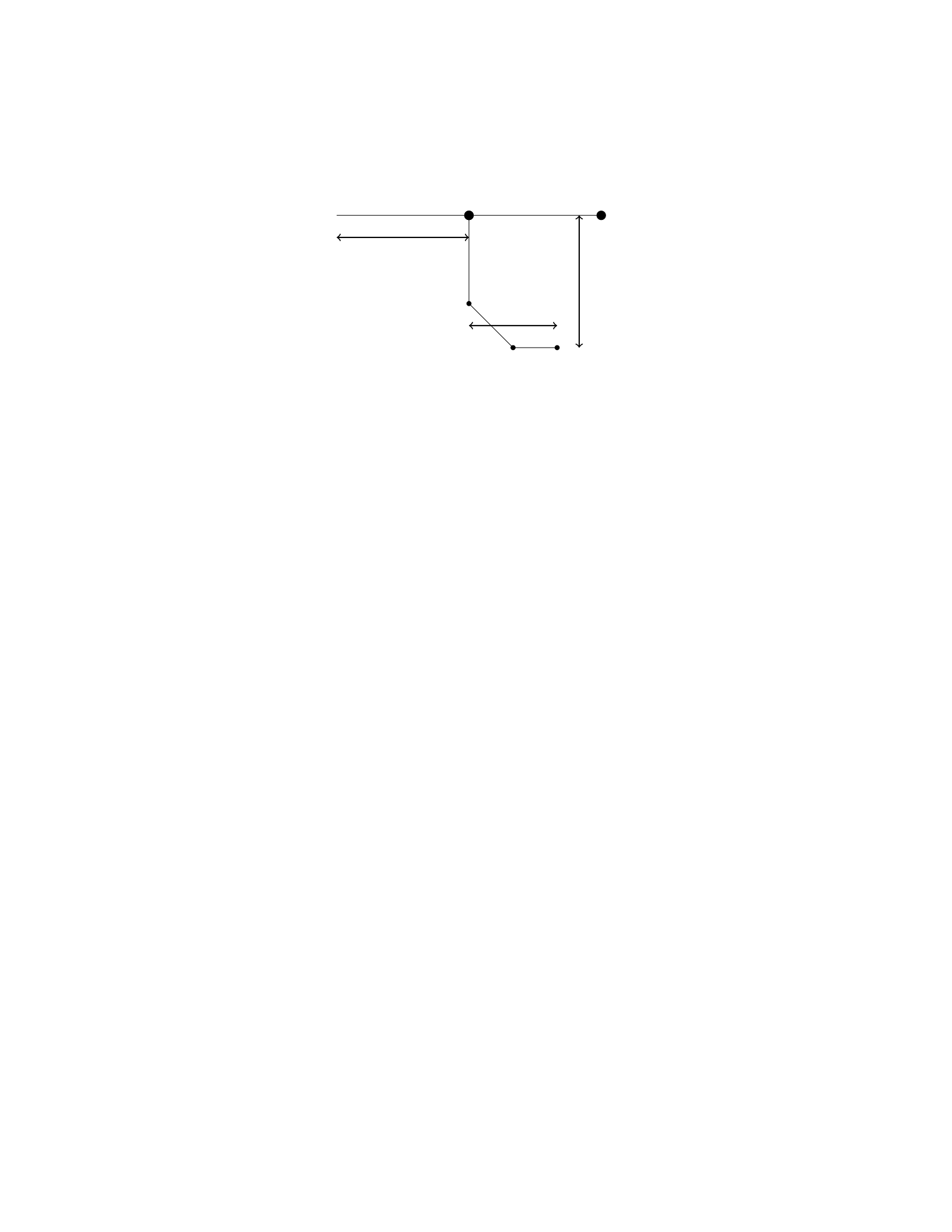
L
2L
x
M2M
Solution
Step 1: We will first draw the free body diagram for the beam. There are three
forces acting on the beam: the weight of the beam (2Mg) acting downward at
the center of the beam, the tension force from the rope (T) acting upward at a
distance xfrom one end, and the reaction force at the support point (N) acting
upward at the pivot.
Step 2: Let’s sum the forces in the vertical direction to find the expression
for the tension T. Taking upward forces as positive, we have:
N−2Mg +T= 0
N= 2Mg −T
Step 3: Next, let’s sum the torques about the pivot point. The torque due
to the force Nis zero since it acts at the pivot. The torque due to the force
2Mg about the pivot is MgL. The torque due to the tension force Tabout the
pivot is T(x+ 2L). The condition for rotational equilibrium gives:
T(x+ 2L) = MgL
Step 4: Now we can solve the two equations we obtained in Step 2 and Step
3 to find the tension T. Substituting N= 2Mg −Tinto T(x+ 2L) = MgL, we
get:
(2Mg −T)(x+ 2L) = MgL
2Mgx + 4MgL −T x −2T L =M gL
T x + 2T L = 2M gx + 4MgL
T(x+ 2L)=2Mg(x+ 2L)
T= 2Mg
Therefore, the tension in the rope is 2Mg.
23
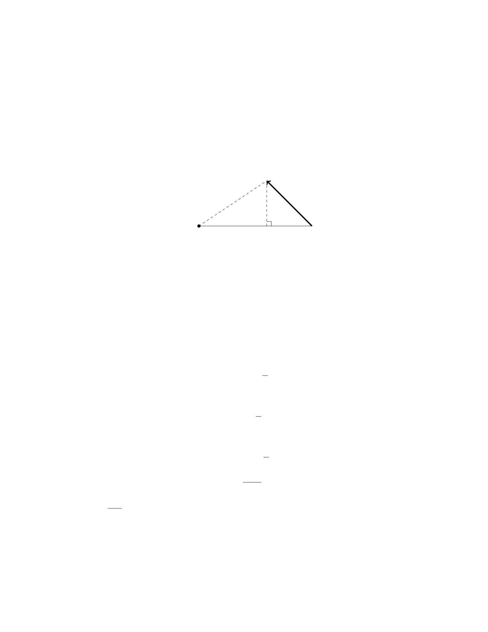
Question 27
Question
A uniform rod of length Land mass Mis pivoted at one end. A force Fis
applied perpendicular to the rod at a distance dfrom the pivot, as shown in the
figure. Find the magnitude and direction of the force needed to hold the rod in
equilibrium.
Pivot
F
Ld
Solution
Step 1: We will begin by drawing a free-body diagram of the rod. Let’s designate
the forces acting on the rod: the force Fat a distance dfrom the pivot, the
weight Mg acting downwards at the center of mass of the rod, and the normal
force Nacting upwards at the pivot point to keep the rod in equilibrium.
Step 2: We will write the torque equation about the pivot point to find the
force Fin terms of known quantities. The torque due to force Fis:
τF=F·d
The torque due to the weight Mg is:
τMg =M g ·L
2
Since the rod is in equilibrium, the sum of the torques must be zero:
F·d−Mg ·L
2= 0
Step 3: Solve for the force F:
F·d=Mg ·L
2
F=MgL
2d
Therefore, the magnitude of the force needed to hold the rod in equilibrium is
MgL
2d. To find the direction of the force, we observe that it must be perpendicular
to the rod and directed outward from the pivot point.
24

Question 28
Question
A uniform, thin rod of length Land mass Mis initially at rest on a frictionless
horizontal surface. A force Fis then applied to the other end of the rod in a
direction perpendicular to the rod. Find the magnitude of the force needed to
make the rod tip lift off the surface.
Solution
1. Draw a Free Body Diagram (FBD):
Let’s consider the forces acting on the rod when the tip is about to lift off.
These forces are: - The force of gravity acting at the center of mass Cof the
rod (mg downwards) - The normal force Nexerted by the surface on the rod -
The external force Fapplied at the other end of the rod
2. Write the Equations for Equilibrium:
For the rod to be in equilibrium, the net force acting on it must be zero and the
net torque about any point must also be zero. We’ll choose the pivot point to
be at the point where the rod is touching the surface.
The net force equation in the vertical direction is:
N=mg
The net torque equation about the pivot point is:
F·L= (MgL/2)
3. Solve for the External Force F:
Substitute N=mg and solve the torque equation for F:
F·L= (MgL/2)
F=MgL
2L
F=Mg
2
Thus, the magnitude of the force needed to make the rod tip lift off the
surface is F=Mg
2.
Question 29
Question
A uniform rod of mass Mand length Lis pivoted at its midpoint. Two masses,
each with mass m, are attached to the ends of the rod. Find the period of small
oscillations around the equilibrium position.
25

Solution
Step 1: Identify the force equations for small oscillations.
The forces acting on mass mon the right side of the pivot are the tension in
the rod, gravity, and the force due to motion. The forces acting on the left side
are similar, except the force due to motion is opposite in direction. We start by
writing the force equation for the right side mass m:
T−mg +F=m¨x
where Tis the tension, gis the acceleration due to gravity, Fis the force due
to motion, and ¨xis the acceleration of the mass.
Step 2: Write the force equation for the left side mass m.
The force equation for the left side mass mis:
T−mg −F=m¨x
Step 3: Determine expressions for the tension and force due to motion.
At equilibrium, the tension is merely supporting the weight, so T=mg.
The force due to motion, F, is equal to −kx, where xis the position of the mass
relative to the equilibrium position.
Step 4: Substitute the expressions for tension and force into the force equa-
tions.
For the right side mass m:
mg −mg −kx =m¨x
−kx =m¨x
−k
mx= ¨x
Step 5: Determine the angular frequency ωof oscillations.
The above equation is the differential equation of simple harmonic motion
with angular frequency ω=qk
m.
Step 6: Calculate the period Tof oscillations.
The period T=2π
ω= 2πpm
k.
Therefore, the period of small oscillations around the equilibrium position
for the system is 2πpm
k.
Question 30
Question
A uniform rod of length Land mass Mis suspended horizontally by two vertical
wires of equal length L, as shown in the figure below. The distance between the
wires is b. What is the tension in each wire?
[Figure: a rod suspended horizontally by two vertical wires of equal length
with distance bbetween them]
26

Solution
Let’s denote the tension in each wire as T.
Step 1: The free-body diagram of the rod shows that the forces acting on
the rod are the tensions in the two wires and the gravitational force acting at
the center of the rod.
Step 2: In the horizontal direction, the tensions must balance the weight of
the rod:
2T=Mg
Step 3: Solving for T, we have:
T=Mg
2
Step 4: So, the tension in each wire is Mg
2.
Question 31
Question
A uniform meter stick of mass 0.2 kg is standing vertically with its lower end
resting on a frictionless horizontal surface. A string is attached to the upper
end and pulled horizontally with a force of 12 N. The coefficient of static friction
between the stick and the surface is 0.6. Determine the tension in the string.
Solution
Step 1: First, let’s analyze the forces acting on the meter stick. There are
three forces to consider: the tension in the string (T) pulling to the right, the
weight of the stick acting downward, and the normal force exerted by the ground
perpendicular to the stick.
Step 2: The weight of the stick can be calculated using the formula Fweight =
mg, where mis the mass and gis the acceleration due to gravity. Given that
m= 0.2 kg and g= 9.8 m/s2, we have Fweight = (0.2 kg)(9.8 m/s2).
Step 3: The normal force is equal in magnitude and opposite in direction to
the weight of the stick when the stick is in equilibrium. Therefore, the normal
force is also Fweight.
Step 4: Since the stick is on the verge of sliding horizontally, the maximum
static friction force is µsN, where µsis the coefficient of static friction (0.6) and
Nis the normal force. In this case, the static friction force is acting to the left.
Step 5: For the stick to remain in equilibrium, the net force in the horizontal
direction must be zero. This means that the tension in the string must be equal
in magnitude to the friction force. So we have T=µsN.
Step 6: Substituting N=Fweight and µs= 0.6 into the equation T=µsN,
we get T= 0.6·[0.2 kg ·(9.8 m/s2)].
Step 7: Calculating this expression gives us the tension in the string:
27
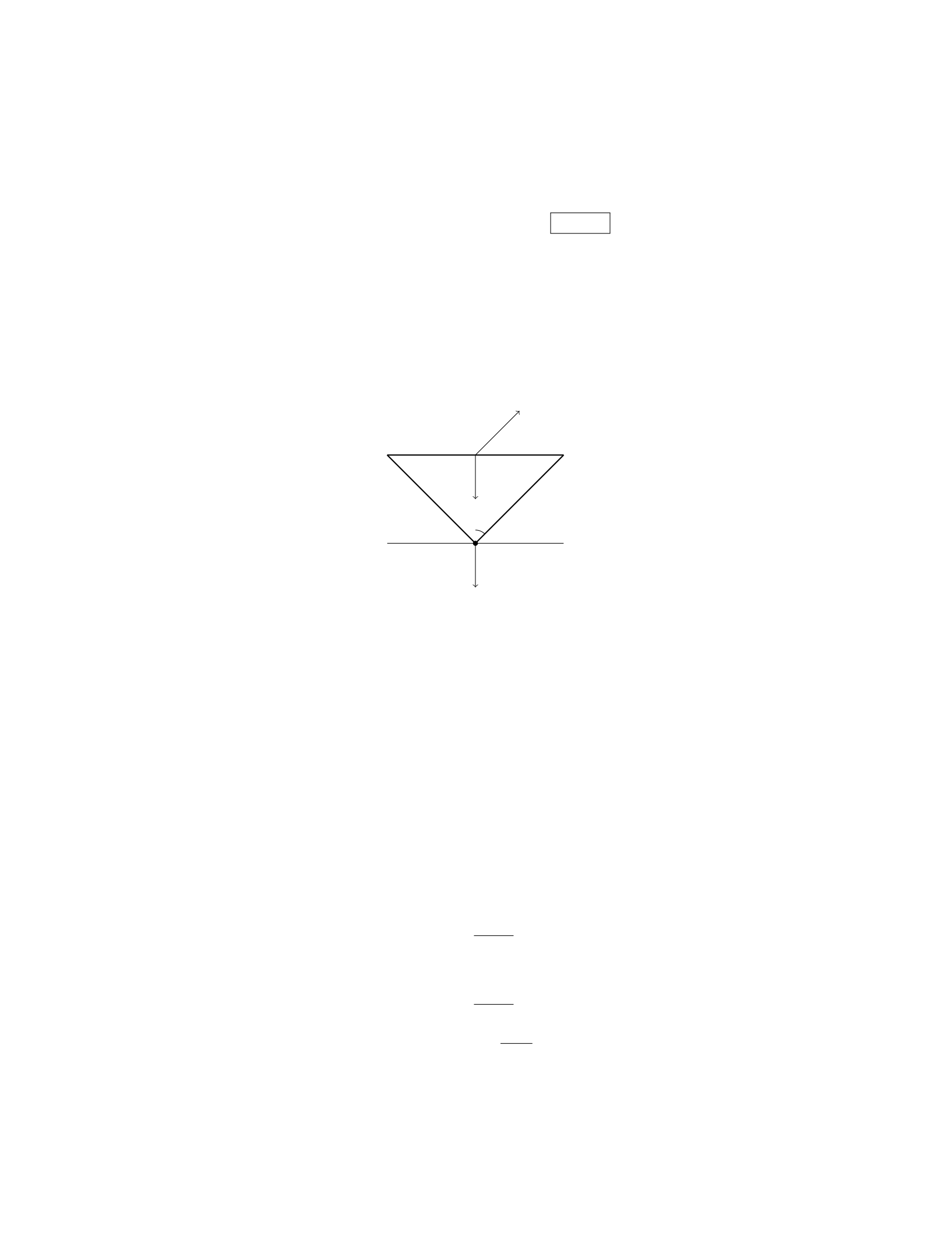
T= 0.6·[0.2 kg ·(9.8 m/s2)] = 1.176 N
Question 32
Question
A uniform rod of length Land mass Mis supported horizontally by two vertical
strings, as shown in the diagram below. The rod makes an angle θwith the
horizontal. Determine the tension in each string in terms of L,M, and θ.
Mg
θ
T1
T2
Solution
Step 1: Setup the following equations: - Sum of forces in the x-direction:
T2cos θ−T1cos θ= 0 - Sum of forces in the y-direction: T1sin θ+T2sin θ−M g =
0
Step 2: Solve equation (1) for T2in terms of T1:
T2=T1
Step 3: Substitute the expression for T2from Step 2 into equation (2):
T1sin θ+T1sin θ−Mg = 0
Step 4: Simplify equation from Step 3:
2T1sin θ=Mg
Step 5: Solve for T1:
T1=Mg
2 sin θ
Step 6: The tension in each string is equal, so T2=T1:
T2=Mg
2 sin θ
Therefore, the tension in each string is M g
2 sin θ.
28

Question 33
Question
A uniform horizontal beam of length Land mass Mis supported at one end by
a pivot and has a weight (W=Mg) hanging from the other end. A block of
mass mis placed a distance dfrom the pivot as shown in the figure below. If
the block is at rest, find the force exerted by the pivot on the beam.
beam_pivot.png
Solution
Step 1: First, let’s draw a free-body diagram for the beam, showing all the
forces acting on it. The forces acting on the beam are its weight acting at the
center of mass, the normal force exerted by the pivot, and the force exerted by
the block.
Step 2: Since the beam is at rest, the sum of torques about any point must
be zero. For simplicity, we will take torques about the pivot point.
The torque due to the weight of the beam is zero since it acts at the pivot
point.
Step 3: The torque due to the block mabout the pivot is m·g·d(clockwise).
The torque due to the normal force exerted by the pivot is zero since it acts
at the pivot point.
Step 4: Therefore, the sum of torques is equal to zero:
m·g·d= 0
Step 5: Solving for the normal force Nexerted by the pivot on the beam:
N=m·g·d
L
Hence, the force exerted by the pivot on the beam is m·g·d
L.
Question 34
Question
A steel beam of length 5.0 m is supported by a hinge at one end and a vertical
cable attached to the other end. The beam has a mass of 500 kg. If the beam
makes an angle of 30 degrees with the horizontal, what is the tension in the
cable? (Assume g = 9.81 m/s2)
29

Solution
Step 1: First, let’s draw a diagram of the situation to visualize the forces acting
on the beam. We have the weight of the beam acting downward at the center,
the tension in the cable pulling upward at an angle of 30 degrees with the
vertical, and a normal force acting horizontally at the hinge.
Step 2: We can start by calculating the weight of the beam using the formula:
Fgravity =m·g, where mis the mass of the beam and gis the acceleration due
to gravity. Fgravity = (500 kg) ·(9.81 m/s2) = 4905 N
Step 3: Next, we can resolve the force due to gravity into its horizontal and
vertical components. The vertical component will counteract the tension in the
cable. The vertical component of the weight is Fgravity ·sin(30◦). Fvertical =
4905 N ·sin(30◦) = 2452.5 N
Step 4: Since the beam is in equilibrium, the vertical component of the
weight must be balanced by the tension in the cable. Therefore, the tension
in the cable is equal to the vertical component of the weight. T=Fvertical =
2452.5 N
Step 5: Therefore, the tension in the cable is 2452.5 N when the beam makes
an angle of 30 degrees with the horizontal.
Question 35
Question
A uniform meterstick of mass 0.20 kg is supported horizontally by two vertical
strings, one at the 0.10 m mark and the other at the 0.80 m mark. A mass of
0.40 kg is hung from the 0.50 m mark. Calculate the tension in each string.
Solution
Step 1: Draw free body diagrams for the meterstick and the hanging mass. For
the meterstick, we have two tensions acting vertically upwards at the 0.10 m
and 0.80 m marks, and the weight of the meterstick acting downwards at its
center of mass. For the hanging mass, we have the tension in the string acting
upwards and the weight of the mass acting downwards.
Step 2: Write out the equations of equilibrium for each object. For the
meterstick: XFy=T1+T2−mg = 0
T1+T2=mg
For the hanging mass:
XFy=T2−mg′= 0
T2=mg′
where mis the mass of the meterstick, gis the acceleration due to gravity, and
g′is the mass of the hanging mass times the acceleration due to gravity.
30

Step 3: Substitute m= 0.20 kg, g= 9.8 m/s2,g′= 0.40 ×9.8 m/s2, and
solve the system of equations to find T1and T2.
Substituting, we get:
T1+T2= 0.20 ×9.8
T2= 0.40 ×9.8
Solving these equations simultaneously, we get:
T1+ 0.40 ×9.8=0.20 ×9.8
T1+ 3.92 = 1.96
T1= 1.96 −3.92
T1=−1.96 N
T2= 0.40 ×9.8
T2= 3.92 N
Therefore, the tension in the string at the 0.10 m mark is −1.96 N (indicating
it’s downward) and the tension in the string at the 0.80 m mark is 3.92 N.
31

