


PHYS 231 - UNIVERSITY PHYSICS I
- Equilibrium and Elasticity
Question Bank - Set 7
Liberty University
Question 1
Question
A uniform ladder of length Land mass Mrests against a smooth wall, making
an angle θwith the horizontal floor. Find an expression for the normal force
exerted by the floor on the ladder, in terms of M,L,θ, and any other relevant
constants.
Solution
Step 1: Draw a free-body diagram of the ladder.
Let’s denote the following: - Nf: Normal force from the floor - Nw: Normal
force from the wall - f: Force of friction - W: Weight of the ladder - T: Tension
in the ladder
Now, setting up the equilibrium equations for the ladder in the vertical (y)
direction:
Nf+Nw−Wcos(θ) = 0
Step 2: Analyze the forces in the horizontal direction.
In the horizontal (x) direction, we have:
T−f= 0 (no horizontal acceleration)
Step 3: Freed the static friction, f, is given by f=µsNf, where µsis the
coefficient of static friction.
Step 4: Since the ladder is uniform, we can find the center of mass at L/2
from the bottom. The weight, W, acts at this point.
Step 5: Substitute the expressions for the normal force from the wall, Nw=
Wsin(θ), and the weight, W=Mg into the vertical equilibrium equation.

Nf+Mg sin(θ)−Mg cos(θ)=0
Step 6: Solve for Nfto obtain the expression for the normal force exerted
by the floor on the ladder:
Nf=Mg(cos(θ)−sin(θ))
Question 2
Question
A uniform beam of length Land mass Mis supported by two cables, one at
each end. The tension in the left cable is twice the tension in the right cable.
If the beam is in equilibrium and the cables make angles of θand ϕwith the
horizontal, respectively, determine the masses of the cables.
Solution
Step 1: We analyze the forces acting on the beam. Let TLbe the tension in
the left cable and TRbe the tension in the right cable. The forces acting on
the beam in the vertical direction are: - The weight of the beam Mg acting
downward. - The vertical components of the tension in the left and right cables,
which are TLcos θand TRcos ϕrespectively.
Since the beam is in equilibrium, the sum of the vertical forces must be zero:
TLcos θ+TRcos ϕ=Mg (1)
Step 2: Next, we analyze the torque about the left end of the beam. The
torque due to the weight of the beam is zero since it acts at the center of the
beam. The torques due to the tensions in the cables are: - The torque due to
the tension in the left cable is TLsin θ·L
2, which produces a counterclockwise
torque. - The torque due to the tension in the right cable is TRsin ϕ·L
2, which
produces a clockwise torque.
For rotational equilibrium, the sum of the torques must be zero:
TLsin θ·L
2=TRsin ϕ·L
2(2)
Step 3: Now we use the fact from the problem that TL= 2TR:
2TRcos θ+TRcos ϕ=Mg (3)
2TRsin θ=TRsin ϕ(4)
Step 4: Solving equations (3) and (4) simultaneously, we find:
2 sin θcos θ= sin ϕcos ϕ
2 sin 2θ= sin 2ϕ
Step 5: The masses of the cables can be found by using the relationships
ML=TL
gand MR=TR
g, where gis the acceleration due to gravity.
2

Question 3
Question
A uniform wooden beam of length Land mass Mis supported horizontally by
a hinge at one end and by a vertical rope at the other end. The beam makes
an angle θwith the horizontal. Find the tension in the rope.
Solution
Step 1: We begin by drawing a free body diagram of the beam. There are three
forces acting on the beam: the weight Mg acting at the center of mass, the
normal force Nacting at the hinge, and the tension Tacting at the rope. The
beam makes an angle θwith the horizontal.
Step 2: We can write out the force equations in the xand ydirections. In
the xdirection, the net force is zero (Fx= 0), and in the ydirection, the net
force is zero (Fy= 0). The equations are:
ΣFx=−Nsin θ= 0
ΣFy=Ncos θ−Mg −T= 0
Step 3: From the first equation, we find that N= 0 or sin θ= 0. Since the
beam is not in free fall, we have N= 0, so sin θ= 0 and θ= 0◦.
Step 4: Substituting θ= 0◦into the second equation, we find:
Ncos 0 −Mg −T= 0
Simplifying, we get:
N−Mg −T= 0
Step 5: Solving for the tension T, we have:
T=N−Mg
Step 6: Since N=Mg, we get:
T= 0
Therefore, the tension in the rope is zero.
Question 4
Question
A 2 kg box sits on a horizontal tabletop. The coefficient of static friction between
the box and the table is 0.6. A horizontal force of 12 N is applied to the box.
Find the magnitude of the smallest additional force that must be applied to the
box in order to make it move.
Solution
Step 1: Draw a free-body diagram of the box. Step 2: Identify the forces acting
on the box. These include the gravitational force (mg), the normal force (N),
the horizontal applied force (Fapplied), and the force of static friction (fs). Step
3: Write the equilibrium equation in the horizontal direction. The equation
3

is PFx= 0. Step 4: In the horizontal direction, the forces acting are the
applied force (Fapplied) to the right, and the force of static friction (fs) to the
left. So we have Fapplied −fs= 0. Step 5: The force of static friction can be
calculated using the equation fs=µsN. Given that µs= 0.6 and N=mg, we
have fs= 0.6mg. Step 6: Substitute the expression for fsinto the equilibrium
equation and solve for the minimum applied force needed to overcome static
friction. We get Fapplied = 0.6mg = 0.6(2)(9.8) = 11.76 N. Therefore, the
magnitude of the smallest additional force that must be applied to the box in
order to make it move is 0.24 N.
Question 5
Question
A cylindrical steel rod of length 2.0 m and diameter 2.0 cm is hung vertically
from the ceiling. The Young’s modulus for steel is 2.0×10¹¹ N/m2. If the
rod stretches by 0.50 mm under its own weight, what is the mass of the rod?
(Assume the rod is a uniform solid cylinder and neglect any effects of air resis-
tance.)
Solution
Step 1: Determine the cross-sectional area of the steel rod. The cross-sectional
area of a cylinder can be calculated using the formula:
A=πr2
Given that the diameter of the rod is 2.0 cm, the radius rcan be calculated as:
r=2.0 cm
2= 1.0 cm = 0.01 m
Thus, the cross-sectional area is:
A=π(0.01 m)2= 3.14 ×10⁻⁴m2
Step 2: Calculate the weight of the rod using the force equation. The weight
mg of the rod is equivalent to the force causing it to stretch. This force is given
by Hooke’s Law:
F=k∆L
where kis the spring constant (Young’s modulus) and ∆Lis the change in
length. Using this equation:
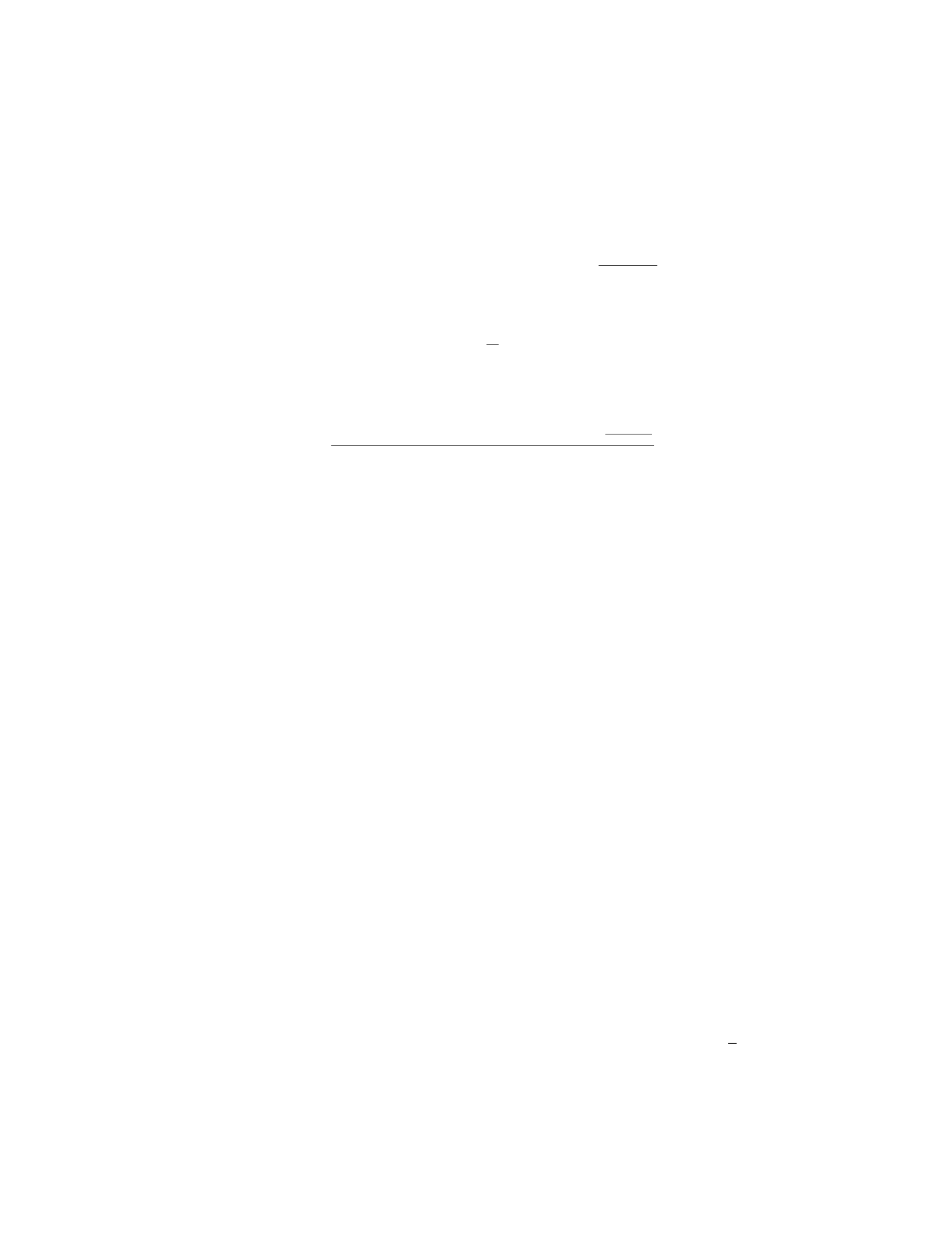
F=A·k·L
L0
4
Given that L= 0.50 mm = 0.0005 m, and the Young’s modulus k= 2.0×10¹¹
N/m2, the force can be calculated as:
F= (3.14 ×10⁻⁴m2)×(2.0×1011 N/m2)×0.0005 m
2.0 m
Step 3: Calculate the mass of the rod using the weight. Since F=mg, we
can solve for the mass m:
m=F
g
where g= 9.81 m/s2is the acceleration due to gravity. Substituting the value
of Finto the equation:
m=(3.14 ×10⁻⁴m2)×(2.0×1011 N/m2)×0.0005 m
2.0 m
9.81 m/s2
Therefore, the mass of the rod is calculated as shown above.
Question 6
Question
A uniform beam of length Land mass Mis supported by a vertical cable
attached to one end of the beam. The other end of the beam is in contact with
a frictionless wall. The cable makes an angle θwith the beam. Find the tension
in the cable.
Solution
Step 1: First, draw a free-body diagram of the beam. Label all the forces acting
on the beam. There are three forces acting on the beam: the gravitational
force Mg acting downward at the center of mass, the normal force Nacting
perpendicular to the wall at the point of contact, and the tension Tacting in
the direction of the cable. The angle between the beam and the horizontal is
also θ.
Step 2: Break down the gravitational force Mg into components parallel and
perpendicular to the beam. The component parallel to the beam is Fparallel =
Mg sin(θ), and the component perpendicular to the beam is Fperpendicular =
Mg cos(θ).
Step 3: The beam is in equilibrium, so the sum of the forces in the vertical
direction is zero. This gives us the equation:
Tcos(θ) = Mg cos(θ)
Step 4: The beam is also in rotational equilibrium about the point of contact
with the wall. The torque due to the tension Tmust balance the torque due to
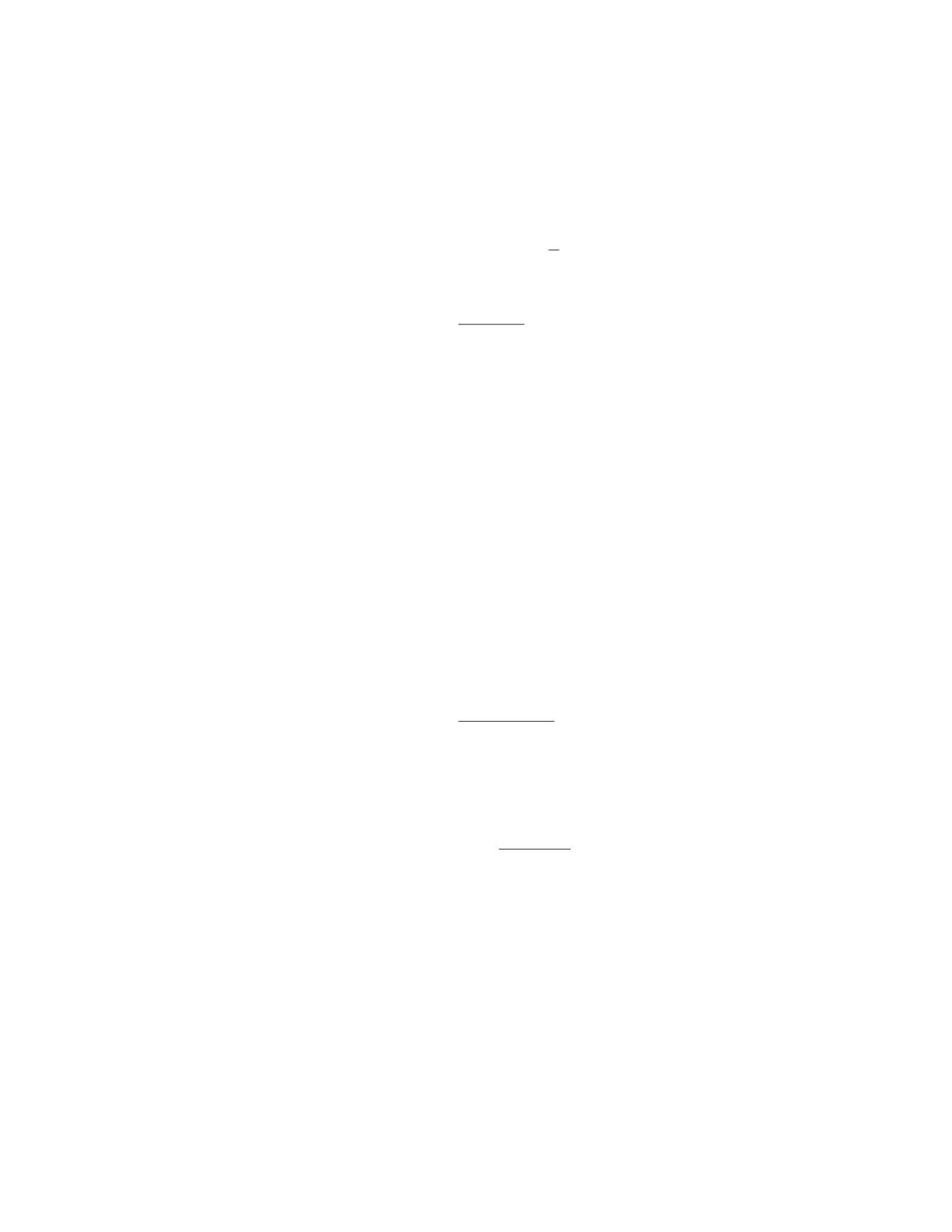
the gravitational force. The torque due to the gravitational force is Fparallel ·L
2,
5
and the torque due to the tension is Tsin(θ)·L. Setting these torques equal
gives us:
Tsin(θ)·L=Fparallel ·L
2
Step 5: Substituting the expression for Fparallel into the torque equation and
solving for T, we get:
T=Mg sin(θ)
2 cos(θ)
Question 7
Question
A uniform meterstick of mass 0.20 kg is supported horizontally by a string
attached at the 10 cm mark. A weight of 0.50 N hangs from the end of the stick
at the 100 cm mark. What is the tension in the string and the force exerted on
the stick at the fulcrum?
Solution
Step 1: Find the tension in the string using the torque equation. Let’s define the
clockwise torque as positive. The torques due to the weight of the meterstick
and the weight hanging from the end must balance each other out to maintain
equilibrium. The torque equation is:
Tstring ·0.10 m = 0.50 N ·1.00 m
Solving for the tension Tstring:
Tstring =0.50 N ·1.00 m
0.10 m
Step 2: Calculate the force exerted on the stick at the fulcrum. Since the
stick is in equilibrium, the sum of all forces in the vertical direction must be
zero. Let Ffulcrum be the force exerted on the stick at the fulcrum.
Ffulcrum = 0.20 kg ·9.81 m/s2−0.50 N
Therefore, the tension in the string is 0.50 N·1.00 m
0.10 m = 5.00 N, and the force
exerted on the stick at the fulcrum is 0.20 kg ·9.81 m/s2−0.50 N = 1.82 N.
Question 8
Question
A uniform rod of length Land mass Mis suspended horizontally from one end.
Two forces, each of magnitude F, are applied at points 2L/3 and 5L/6 from the
end where the rod is suspended. Determine the tension in the rod at the point
of suspension.
6

Solution
Step 1: To find the tension at the point of suspension, we need to consider the
net torque acting on the rod about that point to ensure equilibrium.
Step 2: Let Tbe the tension at the point of suspension. The forces Fapplied
at 2L/3 and 5L/6 create a torque about the suspension point in the clockwise
direction. Using the lever arm D:
D=L
6and D′=L
2.
Step 3: The torque due to the force Fat 2L/3 is −F·L
6(since it is trying
to rotate counterclockwise).
Step 4: The torque due to the force Fat 5L/6 is −F·L
2(also trying to
rotate counterclockwise).
Step 5: For equilibrium, the net torque about the suspension point must be
zero:
0 = −F·L
6−F·L
2+T·L.
Step 6: Solving the equation above for Tgives:
T=F
2.
Step 7: Therefore, the tension at the point of suspension is half of the force
applied (T=F
2).
Question 9
Question
A thin rod of length Land mass Mis hanging vertically from a fixed point. A
block of mass mis attached to the bottom end of the rod. The rod remains in
equilibrium, making an angle θwith the vertical. Calculate the tension in the
rod and the normal force on the block.
Solution
1. Free body diagram:
Let’s draw the free body diagram for both the rod and the block.
For the rod: - The forces acting on the rod are the tension Tin the rod, the
weight of the rod Mg acting at the center of mass, and the normal force Nat
the fixed point. - The vertical component of tension balances the weight of the
rod and the horizontal component of tension balances the horizontal component
of the normal force.
For the block: - The forces acting on the block are the tension Tin the rod
and the weight of the block mg. - The tension Tacts at an angle θwith the
vertical.
7

2. Equilibrium for the rod:
For the rod to be in equilibrium vertically:
Tcos θ=Mg
For the rod to be in equilibrium horizontally:
Tsin θ=N
3. Equations of equilibrium for the block:
In the vertical direction:
T=mg
4. Solve for Tand N:
From the equation for equilibrium in the vertical direction for the rod:
T=Mg
cos θ
From the equilibrium equation for the block:
T=mg
Substitute the expression for Tin terms of mg into the horizontal equilibrium
equation for the rod:
mg sin θ=N
Therefore, the tension in the rod is T=M g
cos θand the normal force on the
block is N=mg sin θ.
Question 10
Question
A block of mass mis hanging from a vertical spring, causing it to stretch by
a distance xfrom its equilibrium position. The spring constant is kand the
acceleration due to gravity is g. Find the elastic potential energy stored in the
spring due to the block.
Solution
Step 1: The force exerted by gravity on the block is given by Fgravity =mg.
The force exerted by the spring on the block is equal in magnitude but opposite
in direction to the force exerted by gravity, so Fspring =−mg.
Step 2: From Hooke’s Law, the force exerted by a spring is given by Fspring =
−kx, where xis the displacement of the spring from its equilibrium position.
Step 3: Setting Fspring =Fgravity, we have −mg =−kx. Solving for x, we
find that x=mg
k.
8

Step 4: The elastic potential energy stored in the spring is given by P Eelastic =
1
2kx2. Substituting the value of xinto this equation, we get P Eelastic =1
2kmg
k2.
Step 5: Simplifying the expression, we have P Eelastic =1
2m2g2/k. Thus, the
elastic potential energy stored in the spring due to the block is 1
2m2g2/k .
Question 11
Question
A uniform beam of length Land mass Mis supported by a hinge at one end
and by a cable that makes an angle θwith the beam at the other end. The cable
exerts a horizontal force Fon the beam. Determine the tension in the cable.
Solution
Step 1: Begin by drawing a free-body diagram of the beam, including all the
forces acting on it. We have gravity (Mg) acting downwards at the center of
mass of the beam, the normal force (N) acting upwards at the hinge, and the
tension in the cable (T) acting at an angle θwith respect to the horizontal.
Step 2: Decompose the tension Tinto vertical and horizontal components. The
horizontal component of Tis Tcos θand the vertical component is Tsin θ. Step
3: Write the equilibrium equations for the beam in both the horizontal and
vertical directions. In the horizontal direction, we have Tcos θ=Fsince the
horizontal forces must balance each other. In the vertical direction, we have
N=Mg +Tsin θsince the vertical forces must also balance. Step 4: To find
the tension T, we need to eliminate Nfrom our equations. We can do this by
expressing Nin terms of M,g, and L, since we are given that the beam has a
length Land mass M. Since the beam is uniform, the center of mass will be
at L/2 from the hinge. Thus, N×L/2 = Mg ×L/2. This gives us N=Mg.
Step 5: Substitute N=Mg back into the equation N=Mg +Tsin θand solve
for T. We get T=M g sin θ. Step 6: Therefore, the tension in the cable is
T=Mg sin θ.
Question 12
Question
A uniform rod of mass Mand length Lis suspended horizontally at one end by
two vertical strings of length Las shown in the figure. The rod makes an angle
θwith the horizontal. What is the tension Tin each string?
θ
9
Solution
Step 1: Draw forces acting on the rod and write equilibrium equations. Let T
be the tension in each string. The forces acting on the rod are the gravitational
force Mg acting downward at the center of the rod and the tension forces T
acting upwards in the strings. In the vertical direction, the net force must be
zero:
2Tcos θ=Mg
Step 2: Solve for the tension T. Solving for Tin the equation above:
T=Mg
2 cos θ
Therefore, the tension in each string is Mg
2 cos θ.
Question 13
Question
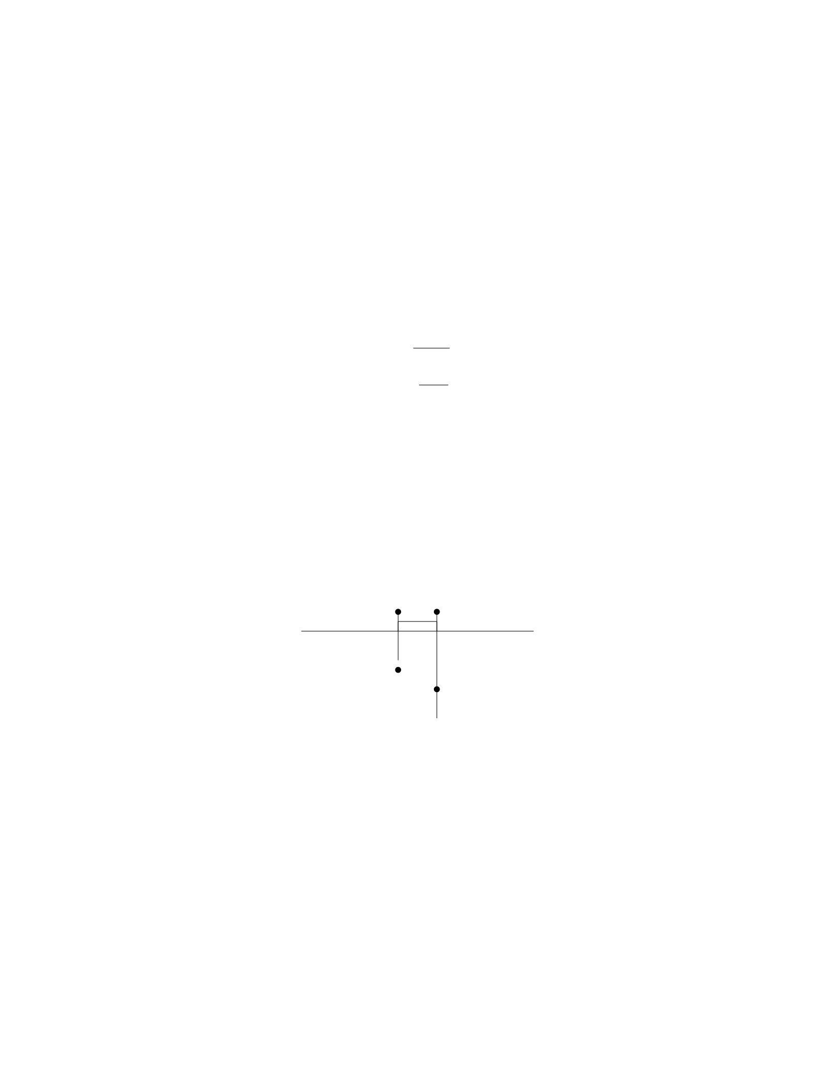
A uniform rod of length Land mass Mis suspended horizontally by two vertical
strings, one attached at the end of the rod and the other attached a distance
dfrom the end (see diagram below). The tension in the string attached at the
end is T1and the tension in the string attached at a distance dfrom the end is
T2. What are the tensions T1and T2in terms of M,L,d, and g(acceleration
due to gravity)?
T1T2
m1
m2
Solution
Let’s denote the tension in the string attached at the end of the rod as T1and
the tension in the string attached at a distance dfrom the end as T2.
Step 1: Set up equilibrium equations
For the vertical direction: The net force in the vertical direction must be
zero in order for the rod to be in equilibrium.
T1+T2=Mg (1)
For the torque equation: In order for the rod to be in equilibrium, the total
torque about any point must be zero. Let’s choose the point where T1is applied
as the pivot point.
10

Torque due to T1: 0
Torque due to T2:T2·Lsin θ2
The torque equilibrium equation is:
T2·Lsin θ2= 0
Since θ2= tan−1d
L
2= tan−12d
L, the torque equation becomes:
T2·L·sin tan−12d
L= 0
T2·2d= 0
T2= 0 (2)
Step 2: Solve for tensions T1and T2
From equation (1) and equation (2), we have:
T1+ 0 = Mg
T1=Mg
Therefore, the tension in the string attached at the end of the rod is T1=Mg
and the tension in the string attached at a distance dfrom the end is T2= 0.
Question 14
Question
A uniform beam of length Land mass Mis supported by a pivot at one end
and a rope at a distance dfrom the pivot. The beam makes an angle θwith
the horizontal. If the tension in the rope is T, what is the force exerted by the
pivot on the beam?
Solution
1. We will start by drawing a free-body diagram of the beam. The forces acting
on the beam are the force of gravity Mg acting at the center of mass, the tension
Tin the rope, and the force Fpivot exerted by the pivot.
2. Since the beam is in rotational equilibrium, the sum of the torques acting
on it must be zero. Taking the pivot point as the axis of rotation, the torque
due to the force of gravity is L
2Mg sin θ, the torque due to the tension is dT sin θ,
and the torque due to the pivot force is zero.
3. Setting the sum of the torques equal to zero, we have:
L
2Mg sin θ−dT sin θ= 0
4. Solving for the pivot force Fpivot, we have:
Fpivot =L
2Mg −dT
5. Now, we need to find an expression for the tension Tin the rope. This
can be done by considering the equilibrium of the forces in the vertical direction:
11
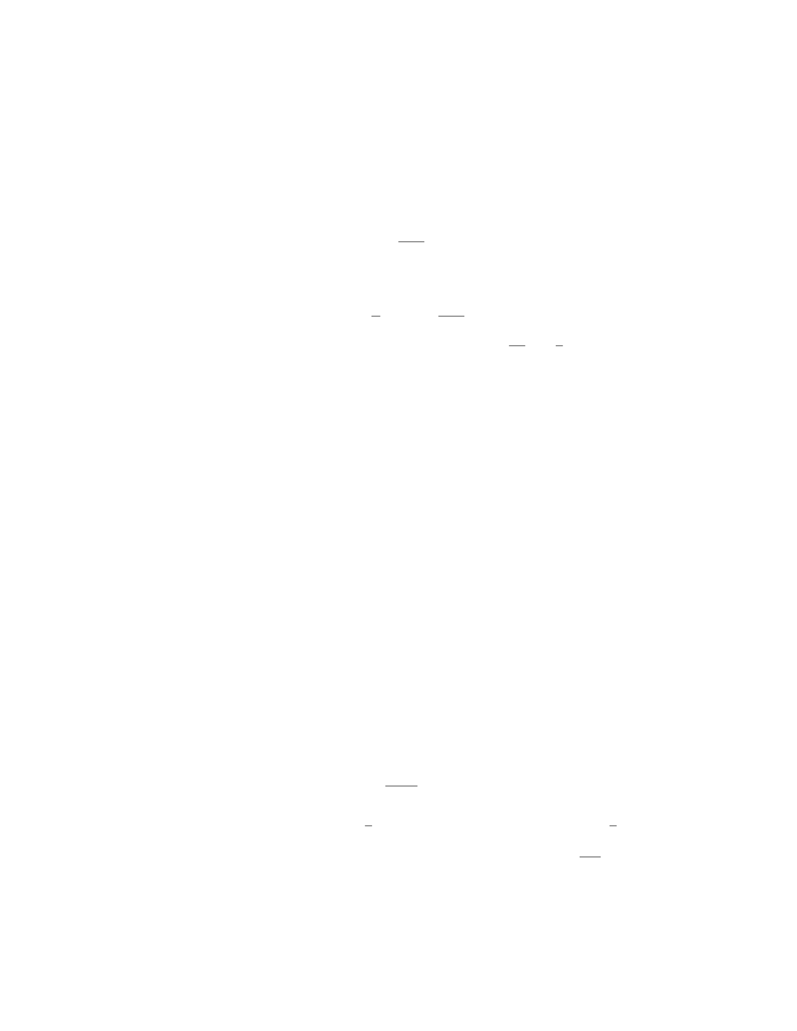
Tcos θ=Mg
6. Solving for T, we get:
T=Mg
cos θ
7. Substituting this expression for Tinto the equation for the pivot force,
we have:
Fpivot =L
2Mg −dMg
cos θ
8. Thus, the force exerted by the pivot on the beam is M g
2(2 −d
Lsec θ).
Question 15
Question
A uniform rod of length Land mass Mis suspended vertically from a hinge
attached to the ceiling. A horizontal force Fis applied at one end of the rod
causing the rod to rotate slightly. Determine the magnitude and direction of
the force Fneeded to maintain equilibrium.
Solution
Let’s denote the distance from the hinge to the center of mass of the rod as
x, and the angle that the rod makes with the vertical as θ. The gravitational
force acting on the rod is M g acting at the center of mass. The force Facts
horizontally at one end of the rod. In order to maintain equilibrium, the torque
due to Fmust balance the torque due to gravity.
Step 1: Find the torque due to the gravitational force. The torque due to
the gravitational force about the hinge is given by τgravity =x(Mg) sin θ.
Step 2: Find the torque due to the force F. The torque due to the force F
is τF=F(L−x) sin θ.
Step 3: Set up the condition for rotational equilibrium. For rotational
equilibrium, the sum of torques must be zero. Thus, we have:
τgravity =τF
x(Mg) sin θ=F(L−x) sin θ
Solving for F, we get:
F=x
L−xMg
Step 4: Analyze the direction of the force F. The direction of the force F
depends on the value of x. If x < L
2, then Fpoints towards the hinge. If x > L
2,
then Fpoints away from the hinge.
Thus, the magnitude of the force Fneeded to maintain equilibrium is x
L−xMg,
and the direction depends on the value of x.
12

Question 16
Question
A rod of length L, cross-sectional area A, and Young’s modulus Yis suspended
vertically from one end. A force Fis applied horizontally at the other end. Find
the extension of the rod.
Solution
Step 1: Begin by drawing a free-body diagram of the rod. The weight of the
rod acts downward at the midpoint, the force Facts horizontally at the other
end, and the tension Tacts upward at the point where the rod is suspended.
Step 2: Using equilibrium conditions, set the sum of forces in the horizontal
direction to zero. The only horizontal force is the applied force F. Thus, F= 0.
Step 3: Set the sum of forces in the vertical direction to zero. The vertical
forces are the weight of the rod Wacting downward (which can be split into
two equal forces at the midpoint) and the tension force Tacting upward. The
net vertical force is then T−21
2xAρg = 0, where xis the extension of the
rod and ρis the density of the material.
Step 4: The tension Tcan be expressed as T=A·σ=A·Y·ϵ, where σis
the stress and ϵis the strain. The strain can be expressed as ϵ=x
L.
Step 5: Substitute T=AY ϵ into the equation from Step 3 to get AY x
L=
ρA ·g1
2x.
Step 6: Solve for xto find the extension of the rod. We have x=2ρgL
Y.
Therefore, the extension of the rod under the applied force Fis 2ρgL
Y.
Question 17
Question
A wooden beam of length Land uniform cross-sectional area Ais supported at
one end by a wall and has a weight Wattached at the other end. The beam is
in equilibrium. Calculate the magnitude of the force exerted by the wall on the
beam.
Solution
Step 1: First, we need to draw a free-body diagram of the beam to identify the
forces acting on it.
Step 2: The forces acting on the beam are the weight Wacting downward
at the end of the beam, the force of gravity acting at the center of mass of the
beam, and the force Fexerted by the wall on the beam.
Step 3: Since the beam is in equilibrium, the sum of the forces in the vertical
direction must be zero.
Fwall −W= 0
13

Step 4: We can express the weight Win terms of the mass of the beam m
and the acceleration due to gravity g. The weight is given by W=mg.
Step 5: Since the beam has a uniform cross-sectional area Aand is made of
wood, we can express the mass of the beam in terms of its density ρ, length L,
and cross-sectional area A. The mass is given by m=ρAL.
Step 6: Substituting W=mg and m=ρAL into the equilibrium equation,
we get:
Fwall −ρALg = 0
Step 7: Solving for the force Fwall:
Fwall =ρALg
Therefore, the magnitude of the force exerted by the wall on the beam is
ρALg.
Question 18
Question
A solid block of aluminum, with a volume of 0.05 m3, is submerged in water.
The block is connected to a spring scale and the reading on the scale is 420 N.
The density of aluminum is 2700 kg/m3and the density of water is 1000 kg/m3.
Determine the depth to which the block is submerged in the water.
Solution
Step 1: Find the weight of the aluminum block in air. Given: Density of
aluminum, ρAl = 2700 kg/m3
Volume of aluminum block, VAl = 0.05 m3
Acceleration due to gravity, g= 9.81 m/s2
The weight of the block in air can be found using the formula:
WAl =ρAl ×VAl ×g
Substitute the known values to find WAl:
WAl = 2700 ×0.05 ×9.81 = 1321.5 N
Step 2: Find the buoyant force acting on the block. The buoyant force on
the block is equal to the weight of the water displaced. The weight of the water
displaced can be found using the formula:
Wwater =ρwater ×VAl ×g
Substitute the known values to find Wwater:
Wwater = 1000 ×0.05 ×9.81 = 490.5 N
14
Step 3: Find the net force acting on the block. Since the block is in equilib-
rium, the net force acting on the block is zero. Therefore:
Fnet =WAl −Wwater = 1321.5−490.5 = 831 N
Step 4: Find the depth to which the block is submerged. The spring scale
reading provides the buoyant force acting on the block, which is equal to the
net force. Therefore, the depth to which the block is submerged can be found
using:
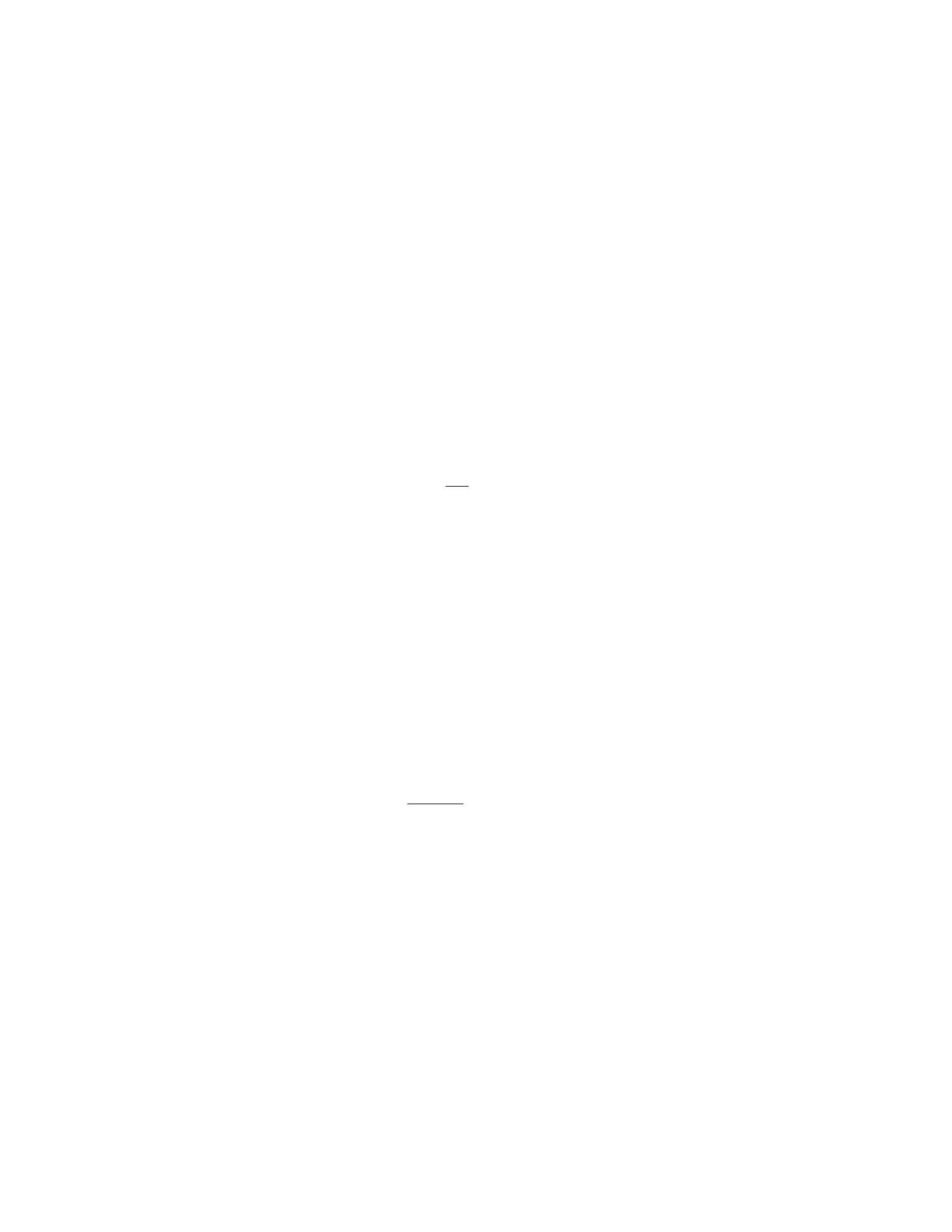
Fnet =k×x
where kis the spring constant and xis the displacement of the block.
Given Fnet = 831 N and k= 420 N, solve for x:
831 = 420 ×x
x=831
420 = 1.98 m
Thus, the block is submerged to a depth of 1.98 m in the water.
Question 19
Question
A steel wire of length 2.0 m and diameter 0.50 mm is stretched until its length
increases by 1.0 cm. If the Young’s modulus of steel is 2.0×10¹¹ N/m2, deter-
mine the stress and strain on the wire.
Solution
Step 1: Calculate the original cross-sectional area of the wire. Given that the
wire has a diameter of 0.50 mm, we can calculate the original radius, r0, as
follows:
r0=0.50 mm
2= 0.25 ×10⁻³m
The original cross-sectional area, A0, is given by:
A0=πr2
0
A0=π(0.25 ×10⁻³)2
A0= 1.96 ×10⁻⁷m2
Step 2: Calculate the final length of the wire. Given that the wire’s length
increases by 1.0 cm, the final length, Lf, is:
Lf= 2.0 m + 0.01 m = 2.01 m
15

Step 3: Calculate the strain in the wire. The strain, ϵ, is given by:
ϵ=∆L
L0
ϵ=0.01 m
2.0 m
ϵ= 5 ×10⁻³
Step 4: Calculate the stress in the wire. The stress, σ, is given by Hooke’s
Law:
σ=E·ϵ
σ= 2.0×10¹¹ N/m2×5×10−3
σ= 1.0×10⁹N/m2
Therefore, the stress in the wire is 1.0×10⁹N/m2and the strain is 5 ×10⁻³.
Question 20
Question
A uniform rod of length Land mass Mis held horizontally so that one end is
against a vertical wall. A block of mass mis placed on the other end of the
rod. The coefficient of static friction between the block and the rod is µs. Find
the minimum coefficient of static friction between the wall and the rod that will
prevent the block from slipping.
Solution
1. Draw a free-body diagram of the rod. Consider the forces acting on the rod:
the force of gravity acting on the rod’s center of mass, the normal force from
the wall, and the force of static friction from the wall.
2. Write the torque equation for the rod about its pivot point at the wall.
The torque due to the gravitational force about this point will cause rotation,
so it must be balanced by the torque due to the normal force from the wall and
the static friction force.
3. The torque due to the gravitational force about the pivot point is −MgL
2
(negative because it tries to make the rod rotate clockwise).
4. The torque due to the normal force about the pivot point is zero since
the normal force passes through the pivot point.
5. Let fbe the static friction force between the rod and the wall. The
torque due to this force is +fL (positive because it tries to make the rod rotate
counterclockwise).
6. The torque equation becomes fL =MgL
2.
7. The friction force needed to prevent slipping is given by fmin =µsN,
where Nis the normal force from the wall.
16

8. To find the minimum force of static friction, we need to analyze the
equilibrium of the block. Write equations for the forces in the vertical and
horizontal directions.
9. In the vertical direction, the normal force from the rod balances the force
of gravity acting on the block. So, N=mg.
10. In the horizontal direction, the force of static friction must balance the
force due to the rod’s weight, which is fmin =µsmg.
11. Substitute N=mg into the torque equation: fmin =M gL
2.
12. Therefore, the minimum coefficient of static friction between the wall
and the rod that will prevent the block from slipping is µs=M
2m.
Question 21
Question
A uniform square plate with side length Land mass Mis suspended from a
wire attached to two of its corners. Determine the tension in the wire when the
plate is in equilibrium.
Solution
We can solve this problem using the concept of torque. In equilibrium, the sum
of the torques acting on the plate must be zero.
Step 1: Identify the forces acting on the plate. There are two forces: the
tension in the wire (T) and the gravitational force acting on the center of the
plate.
Step 2: Choose a pivot point. In this case, let’s choose the bottom-left
corner of the plate as the pivot point.
Step 3: Calculate the torque due to the tension in the wire. The torque
(τT) due to the tension in the wire is given by:
τT=T·L
Step 4: Calculate the torque due to the gravitational force. The gravita-
tional force acts on the center of the plate, which is located L
2away from the
pivot point. The torque (τgravity) due to the gravitational force is given by:
τgravity =Mg ·L
2
Step 5: Set up the torque equation. In equilibrium, the sum of the torques
is zero:
τT−τgravity = 0
T·L−Mg ·L
2= 0
17
Step 6: Solve for the tension in the wire (T):
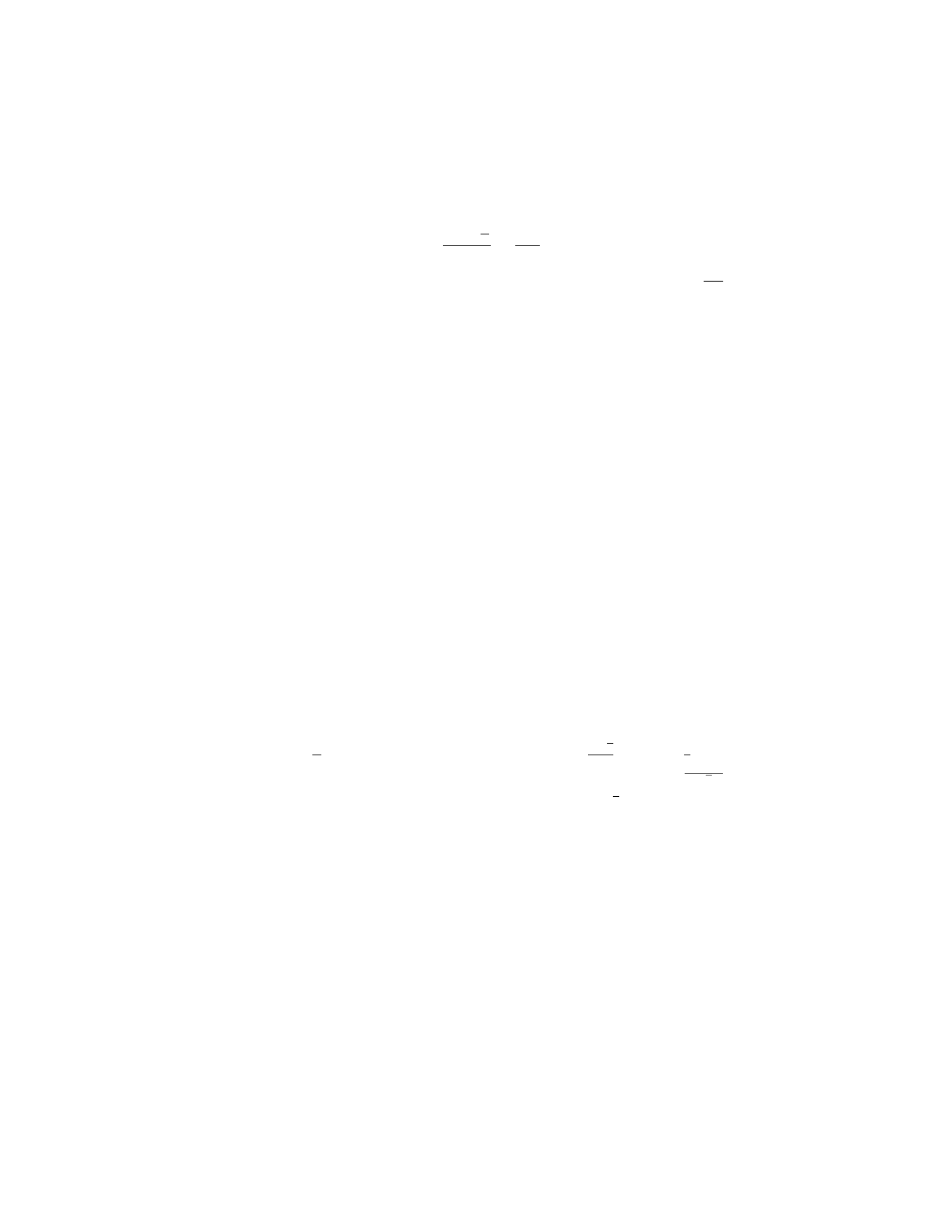
T=Mg ·L
2
L=Mg
2
Therefore, the tension in the wire when the plate is in equilibrium is M g
2.
Question 22
Question
A uniform plank of mass 4 kg and length 3 m is positioned at an angle of 30◦
with the horizontal. One end of the plank rests against a smooth vertical wall,
while the other end is supported by a horizontal rope that makes an angle of 60◦
with the horizontal. Find the tension in the rope and the normal force exerted
on the plank by the wall.
Solution
Step 1: Draw the free-body diagram of the plank.
Let Tbe the tension in the rope, Nbe the normal force exerted by the wall, and Wbe the weight of the plank.
Step 2: Resolve the forces into components.
Resolving vertically: N+Tsin 60◦=W(since the plank is not accelerating vertically)
Resolving horizontally: Tcos 60◦=Wsin 30◦(since the plank is not accelerating horizontally)
Step 3: Determine the weight of the plank.
W=mg = 4 ×9.8 = 39.2 N
Step 4: Solve the equations from Step 2 to find Tand N. From the vertical
equation: N+T
2= 39.2 From the horizontal equation: T√3
2= 39.2×1
2= 19.6
Step 5: Solve for Tand N. From the horizontal equation: T=19.6×2
√3≈
22.6 N Substitute Tinto the vertical equation: N+ 22.6×1
2= 39.2
N= 39.2−11.3 = 27.9 N
Therefore, the tension in the rope is approximately 22.6 N and the normal
force exerted by the wall is approximately 27.9 N.
Question 23
Question
A uniform wooden beam of length Land mass Mis lying horizontally on a
frictionless table. A block of mass mis placed at a distance xfrom one end
of the beam. The block is at rest relative to the beam. What fraction of the
beam’s length is the block located (express your answer in terms of L)?
18

Solution
Step 1: Draw a free-body diagram of the wooden beam.
Step 2: The forces acting on the beam are the weight acting downwards at
the center of mass (1
2L) and the normal force (N) acting upwards at the pivot
point.
Step 3: The net torque about the pivot point must be zero for the beam to
be in equilibrium. The torque produced by the block is xmg, and the torque
produced by the weight of the beam is 1
2L·Mg
2. Setting these torques equal
gives us xmg =1
2L·Mg
2.
Step 4: Solve for xin terms of L:x=L
4.
Step 5: The block is located 1
4of the beam’s length away from the end, so
the fraction of the beam’s length where the block is located is 1
4.
Question 24
Question
A long steel wire with a circular cross-section of radius 1.5 mm is attached
between two rigid supports. The wire is under a tension of 500 N. What is the
maximum allowable length the wire can have without breaking? The Young’s
modulus for steel is 2.0×10¹¹ N/m2.
Solution
Step 1: The stress in the wire can be calculated using the formula:
stress = tension
cross-sectional area
The cross-sectional area of the wire can be calculated using the formula for
the area of a circle:
cross-sectional area = πr2
cross-sectional area = π(1.5×10⁻³)2
Substitute the given values:
cross-sectional area = π(1.5×10⁻³)2≈7.07 ×10⁻⁶m2
Step 2: Now, calculate the stress:
stress = 500
7.07 ×10⁻⁶
stress ≈7.07 ×10⁷N/m2
19
Step 3: The maximum stress a material can handle without breaking is
known as its ultimate tensile strength. For steel, the ultimate tensile strength is
typically around 4 ×10⁸N/m2.
Given that the ultimate tensile strength is 4×10⁸N/m2and the safety factor
is 2 (typical for steel), we can calculate the maximum allowable stress:
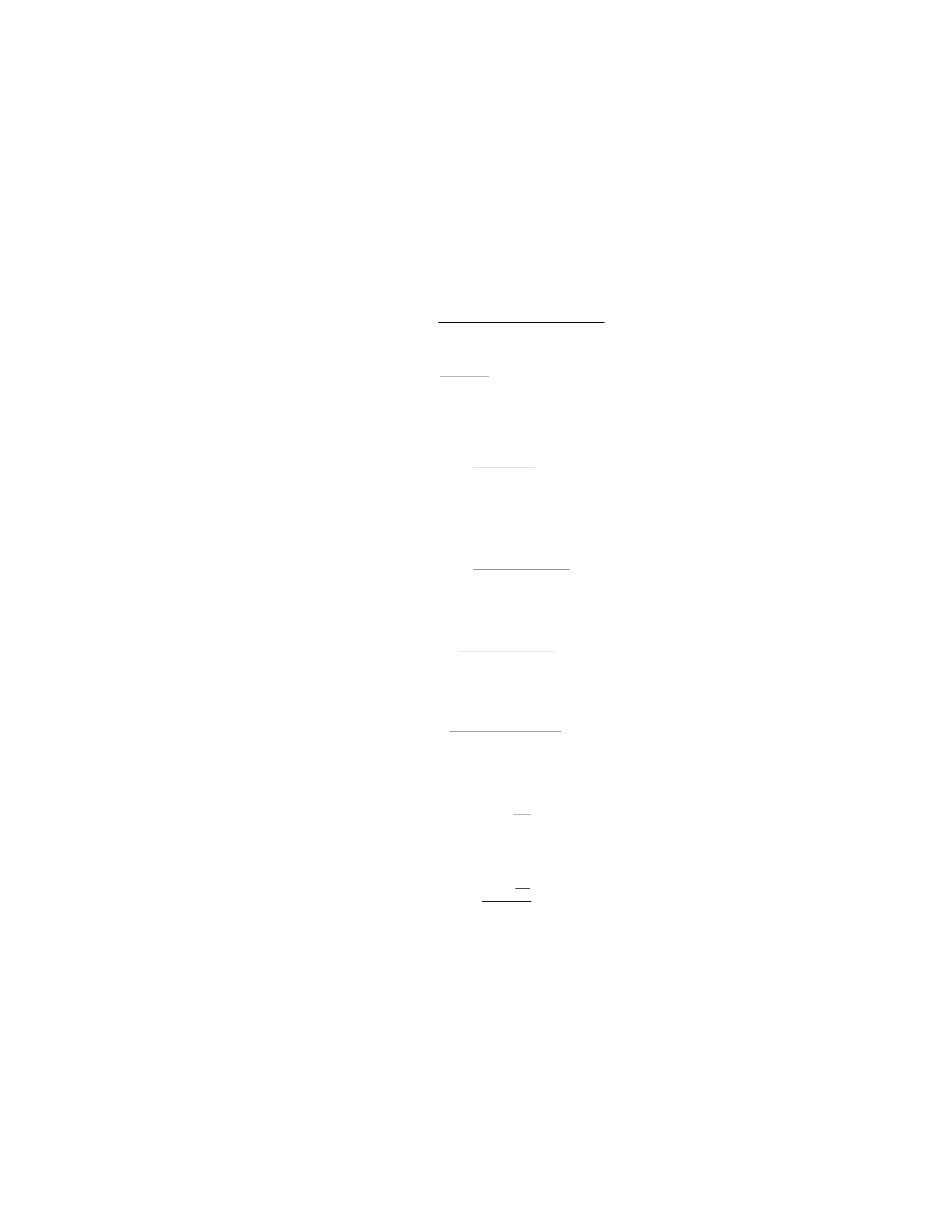
max stress = ultimate tensile strength
safety factor
max stress = 4×10⁸
2= 2 ×10⁸N/m2
Step 4: Now, we can calculate the maximum allowable length the wire can
have without breaking using Hooke’s Law:
stress = Y·strain
length
Since the material will break when the stress reaches the maximum allowable
stress, we can rewrite the formula as:
max stress = Y·max strain
length
Rearranging for length:
length = Y·max strain
max stress
Step 5: The strain can be calculated using the formula:
strain = change in length
original length
The change in length is the maximum length the wire can have, so:
max strain = L
L0
Substitute the known values and solve for the maximum allowable length:
length = Y×L
L0
2×10⁸
Given that Y= 2.0×10¹¹ N/m2,L0is the original length of the wire, and
the maximum allowable stress has been calculated. We just need to find the
original length, L0.
20

Question 25
Question
A uniform beam of length Land mass Mis supported by a pivot at one end,
while a block of mass mis hung from the other end. If the beam makes an angle
θwith the horizontal, determine the tension in the cable holding the block in
terms of m,M,L,g, and θ.
Solution
Step 1: Draw a free-body diagram of the beam.
Step 2: Since the beam is in equilibrium, the sum of forces in the vertical
direction is zero. The forces acting in the vertical direction are the tension T
and the force due to gravity acting at the center of mass of the beam.
Step 3: The force due to gravity acting on the beam is equivalent to the
weight of the beam acting through its center of mass, which is at a distance L/2
from the pivot. The weight of the beam is M g, where gis the acceleration due
to gravity.
Step 4: Using trigonometry, the vertical component of the weight of the
beam is Mg cos(θ), and the horizontal component is Mg sin(θ).
Step 5: The torque about the pivot due to the weight of the beam is given
by τbeam = (M g cos(θ))(L/2). This torque must be balanced by the torque due
to the tension in the cable, which is T(L).
Step 6: Setting up the torque equilibrium equation:
T(L) = MgL
2cos(θ)
Step 7: Thus, the tension in the cable holding the block is:
T=Mg
2cos(θ)
Question 26
Question
A uniform solid cylinder of mass Mand radius Rrolls without slipping down
an inclined plane as shown in the figure. The cylinder starts from rest at a
height habove the bottom of the incline. The incline makes an angle θwith the
horizontal, and the coefficient of kinetic friction between the cylinder and the
incline is µk. Determine the acceleration of the center of mass of the cylinder.
solid_cylinder.png
21

Solution
Step 1: Draw a free body diagram for the cylinder. The forces acting on the
cylinder are its weight W=Mg downward, the normal force Nperpendicular
to the incline, and the frictional force fkparallel to the incline.
Step 2: Break down the weight Winto components perpendicular (W⊥) and
parallel (W||) to the incline. The weight component parallel to the incline will
provide the force driving the cylinder down the incline.
Step 3: The net force acting on the cylinder is the component of the weight
down the incline (W||) minus the frictional force fk:
Fnet =W|| −fk
Step 4: The force acting down the incline is given by
W|| =Wsin θ
Step 5: The frictional force fkcan be calculated using the coefficient of
kinetic friction µk:
fk=µkN
Step 6: The normal force Ncan be calculated by considering the forces
perpendicular to the incline:
N=W⊥=Wcos θ
Step 7: Substitute the expressions for W|| and fkinto the net force equation
to get
Fnet =Mg sin θ−µkMg cos θ
Step 8: The acceleration aof the center of mass of the cylinder can be found
using Newton’s second law:
Ma =Fnet
Step 9: Substitute the expression for Fnet into the acceleration equation:
Ma =Mg sin θ−µkMg cos θ
Step 10: Solve for the acceleration a:
a=g(sin θ−µkcos θ)
Question 27
Question
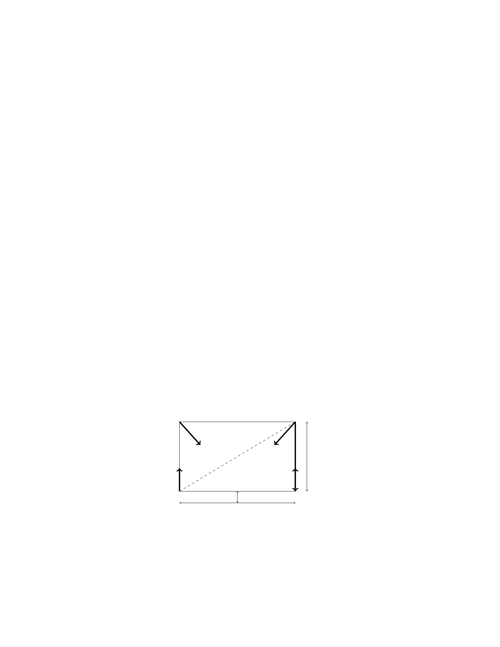
A uniform beam of length Land mass Mis supported by a support at its left
end and by a cable attached two-thirds of the way along the beam. If the beam
makes an angle θwith the horizontal, determine the tension in the cable.
22
Solution
Step 1: Considering the forces acting on the beam, we can identify two main
components: the gravitational force and the tension force from the cable. Let’s
start by drawing a free-body diagram of the beam.
Step 2: The gravitational force acting on the beam can be broken down into
two components: one parallel to the beam (M g sin θ) and one perpendicular to
the beam (Mg cos θ).
Step 3: The tension force in the cable can be resolved into components
parallel (Tsin θ) and perpendicular (Tcos θ) to the beam.
Step 4: In the vertical direction, the sum of the forces must be zero for the
beam to be in equilibrium. Therefore, we have the following equation:
Tcos θ=Mg cos θ
Step 5: Solving for the tension Tgives:
T=Mg
Step 6: Therefore, the tension in the cable supporting the beam is equal to
the gravitational force acting on the beam, which is Mg.
Question 28
Question
A uniform horizontal beam of length Land weight Wis attached to a vertical
wall by a hinge at one end and holds a weight wat the other end. The beam
makes an angle θwith the vertical. Find an expression for the magnitude of the
force exerted by the hinge on the beam in terms of L,θ,W, and w.
Solution
Step 1: Draw a free-body diagram for the beam.
WFhinge
wN
Ffriction
L
Lsin θ
Lcos θ
Step 2: Write the equations of equilibrium in the xand ydirections. In the
xdirection: XFx= 0 =⇒Fhinge −wsin θ= 0
23

In the ydirection:
XFy= 0 =⇒N−W+wcos θ= 0
Step 3: Solve the equations to find the magnitude of the force exerted by
the hinge on the beam, Fhinge. From the first equation:
Fhinge =wsin θ
Question 29
Question
A uniform meter stick of mass 0.20 kg is supported horizontally at its end by
two strings, each of which is at an angle of 30 degrees with the stick. One string
has a tension of 6.0 N. What is the tension in the other string?
Solution
Step 1: We will start by drawing a free-body diagram of the meter stick. Let
the tension in the first string be T1= 6.0 N and the tension in the second string
be T2. The weight of the meter stick acts downwards at its center (0.50 m) with
a magnitude of mg = 0.20 kg ×9.8 m/s2.
Step 2: The net force in the horizontal direction must be zero for equilibrium.
Therefore, the horizontal components of the tensions in the strings must balance
the horizontal component of the weight. So, T1cos 30◦+T2cos 30◦= 0.
Step 3: The net force in the vertical direction must also be zero for equi-
librium. Therefore, the vertical components of the tensions in the strings must
balance the vertical component of the weight. So, T1sin 30◦+T2sin 30◦=mg.
Step 4: Substituting the given values into the equations, we get:
6.0 cos 30◦+T2cos 30◦= 0
6.0 sin 30◦+T2sin 30◦= 0.20 ×9.8
Step 5: Solving these two equations simultaneously, we find that T2= 9.0 N.
Therefore, the tension in the other string is 9.0 N.
Question 30
Question
A steel cable with a length of 10 m and a diameter of 2 cm is hung vertically
from a support. If the Young’s modulus for steel is 2 ×10¹¹ N/m2, calculate the
elongation of the cable due to its own weight. The density of steel is 7.8×10³
kg/m3.
24

Solution
Step 1: First, calculate the mass of the cable. Given: Density of steel, ρ=
7.8×10³kg/m3= 7.8×10⁻³g/cm3
Diameter of the cable, d= 2 cm = 2 ×10⁻²m
Length of the cable, L= 10 m
The volume of the cable can be calculated using the formula for the volume
of a cylinder:
V=πr2h
where ris the radius and is half of the diameter: r=d
2, and h=L. Thus, the
volume Vof the cable is given by:
V=πd
22
L=π2×10⁻²
22
×10 = π×10−4×10 = π×10−3m3
The mass mof the cable can be calculated using the formula:
m=ρV
Substitute the values of ρand V:
m= 7.8×10³×π×10−3= 7.8×π×100= 7.8πkg
Step 2: Calculate the weight of the cable. The weight Wof the cable is
given by:
W=mg
where gis the acceleration due to gravity. Substitute the values of mand g:
W= 7.8π×9.8 N = 76.44πN
Step 3: Calculate the stress in the cable. The cross-sectional area Aof the
cable can be calculated using the formula for the area of a circle:
A=πr2
Substitute the value of r:
A=πd
22
=π2×10⁻²
22
=π×10−4m2
The stress σin the cable is given by:
σ=F
A
where Fis the force acting on the cable (weight Win this case). Substitute the
values of Wand A:
σ=76.44π
π×10−4=76.44
10−4= 764400 N/m2
25
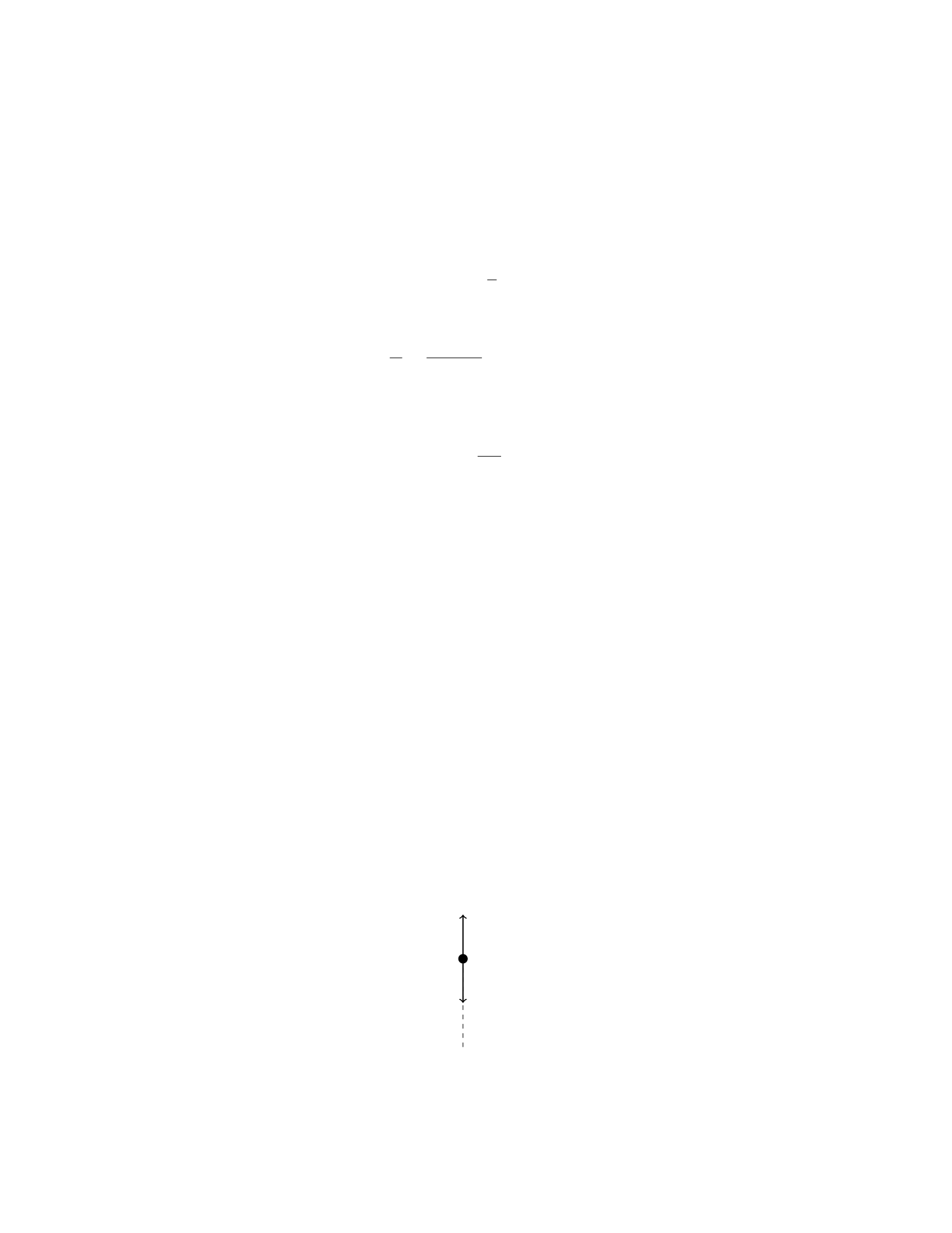
Step 4: Calculate the strain in the cable. The strain εis defined as the ratio
of the change in length ∆Lto the original length L. The Young’s modulus Y
is related to stress and strain by the formula:
Y=σ
ε
Therefore, the strain εcan be expressed as:
ε=σ
Y=764400
2×1011 = 3.822 ×10⁻⁶
Step 5: Calculate the elongation of the cable. The elongation ∆Lof the
cable can be calculated using the formula for strain:
ε=∆L
L
Solving for ∆L:
∆L=ε×L= 3.822 ×10−6×10 = 3.822 ×10⁻⁵m
Therefore, the elongation of the cable due to its own weight is 3.822×
Question 31
Question
A uniform rod of length Land mass Mis hanging vertically from one end, with
the other end fixed. A mass mis attached to the free end of the rod. If the rod
is in equilibrium, determine the tension at the fixed end in terms of L,M,m,
and the acceleration due to gravity, g.
Solution
Let’s consider the forces acting on the rod in equilibrium. There are three forces
acting on the rod: the tension at the fixed end, the weight of the rod, and the
weight of the mass m.
Step 1: Free Body Diagram
First, let’s draw a free body diagram of the rod:
T
Mg
mg
26

Step 2: Write the Equations of Equilibrium
In the vertical direction, the forces must balance out for the rod to be in equi-
librium. Therefore, we have:
T=Mg +mg
Step 3: Using the Given Information
We know that the total length of the rod is L, so the distance from the fixed
end to the center of mass of the rod is L/2. The weight of the rod acts at its
center of mass. The weight of the rod is M g, and it acts at a distance of L/2
from the fixed end. Thus, the torque due to the weight of the rod is
Mg ·L
2
The mass mis attached at the end of the rod, so its weight mg acts at the
end of the rod which is at a distance Lfrom the fixed end. The torque due to
the weight of mass mis
mg ·L
Step 4: Write the Torque Equation
In equilibrium, the net torque about the fixed end of the rod is zero. Therefore,
the torque due to the weight of the rod equals the torque due to the weight of
mass m:
Mg ·L
2=mg ·L
Step 5: Solve for T
Substitute the given relationship for Tinto the torque equilibrium equation:
T=Mg +mg =mg ·L
L
2
= 2mg
Therefore, the tension at the fixed end is 2mg.
Question 32
Question
A rod of length Land uniform density ρis pivoted at one end and held horizon-
tally. A force Fis applied at a distance dfrom the pivot perpendicular to the
rod, causing it to rotate about the pivot. Calculate the angular acceleration of
the rod in terms of the given parameters.
Solution
Step 1: The torque about the pivot point due to the force Fis given by τ=F·d.
Step 2: The moment of inertia of the rod about the pivot point is I=1
3ML2
where M=ρAL and Ais the cross-sectional area of the rod.
27

Step 3: The torque due to the force is also equal to the moment of inertia
times the angular acceleration, τ=I·α.
Step 4: Substituting in the expressions for torque and moment of inertia, we
have F·d=1
3ρALL2α.
Step 5: Solving for the angular acceleration α, we get α=3F
ρAL ·1
L=3F
ρA .
Therefore, the angular acceleration of the rod is α=3F
ρA .
Question 33
Question
A uniform ladder of length Land mass mrests against a smooth vertical wall.
The ladder makes an angle θwith the ground. Find the normal forces exerted
by the wall and the ground on the ladder.
Solution
Step 1: Draw a free body diagram for the ladder. The forces acting on the ladder
are the weight mg, the normal force N1from the wall, and the normal force N2
from the ground. Step 2: Resolve the weight mg into components parallel
and perpendicular to the ladder. The parallel component is mg sin(θ) and the
perpendicular component is mg cos(θ). Step 3: Write down the equations of
equilibrium for the ladder:
XFx=0:N1=mg sin(θ)
XFy=0:N2=mg cos(θ)
Therefore, the normal force exerted by the wall on the ladder is N1=mg sin(θ)
and the normal force exerted by the ground on the ladder is N2=mg cos(θ).
Question 34
Question
A uniform steel beam of length L= 8.00 m is to be supported by two cables
attached at the ends of the beam. If the beam has a mass of 500 kg, determine
the tension in each cable when a 2000 kg mass is suspended at the middle of
the beam. Assume the beam weighs 10 N per meter.
Solution
Step 1: Draw a free-body diagram for the steel beam and the masses. Let T1
and T2be the tensions in the cables at each end of the steel beam.
28
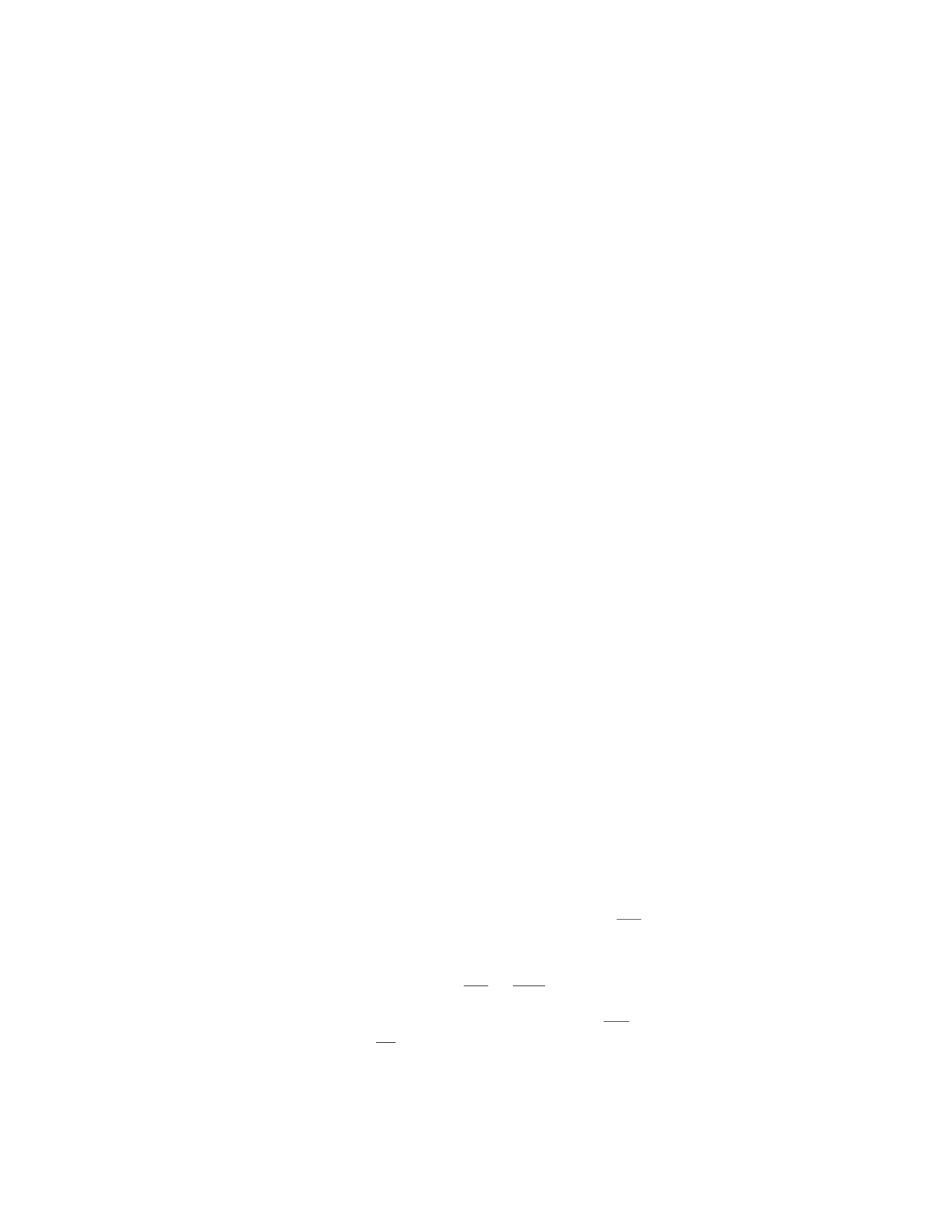
Step 2: Write the equation for the sum of the forces in the vertical direction.
The beam is in equilibrium, so the sum of the forces in the vertical direction
must be zero.
The forces acting vertically are: - The weight of the beam: Wbeam =mg =
(500 kg ×9.8 m/s2) N = 4900 N - The weight of the attached mass: Wmass =
mg = (2000 kg ×9.8 m/s2) N = 19600 N - The tension in cable 1 (T1) acting
upwards - The tension in cable 2 (T2) acting upwards
Now, we can write the equation for the sum of forces in the vertical direction:
T1+T2−Wbeam −Wmass = 0
Step 3: Find the weight of the beam. The weight of the beam is given as 10 N
per meter and the length of the beam is 8.00 m. Wbeam = (10 N/m ×8.00 m) =
80 N
Step 4: Substitute the values into the equation. T1+T2−4900 N−19600 N =
0
Step 5: Solve for T1and T2. Since the mass is located at the middle of the
beam, the beam is balanced and T1=T2.
2T−24500 N = 0 2T= 24500 N T= 12250 N
Therefore, the tension in each cable is 12250 N.
Question 35
Question
A uniform rod of length Land mass Mis supported at its ends by two vertical
strings. A weight Wis placed at a distance xfrom one end of the rod, where
0< x < L. The tension in the left string is twice that in the right string. Find
the tensions in the two strings.
Solution
Step 1: Draw a free body diagram of the rod. Let TLbe the tension in the left
string and TRbe the tension in the right string.
Step 2: Set up the equilibrium equations in the vertical direction:
(TL+TR=Mg
TL= 2TR
Step 3: Substitute TL= 2TRinto the first equation:
2TR+TR=Mg =⇒3TR=M g =⇒TR=Mg
3
Step 4: Now, find TLusing TL= 2TR:
TL= 2 ·Mg
3=2Mg
3
Step 5: Therefore, the tension in the left string TL=2Mg
3and the tension
in the right string TR=Mg
3.
29

Nf+Mg sin(θ)−Mg cos(θ)=0
Step 6: Solve for Nfto obtain the expression for the normal force exerted
by the floor on the ladder:
Nf=Mg(cos(θ)−sin(θ))
Question 2
Question
A uniform beam of length Land mass Mis supported by two cables, one at
each end. The tension in the left cable is twice the tension in the right cable.
If the beam is in equilibrium and the cables make angles of θand ϕwith the
horizontal, respectively, determine the masses of the cables.
Solution
Step 1: We analyze the forces acting on the beam. Let TLbe the tension in
the left cable and TRbe the tension in the right cable. The forces acting on
the beam in the vertical direction are: - The weight of the beam Mg acting
downward. - The vertical components of the tension in the left and right cables,
which are TLcos θand TRcos ϕrespectively.
Since the beam is in equilibrium, the sum of the vertical forces must be zero:
TLcos θ+TRcos ϕ=Mg (1)
Step 2: Next, we analyze the torque about the left end of the beam. The
torque due to the weight of the beam is zero since it acts at the center of the
beam. The torques due to the tensions in the cables are: - The torque due to
the tension in the left cable is TLsin θ·L
2, which produces a counterclockwise
torque. - The torque due to the tension in the right cable is TRsin ϕ·L
2, which
produces a clockwise torque.
For rotational equilibrium, the sum of the torques must be zero:
TLsin θ·L
2=TRsin ϕ·L
2(2)
Step 3: Now we use the fact from the problem that TL= 2TR:
2TRcos θ+TRcos ϕ=Mg (3)
2TRsin θ=TRsin ϕ(4)
Step 4: Solving equations (3) and (4) simultaneously, we find:
2 sin θcos θ= sin ϕcos ϕ
2 sin 2θ= sin 2ϕ
Step 5: The masses of the cables can be found by using the relationships
ML=TL
gand MR=TR
g, where gis the acceleration due to gravity.
2

Question 3
Question
A uniform wooden beam of length Land mass Mis supported horizontally by
a hinge at one end and by a vertical rope at the other end. The beam makes
an angle θwith the horizontal. Find the tension in the rope.
Solution
Step 1: We begin by drawing a free body diagram of the beam. There are three
forces acting on the beam: the weight Mg acting at the center of mass, the
normal force Nacting at the hinge, and the tension Tacting at the rope. The
beam makes an angle θwith the horizontal.
Step 2: We can write out the force equations in the xand ydirections. In
the xdirection, the net force is zero (Fx= 0), and in the ydirection, the net
force is zero (Fy= 0). The equations are:
ΣFx=−Nsin θ= 0
ΣFy=Ncos θ−Mg −T= 0
Step 3: From the first equation, we find that N= 0 or sin θ= 0. Since the
beam is not in free fall, we have N= 0, so sin θ= 0 and θ= 0◦.
Step 4: Substituting θ= 0◦into the second equation, we find:
Ncos 0 −Mg −T= 0
Simplifying, we get:
N−Mg −T= 0
Step 5: Solving for the tension T, we have:
T=N−Mg
Step 6: Since N=Mg, we get:
T= 0
Therefore, the tension in the rope is zero.
Question 4
Question
A 2 kg box sits on a horizontal tabletop. The coefficient of static friction between
the box and the table is 0.6. A horizontal force of 12 N is applied to the box.
Find the magnitude of the smallest additional force that must be applied to the
box in order to make it move.
Solution
Step 1: Draw a free-body diagram of the box. Step 2: Identify the forces acting
on the box. These include the gravitational force (mg), the normal force (N),
the horizontal applied force (Fapplied), and the force of static friction (fs). Step
3: Write the equilibrium equation in the horizontal direction. The equation
3

is PFx= 0. Step 4: In the horizontal direction, the forces acting are the
applied force (Fapplied) to the right, and the force of static friction (fs) to the
left. So we have Fapplied −fs= 0. Step 5: The force of static friction can be
calculated using the equation fs=µsN. Given that µs= 0.6 and N=mg, we
have fs= 0.6mg. Step 6: Substitute the expression for fsinto the equilibrium
equation and solve for the minimum applied force needed to overcome static
friction. We get Fapplied = 0.6mg = 0.6(2)(9.8) = 11.76 N. Therefore, the
magnitude of the smallest additional force that must be applied to the box in
order to make it move is 0.24 N.
Question 5
Question
A cylindrical steel rod of length 2.0 m and diameter 2.0 cm is hung vertically
from the ceiling. The Young’s modulus for steel is 2.0×10¹¹ N/m2. If the
rod stretches by 0.50 mm under its own weight, what is the mass of the rod?
(Assume the rod is a uniform solid cylinder and neglect any effects of air resis-
tance.)
Solution
Step 1: Determine the cross-sectional area of the steel rod. The cross-sectional
area of a cylinder can be calculated using the formula:
A=πr2
Given that the diameter of the rod is 2.0 cm, the radius rcan be calculated as:
r=2.0 cm
2= 1.0 cm = 0.01 m
Thus, the cross-sectional area is:
A=π(0.01 m)2= 3.14 ×10⁻⁴m2
Step 2: Calculate the weight of the rod using the force equation. The weight
mg of the rod is equivalent to the force causing it to stretch. This force is given
by Hooke’s Law:
F=k∆L
where kis the spring constant (Young’s modulus) and ∆Lis the change in
length. Using this equation:
F=A·k·L
L0
4
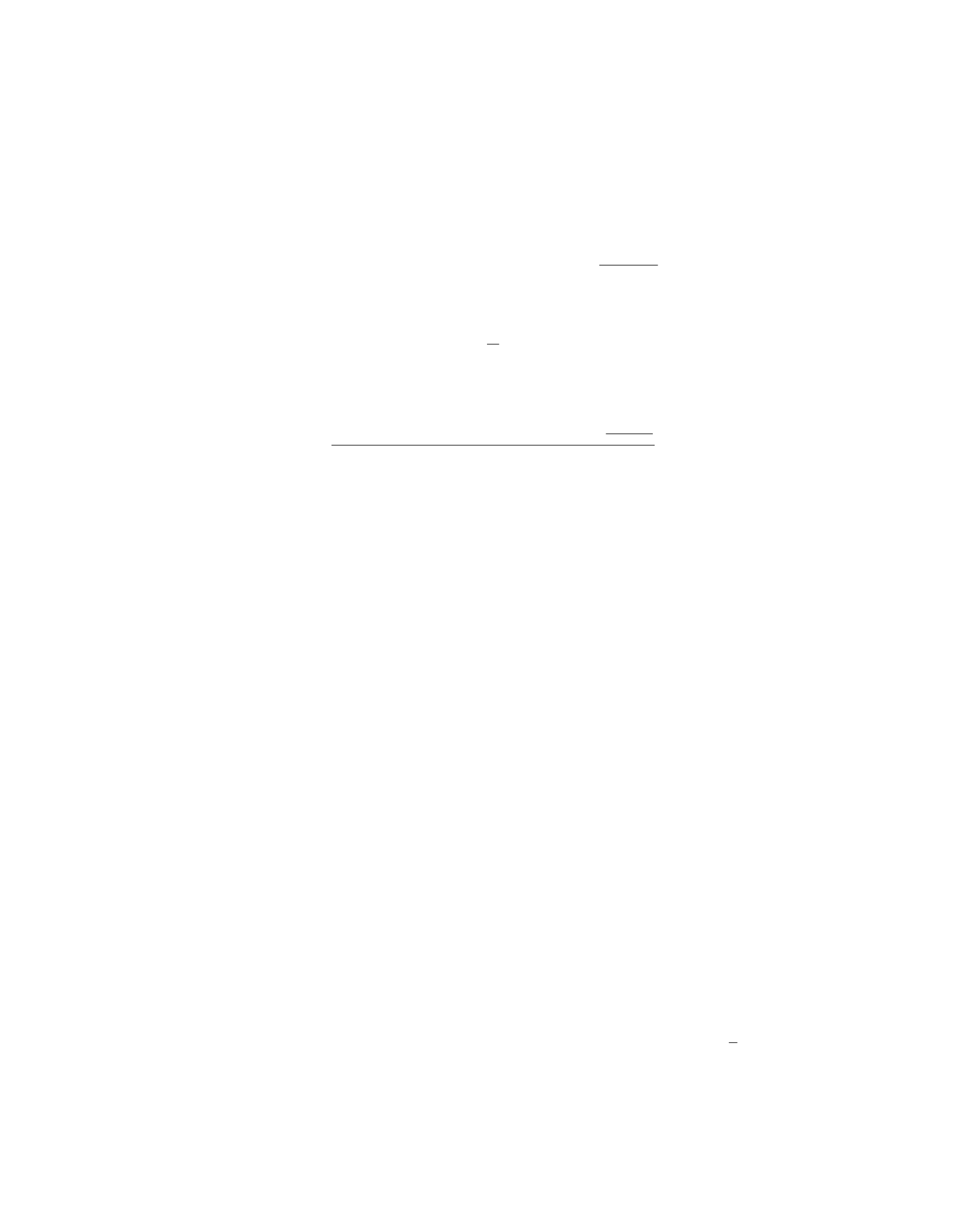
Given that L= 0.50 mm = 0.0005 m, and the Young’s modulus k= 2.0×10¹¹
N/m2, the force can be calculated as:
F= (3.14 ×10⁻⁴m2)×(2.0×1011 N/m2)×0.0005 m
2.0 m
Step 3: Calculate the mass of the rod using the weight. Since F=mg, we
can solve for the mass m:
m=F
g
where g= 9.81 m/s2is the acceleration due to gravity. Substituting the value
of Finto the equation:
m=(3.14 ×10⁻⁴m2)×(2.0×1011 N/m2)×0.0005 m
2.0 m
9.81 m/s2
Therefore, the mass of the rod is calculated as shown above.
Question 6
Question
A uniform beam of length Land mass Mis supported by a vertical cable
attached to one end of the beam. The other end of the beam is in contact with
a frictionless wall. The cable makes an angle θwith the beam. Find the tension
in the cable.
Solution
Step 1: First, draw a free-body diagram of the beam. Label all the forces acting
on the beam. There are three forces acting on the beam: the gravitational
force Mg acting downward at the center of mass, the normal force Nacting
perpendicular to the wall at the point of contact, and the tension Tacting in
the direction of the cable. The angle between the beam and the horizontal is
also θ.
Step 2: Break down the gravitational force Mg into components parallel and
perpendicular to the beam. The component parallel to the beam is Fparallel =
Mg sin(θ), and the component perpendicular to the beam is Fperpendicular =
Mg cos(θ).
Step 3: The beam is in equilibrium, so the sum of the forces in the vertical
direction is zero. This gives us the equation:
Tcos(θ) = Mg cos(θ)
Step 4: The beam is also in rotational equilibrium about the point of contact
with the wall. The torque due to the tension Tmust balance the torque due to
the gravitational force. The torque due to the gravitational force is Fparallel ·L
2,
5
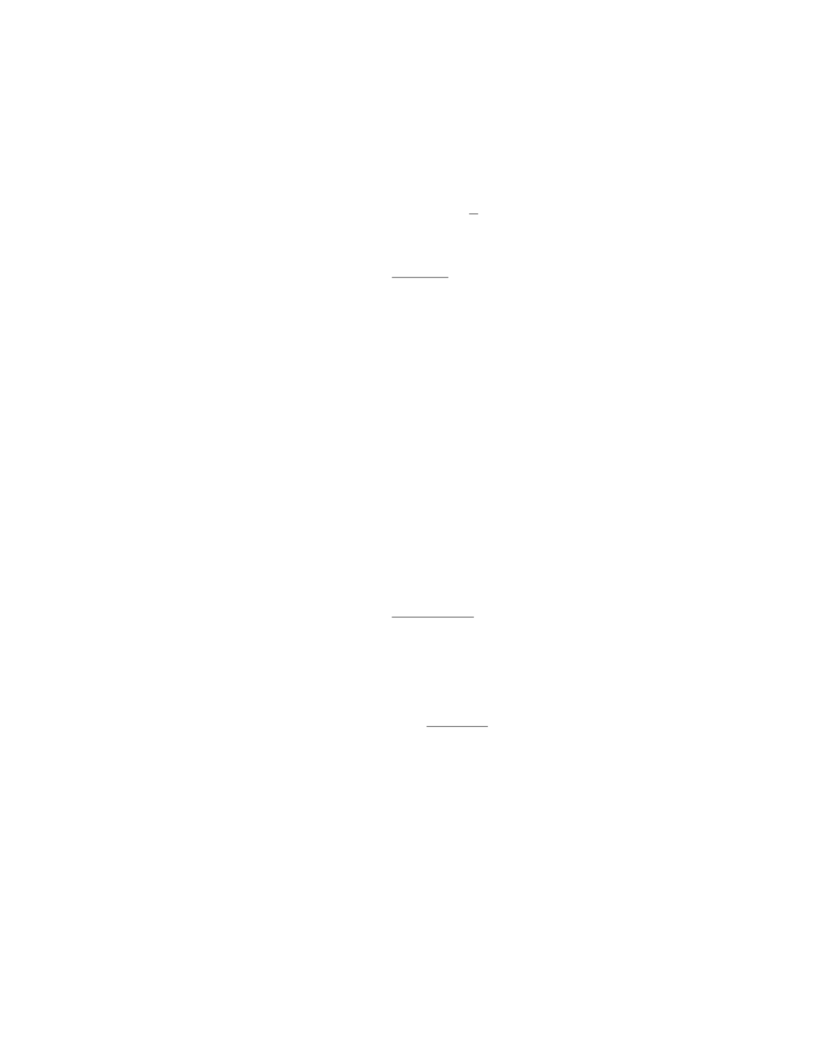
and the torque due to the tension is Tsin(θ)·L. Setting these torques equal
gives us:
Tsin(θ)·L=Fparallel ·L
2
Step 5: Substituting the expression for Fparallel into the torque equation and
solving for T, we get:
T=Mg sin(θ)
2 cos(θ)
Question 7
Question
A uniform meterstick of mass 0.20 kg is supported horizontally by a string
attached at the 10 cm mark. A weight of 0.50 N hangs from the end of the stick
at the 100 cm mark. What is the tension in the string and the force exerted on
the stick at the fulcrum?
Solution
Step 1: Find the tension in the string using the torque equation. Let’s define the
clockwise torque as positive. The torques due to the weight of the meterstick
and the weight hanging from the end must balance each other out to maintain
equilibrium. The torque equation is:
Tstring ·0.10 m = 0.50 N ·1.00 m
Solving for the tension Tstring:
Tstring =0.50 N ·1.00 m
0.10 m
Step 2: Calculate the force exerted on the stick at the fulcrum. Since the
stick is in equilibrium, the sum of all forces in the vertical direction must be
zero. Let Ffulcrum be the force exerted on the stick at the fulcrum.
Ffulcrum = 0.20 kg ·9.81 m/s2−0.50 N
Therefore, the tension in the string is 0.50 N·1.00 m
0.10 m = 5.00 N, and the force
exerted on the stick at the fulcrum is 0.20 kg ·9.81 m/s2−0.50 N = 1.82 N.
Question 8
Question
A uniform rod of length Land mass Mis suspended horizontally from one end.
Two forces, each of magnitude F, are applied at points 2L/3 and 5L/6 from the
end where the rod is suspended. Determine the tension in the rod at the point
of suspension.
6

Solution
Step 1: To find the tension at the point of suspension, we need to consider the
net torque acting on the rod about that point to ensure equilibrium.
Step 2: Let Tbe the tension at the point of suspension. The forces Fapplied
at 2L/3 and 5L/6 create a torque about the suspension point in the clockwise
direction. Using the lever arm D:
D=L
6and D′=L
2.
Step 3: The torque due to the force Fat 2L/3 is −F·L
6(since it is trying
to rotate counterclockwise).
Step 4: The torque due to the force Fat 5L/6 is −F·L
2(also trying to
rotate counterclockwise).
Step 5: For equilibrium, the net torque about the suspension point must be
zero:
0 = −F·L
6−F·L
2+T·L.
Step 6: Solving the equation above for Tgives:
T=F
2.
Step 7: Therefore, the tension at the point of suspension is half of the force
applied (T=F
2).
Question 9
Question
A thin rod of length Land mass Mis hanging vertically from a fixed point. A
block of mass mis attached to the bottom end of the rod. The rod remains in
equilibrium, making an angle θwith the vertical. Calculate the tension in the
rod and the normal force on the block.
Solution
1. Free body diagram:
Let’s draw the free body diagram for both the rod and the block.
For the rod: - The forces acting on the rod are the tension Tin the rod, the
weight of the rod Mg acting at the center of mass, and the normal force Nat
the fixed point. - The vertical component of tension balances the weight of the
rod and the horizontal component of tension balances the horizontal component
of the normal force.
For the block: - The forces acting on the block are the tension Tin the rod
and the weight of the block mg. - The tension Tacts at an angle θwith the
vertical.
7

2. Equilibrium for the rod:
For the rod to be in equilibrium vertically:
Tcos θ=Mg
For the rod to be in equilibrium horizontally:
Tsin θ=N
3. Equations of equilibrium for the block:
In the vertical direction:
T=mg
4. Solve for Tand N:
From the equation for equilibrium in the vertical direction for the rod:
T=Mg
cos θ
From the equilibrium equation for the block:
T=mg
Substitute the expression for Tin terms of mg into the horizontal equilibrium
equation for the rod:
mg sin θ=N
Therefore, the tension in the rod is T=M g
cos θand the normal force on the
block is N=mg sin θ.
Question 10
Question
A block of mass mis hanging from a vertical spring, causing it to stretch by
a distance xfrom its equilibrium position. The spring constant is kand the
acceleration due to gravity is g. Find the elastic potential energy stored in the
spring due to the block.
Solution
Step 1: The force exerted by gravity on the block is given by Fgravity =mg.
The force exerted by the spring on the block is equal in magnitude but opposite
in direction to the force exerted by gravity, so Fspring =−mg.
Step 2: From Hooke’s Law, the force exerted by a spring is given by Fspring =
−kx, where xis the displacement of the spring from its equilibrium position.
Step 3: Setting Fspring =Fgravity, we have −mg =−kx. Solving for x, we
find that x=mg
k.
8
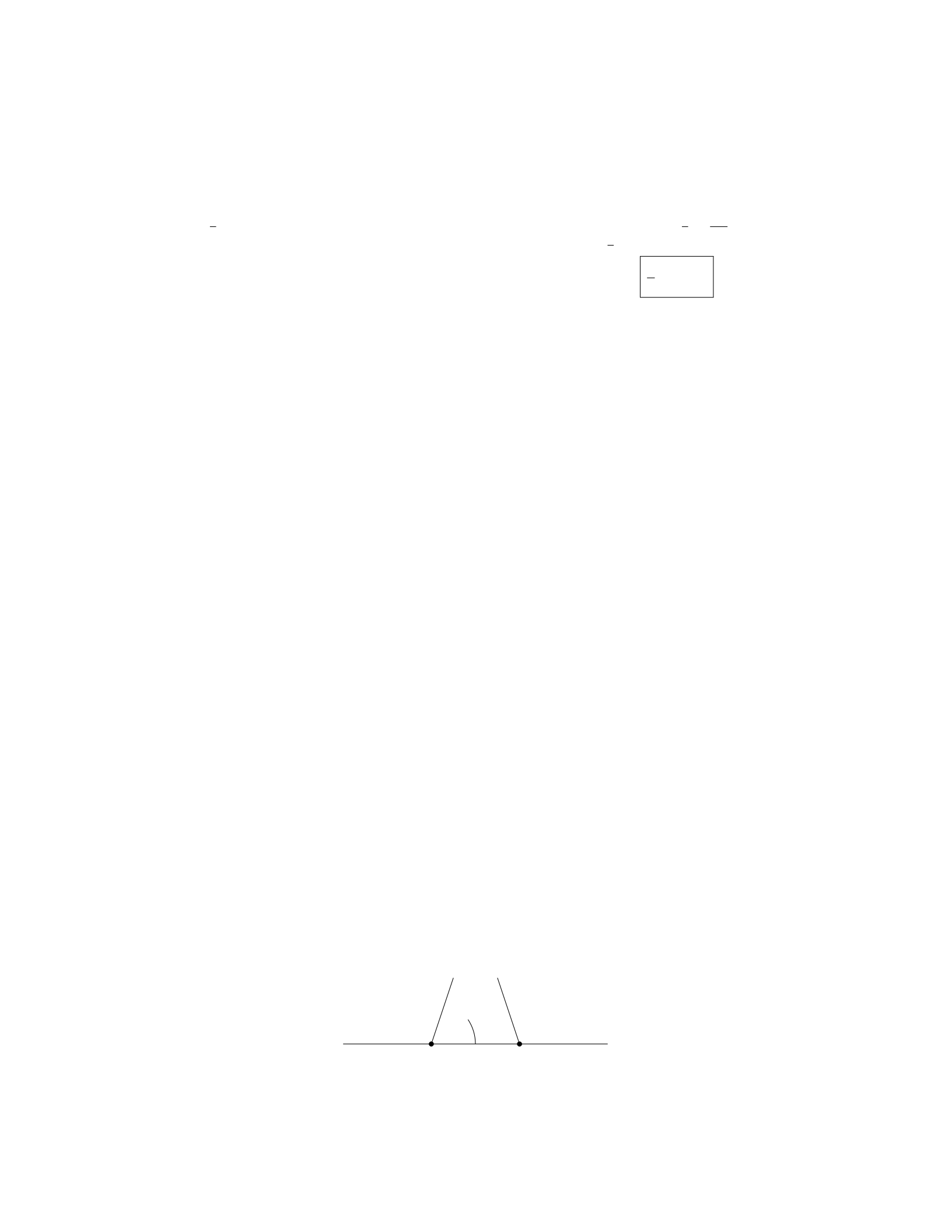
Step 4: The elastic potential energy stored in the spring is given by P Eelastic =
1
2kx2. Substituting the value of xinto this equation, we get P Eelastic =1
2kmg
k2.
Step 5: Simplifying the expression, we have P Eelastic =1
2m2g2/k. Thus, the
elastic potential energy stored in the spring due to the block is 1
2m2g2/k .
Question 11
Question
A uniform beam of length Land mass Mis supported by a hinge at one end
and by a cable that makes an angle θwith the beam at the other end. The cable
exerts a horizontal force Fon the beam. Determine the tension in the cable.
Solution
Step 1: Begin by drawing a free-body diagram of the beam, including all the
forces acting on it. We have gravity (Mg) acting downwards at the center of
mass of the beam, the normal force (N) acting upwards at the hinge, and the
tension in the cable (T) acting at an angle θwith respect to the horizontal.
Step 2: Decompose the tension Tinto vertical and horizontal components. The
horizontal component of Tis Tcos θand the vertical component is Tsin θ. Step
3: Write the equilibrium equations for the beam in both the horizontal and
vertical directions. In the horizontal direction, we have Tcos θ=Fsince the
horizontal forces must balance each other. In the vertical direction, we have
N=Mg +Tsin θsince the vertical forces must also balance. Step 4: To find
the tension T, we need to eliminate Nfrom our equations. We can do this by
expressing Nin terms of M,g, and L, since we are given that the beam has a
length Land mass M. Since the beam is uniform, the center of mass will be
at L/2 from the hinge. Thus, N×L/2 = Mg ×L/2. This gives us N=Mg.
Step 5: Substitute N=Mg back into the equation N=Mg +Tsin θand solve
for T. We get T=M g sin θ. Step 6: Therefore, the tension in the cable is
T=Mg sin θ.
Question 12
Question
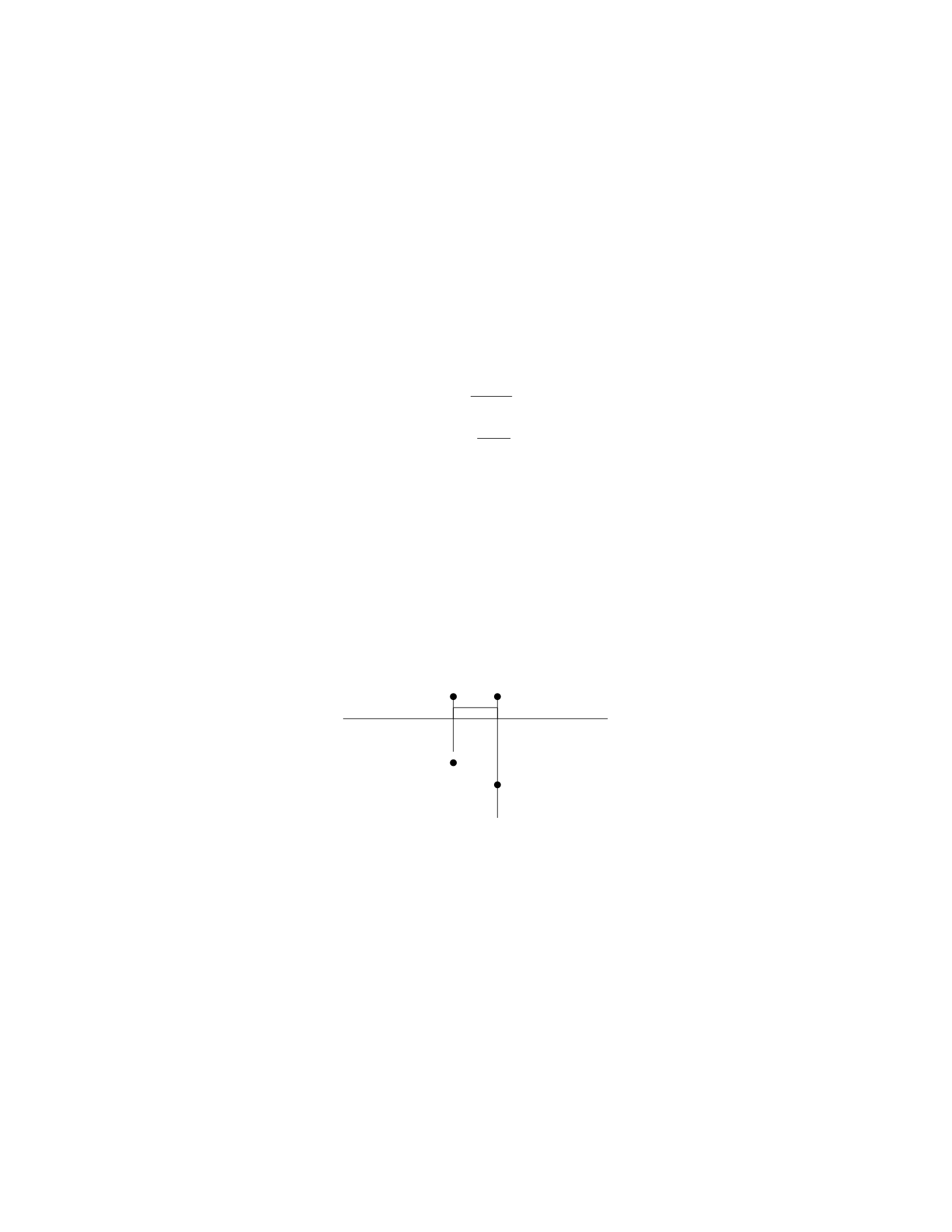
A uniform rod of mass Mand length Lis suspended horizontally at one end by
two vertical strings of length Las shown in the figure. The rod makes an angle
θwith the horizontal. What is the tension Tin each string?
θ
9
Solution
Step 1: Draw forces acting on the rod and write equilibrium equations. Let T
be the tension in each string. The forces acting on the rod are the gravitational
force Mg acting downward at the center of the rod and the tension forces T
acting upwards in the strings. In the vertical direction, the net force must be
zero:
2Tcos θ=Mg
Step 2: Solve for the tension T. Solving for Tin the equation above:
T=Mg
2 cos θ
Therefore, the tension in each string is Mg
2 cos θ.
Question 13
Question
A uniform rod of length Land mass Mis suspended horizontally by two vertical
strings, one attached at the end of the rod and the other attached a distance
dfrom the end (see diagram below). The tension in the string attached at the
end is T1and the tension in the string attached at a distance dfrom the end is
T2. What are the tensions T1and T2in terms of M,L,d, and g(acceleration
due to gravity)?
T1T2
m1
m2
Solution
Let’s denote the tension in the string attached at the end of the rod as T1and
the tension in the string attached at a distance dfrom the end as T2.
Step 1: Set up equilibrium equations
For the vertical direction: The net force in the vertical direction must be
zero in order for the rod to be in equilibrium.
T1+T2=Mg (1)
For the torque equation: In order for the rod to be in equilibrium, the total
torque about any point must be zero. Let’s choose the point where T1is applied
as the pivot point.
10

Torque due to T1: 0
Torque due to T2:T2·Lsin θ2
The torque equilibrium equation is:
T2·Lsin θ2= 0
Since θ2= tan−1d
L
2= tan−12d
L, the torque equation becomes:
T2·L·sin tan−12d
L= 0
T2·2d= 0
T2= 0 (2)
Step 2: Solve for tensions T1and T2
From equation (1) and equation (2), we have:
T1+ 0 = Mg
T1=Mg
Therefore, the tension in the string attached at the end of the rod is T1=Mg
and the tension in the string attached at a distance dfrom the end is T2= 0.
Question 14
Question
A uniform beam of length Land mass Mis supported by a pivot at one end
and a rope at a distance dfrom the pivot. The beam makes an angle θwith
the horizontal. If the tension in the rope is T, what is the force exerted by the
pivot on the beam?
Solution
1. We will start by drawing a free-body diagram of the beam. The forces acting
on the beam are the force of gravity Mg acting at the center of mass, the tension
Tin the rope, and the force Fpivot exerted by the pivot.
2. Since the beam is in rotational equilibrium, the sum of the torques acting
on it must be zero. Taking the pivot point as the axis of rotation, the torque
due to the force of gravity is L
2Mg sin θ, the torque due to the tension is dT sin θ,
and the torque due to the pivot force is zero.
3. Setting the sum of the torques equal to zero, we have:
L
2Mg sin θ−dT sin θ= 0
4. Solving for the pivot force Fpivot, we have:
Fpivot =L
2Mg −dT
5. Now, we need to find an expression for the tension Tin the rope. This
can be done by considering the equilibrium of the forces in the vertical direction:
11
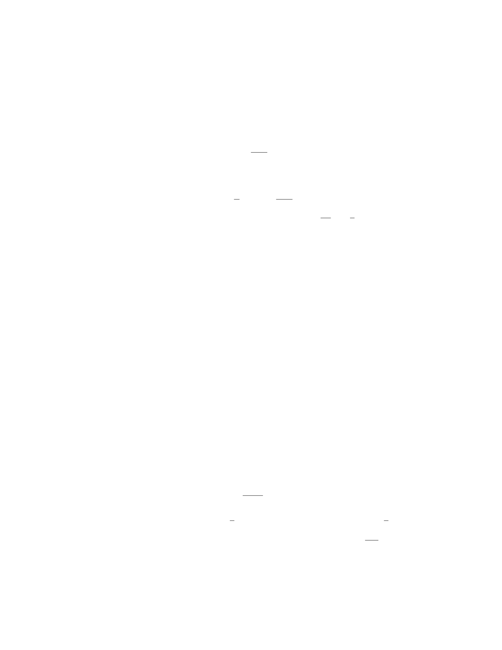
Tcos θ=Mg
6. Solving for T, we get:
T=Mg
cos θ
7. Substituting this expression for Tinto the equation for the pivot force,
we have:
Fpivot =L
2Mg −dMg
cos θ
8. Thus, the force exerted by the pivot on the beam is M g
2(2 −d
Lsec θ).
Question 15
Question
A uniform rod of length Land mass Mis suspended vertically from a hinge
attached to the ceiling. A horizontal force Fis applied at one end of the rod
causing the rod to rotate slightly. Determine the magnitude and direction of
the force Fneeded to maintain equilibrium.
Solution
Let’s denote the distance from the hinge to the center of mass of the rod as
x, and the angle that the rod makes with the vertical as θ. The gravitational
force acting on the rod is M g acting at the center of mass. The force Facts
horizontally at one end of the rod. In order to maintain equilibrium, the torque
due to Fmust balance the torque due to gravity.
Step 1: Find the torque due to the gravitational force. The torque due to
the gravitational force about the hinge is given by τgravity =x(Mg) sin θ.
Step 2: Find the torque due to the force F. The torque due to the force F
is τF=F(L−x) sin θ.
Step 3: Set up the condition for rotational equilibrium. For rotational
equilibrium, the sum of torques must be zero. Thus, we have:
τgravity =τF
x(Mg) sin θ=F(L−x) sin θ
Solving for F, we get:
F=x
L−xMg
Step 4: Analyze the direction of the force F. The direction of the force F
depends on the value of x. If x < L
2, then Fpoints towards the hinge. If x > L
2,
then Fpoints away from the hinge.
Thus, the magnitude of the force Fneeded to maintain equilibrium is x
L−xMg,
and the direction depends on the value of x.
12

Question 16
Question
A rod of length L, cross-sectional area A, and Young’s modulus Yis suspended
vertically from one end. A force Fis applied horizontally at the other end. Find
the extension of the rod.
Solution
Step 1: Begin by drawing a free-body diagram of the rod. The weight of the
rod acts downward at the midpoint, the force Facts horizontally at the other
end, and the tension Tacts upward at the point where the rod is suspended.
Step 2: Using equilibrium conditions, set the sum of forces in the horizontal
direction to zero. The only horizontal force is the applied force F. Thus, F= 0.
Step 3: Set the sum of forces in the vertical direction to zero. The vertical
forces are the weight of the rod Wacting downward (which can be split into
two equal forces at the midpoint) and the tension force Tacting upward. The
net vertical force is then T−21
2xAρg = 0, where xis the extension of the
rod and ρis the density of the material.
Step 4: The tension Tcan be expressed as T=A·σ=A·Y·ϵ, where σis
the stress and ϵis the strain. The strain can be expressed as ϵ=x
L.
Step 5: Substitute T=AY ϵ into the equation from Step 3 to get AY x
L=
ρA ·g1
2x.
Step 6: Solve for xto find the extension of the rod. We have x=2ρgL
Y.
Therefore, the extension of the rod under the applied force Fis 2ρgL
Y.
Question 17
Question
A wooden beam of length Land uniform cross-sectional area Ais supported at
one end by a wall and has a weight Wattached at the other end. The beam is
in equilibrium. Calculate the magnitude of the force exerted by the wall on the
beam.
Solution
Step 1: First, we need to draw a free-body diagram of the beam to identify the
forces acting on it.
Step 2: The forces acting on the beam are the weight Wacting downward
at the end of the beam, the force of gravity acting at the center of mass of the
beam, and the force Fexerted by the wall on the beam.
Step 3: Since the beam is in equilibrium, the sum of the forces in the vertical
direction must be zero.
Fwall −W= 0
13

Step 4: We can express the weight Win terms of the mass of the beam m
and the acceleration due to gravity g. The weight is given by W=mg.
Step 5: Since the beam has a uniform cross-sectional area Aand is made of
wood, we can express the mass of the beam in terms of its density ρ, length L,
and cross-sectional area A. The mass is given by m=ρAL.
Step 6: Substituting W=mg and m=ρAL into the equilibrium equation,
we get:
Fwall −ρALg = 0
Step 7: Solving for the force Fwall:
Fwall =ρALg
Therefore, the magnitude of the force exerted by the wall on the beam is
ρALg.
Question 18
Question
A solid block of aluminum, with a volume of 0.05 m3, is submerged in water.
The block is connected to a spring scale and the reading on the scale is 420 N.
The density of aluminum is 2700 kg/m3and the density of water is 1000 kg/m3.
Determine the depth to which the block is submerged in the water.
Solution
Step 1: Find the weight of the aluminum block in air. Given: Density of
aluminum, ρAl = 2700 kg/m3
Volume of aluminum block, VAl = 0.05 m3
Acceleration due to gravity, g= 9.81 m/s2
The weight of the block in air can be found using the formula:
WAl =ρAl ×VAl ×g
Substitute the known values to find WAl:
WAl = 2700 ×0.05 ×9.81 = 1321.5 N
Step 2: Find the buoyant force acting on the block. The buoyant force on
the block is equal to the weight of the water displaced. The weight of the water
displaced can be found using the formula:
Wwater =ρwater ×VAl ×g
Substitute the known values to find Wwater:
Wwater = 1000 ×0.05 ×9.81 = 490.5 N
14
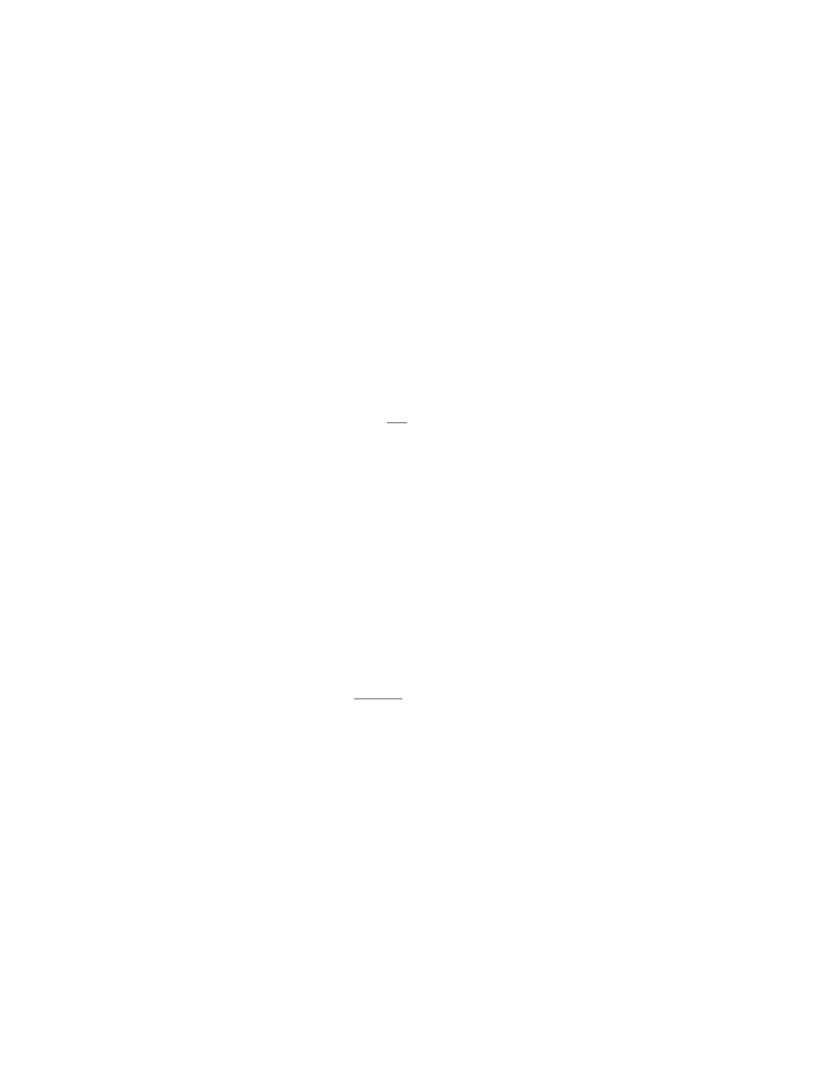
Step 3: Find the net force acting on the block. Since the block is in equilib-
rium, the net force acting on the block is zero. Therefore:
Fnet =WAl −Wwater = 1321.5−490.5 = 831 N
Step 4: Find the depth to which the block is submerged. The spring scale
reading provides the buoyant force acting on the block, which is equal to the
net force. Therefore, the depth to which the block is submerged can be found
using:
Fnet =k×x
where kis the spring constant and xis the displacement of the block.
Given Fnet = 831 N and k= 420 N, solve for x:
831 = 420 ×x
x=831
420 = 1.98 m
Thus, the block is submerged to a depth of 1.98 m in the water.
Question 19
Question
A steel wire of length 2.0 m and diameter 0.50 mm is stretched until its length
increases by 1.0 cm. If the Young’s modulus of steel is 2.0×10¹¹ N/m2, deter-
mine the stress and strain on the wire.
Solution
Step 1: Calculate the original cross-sectional area of the wire. Given that the
wire has a diameter of 0.50 mm, we can calculate the original radius, r0, as
follows:
r0=0.50 mm
2= 0.25 ×10⁻³m
The original cross-sectional area, A0, is given by:
A0=πr2
0
A0=π(0.25 ×10⁻³)2
A0= 1.96 ×10⁻⁷m2
Step 2: Calculate the final length of the wire. Given that the wire’s length
increases by 1.0 cm, the final length, Lf, is:
Lf= 2.0 m + 0.01 m = 2.01 m
15

Step 3: Calculate the strain in the wire. The strain, ϵ, is given by:
ϵ=∆L
L0
ϵ=0.01 m
2.0 m
ϵ= 5 ×10⁻³
Step 4: Calculate the stress in the wire. The stress, σ, is given by Hooke’s
Law:
σ=E·ϵ
σ= 2.0×10¹¹ N/m2×5×10−3
σ= 1.0×10⁹N/m2
Therefore, the stress in the wire is 1.0×10⁹N/m2and the strain is 5 ×10⁻³.
Question 20
Question
A uniform rod of length Land mass Mis held horizontally so that one end is
against a vertical wall. A block of mass mis placed on the other end of the
rod. The coefficient of static friction between the block and the rod is µs. Find
the minimum coefficient of static friction between the wall and the rod that will
prevent the block from slipping.
Solution
1. Draw a free-body diagram of the rod. Consider the forces acting on the rod:
the force of gravity acting on the rod’s center of mass, the normal force from
the wall, and the force of static friction from the wall.
2. Write the torque equation for the rod about its pivot point at the wall.
The torque due to the gravitational force about this point will cause rotation,
so it must be balanced by the torque due to the normal force from the wall and
the static friction force.
3. The torque due to the gravitational force about the pivot point is −MgL
2
(negative because it tries to make the rod rotate clockwise).
4. The torque due to the normal force about the pivot point is zero since
the normal force passes through the pivot point.
5. Let fbe the static friction force between the rod and the wall. The
torque due to this force is +fL (positive because it tries to make the rod rotate
counterclockwise).
6. The torque equation becomes fL =MgL
2.
7. The friction force needed to prevent slipping is given by fmin =µsN,
where Nis the normal force from the wall.
16

8. To find the minimum force of static friction, we need to analyze the
equilibrium of the block. Write equations for the forces in the vertical and
horizontal directions.
9. In the vertical direction, the normal force from the rod balances the force
of gravity acting on the block. So, N=mg.
10. In the horizontal direction, the force of static friction must balance the
force due to the rod’s weight, which is fmin =µsmg.
11. Substitute N=mg into the torque equation: fmin =M gL
2.
12. Therefore, the minimum coefficient of static friction between the wall
and the rod that will prevent the block from slipping is µs=M
2m.
Question 21
Question
A uniform square plate with side length Land mass Mis suspended from a
wire attached to two of its corners. Determine the tension in the wire when the
plate is in equilibrium.
Solution
We can solve this problem using the concept of torque. In equilibrium, the sum
of the torques acting on the plate must be zero.
Step 1: Identify the forces acting on the plate. There are two forces: the
tension in the wire (T) and the gravitational force acting on the center of the
plate.
Step 2: Choose a pivot point. In this case, let’s choose the bottom-left
corner of the plate as the pivot point.
Step 3: Calculate the torque due to the tension in the wire. The torque
(τT) due to the tension in the wire is given by:
τT=T·L
Step 4: Calculate the torque due to the gravitational force. The gravita-
tional force acts on the center of the plate, which is located L
2away from the
pivot point. The torque (τgravity) due to the gravitational force is given by:
τgravity =Mg ·L
2
Step 5: Set up the torque equation. In equilibrium, the sum of the torques
is zero:
τT−τgravity = 0
T·L−Mg ·L
2= 0
17
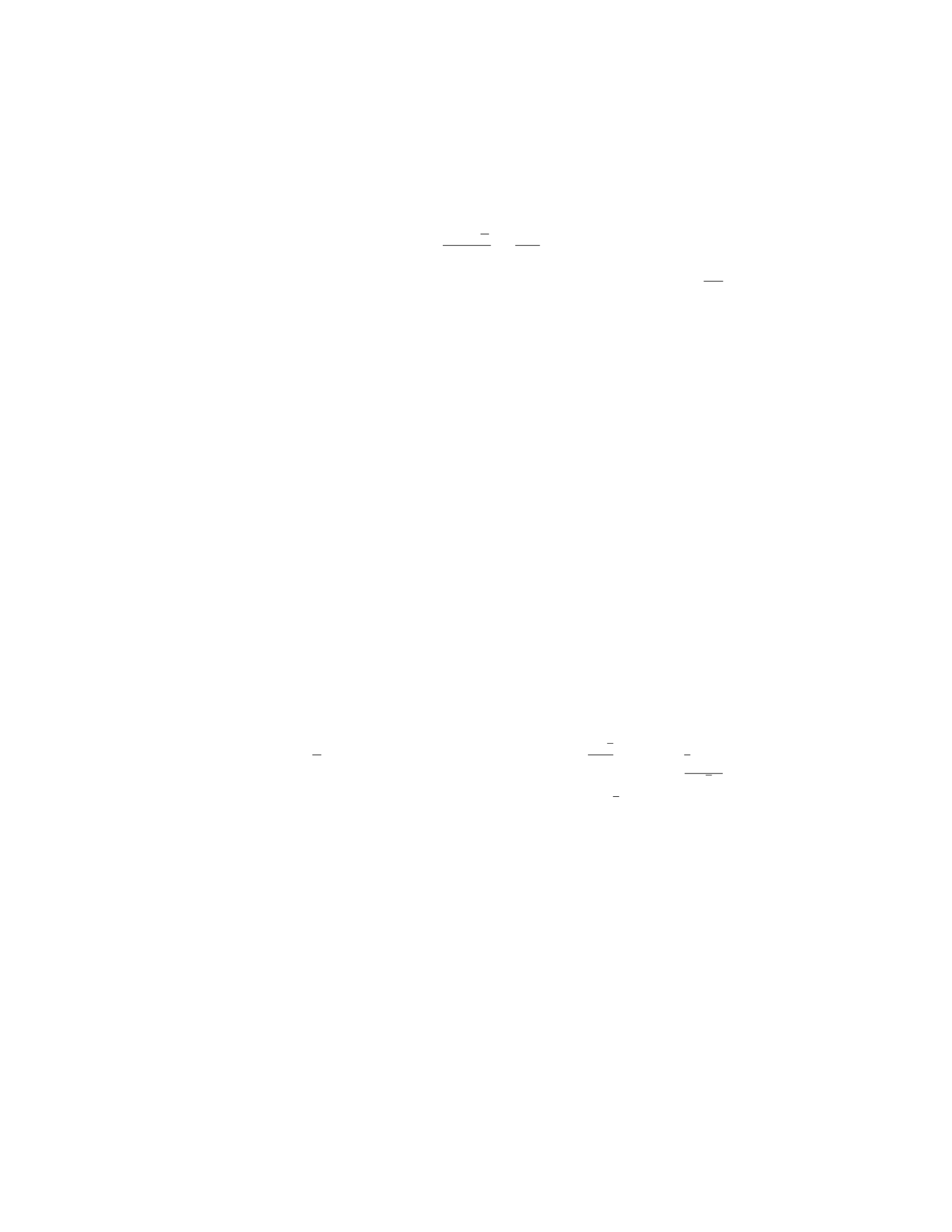
Step 6: Solve for the tension in the wire (T):
T=Mg ·L
2
L=Mg
2
Therefore, the tension in the wire when the plate is in equilibrium is M g
2.
Question 22
Question
A uniform plank of mass 4 kg and length 3 m is positioned at an angle of 30◦
with the horizontal. One end of the plank rests against a smooth vertical wall,
while the other end is supported by a horizontal rope that makes an angle of 60◦
with the horizontal. Find the tension in the rope and the normal force exerted
on the plank by the wall.
Solution
Step 1: Draw the free-body diagram of the plank.
Let Tbe the tension in the rope, Nbe the normal force exerted by the wall, and Wbe the weight of the plank.
Step 2: Resolve the forces into components.
Resolving vertically: N+Tsin 60◦=W(since the plank is not accelerating vertically)
Resolving horizontally: Tcos 60◦=Wsin 30◦(since the plank is not accelerating horizontally)
Step 3: Determine the weight of the plank.
W=mg = 4 ×9.8 = 39.2 N
Step 4: Solve the equations from Step 2 to find Tand N. From the vertical
equation: N+T
2= 39.2 From the horizontal equation: T√3
2= 39.2×1
2= 19.6
Step 5: Solve for Tand N. From the horizontal equation: T=19.6×2
√3≈
22.6 N Substitute Tinto the vertical equation: N+ 22.6×1
2= 39.2
N= 39.2−11.3 = 27.9 N
Therefore, the tension in the rope is approximately 22.6 N and the normal
force exerted by the wall is approximately 27.9 N.
Question 23
Question
A uniform wooden beam of length Land mass Mis lying horizontally on a
frictionless table. A block of mass mis placed at a distance xfrom one end
of the beam. The block is at rest relative to the beam. What fraction of the
beam’s length is the block located (express your answer in terms of L)?
18

Solution
Step 1: Draw a free-body diagram of the wooden beam.
Step 2: The forces acting on the beam are the weight acting downwards at
the center of mass (1
2L) and the normal force (N) acting upwards at the pivot
point.
Step 3: The net torque about the pivot point must be zero for the beam to
be in equilibrium. The torque produced by the block is xmg, and the torque
produced by the weight of the beam is 1
2L·Mg
2. Setting these torques equal
gives us xmg =1
2L·Mg
2.
Step 4: Solve for xin terms of L:x=L
4.
Step 5: The block is located 1
4of the beam’s length away from the end, so
the fraction of the beam’s length where the block is located is 1
4.
Question 24
Question
A long steel wire with a circular cross-section of radius 1.5 mm is attached
between two rigid supports. The wire is under a tension of 500 N. What is the
maximum allowable length the wire can have without breaking? The Young’s
modulus for steel is 2.0×10¹¹ N/m2.
Solution
Step 1: The stress in the wire can be calculated using the formula:
stress = tension
cross-sectional area
The cross-sectional area of the wire can be calculated using the formula for
the area of a circle:
cross-sectional area = πr2
cross-sectional area = π(1.5×10⁻³)2
Substitute the given values:
cross-sectional area = π(1.5×10⁻³)2≈7.07 ×10⁻⁶m2
Step 2: Now, calculate the stress:
stress = 500
7.07 ×10⁻⁶
stress ≈7.07 ×10⁷N/m2
19
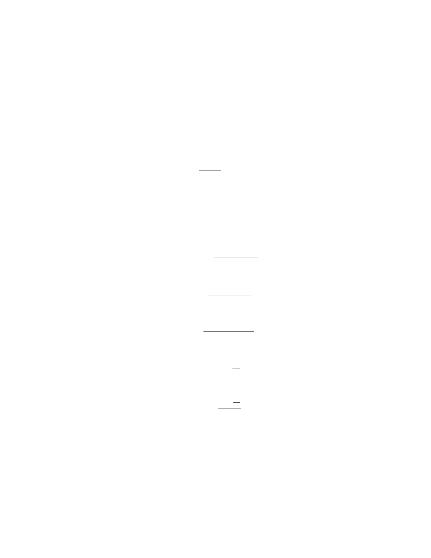
Step 3: The maximum stress a material can handle without breaking is
known as its ultimate tensile strength. For steel, the ultimate tensile strength is
typically around 4 ×10⁸N/m2.
Given that the ultimate tensile strength is 4×10⁸N/m2and the safety factor
is 2 (typical for steel), we can calculate the maximum allowable stress:
max stress = ultimate tensile strength
safety factor
max stress = 4×10⁸
2= 2 ×10⁸N/m2
Step 4: Now, we can calculate the maximum allowable length the wire can
have without breaking using Hooke’s Law:
stress = Y·strain
length
Since the material will break when the stress reaches the maximum allowable
stress, we can rewrite the formula as:
max stress = Y·max strain
length
Rearranging for length:
length = Y·max strain
max stress
Step 5: The strain can be calculated using the formula:
strain = change in length
original length
The change in length is the maximum length the wire can have, so:
max strain = L
L0
Substitute the known values and solve for the maximum allowable length:
length = Y×L
L0
2×10⁸
Given that Y= 2.0×10¹¹ N/m2,L0is the original length of the wire, and
the maximum allowable stress has been calculated. We just need to find the
original length, L0.
20

Question 25
Question
A uniform beam of length Land mass Mis supported by a pivot at one end,
while a block of mass mis hung from the other end. If the beam makes an angle
θwith the horizontal, determine the tension in the cable holding the block in
terms of m,M,L,g, and θ.
Solution
Step 1: Draw a free-body diagram of the beam.
Step 2: Since the beam is in equilibrium, the sum of forces in the vertical
direction is zero. The forces acting in the vertical direction are the tension T
and the force due to gravity acting at the center of mass of the beam.
Step 3: The force due to gravity acting on the beam is equivalent to the
weight of the beam acting through its center of mass, which is at a distance L/2
from the pivot. The weight of the beam is M g, where gis the acceleration due
to gravity.
Step 4: Using trigonometry, the vertical component of the weight of the
beam is Mg cos(θ), and the horizontal component is Mg sin(θ).
Step 5: The torque about the pivot due to the weight of the beam is given
by τbeam = (M g cos(θ))(L/2). This torque must be balanced by the torque due
to the tension in the cable, which is T(L).
Step 6: Setting up the torque equilibrium equation:
T(L) = MgL
2cos(θ)
Step 7: Thus, the tension in the cable holding the block is:
T=Mg
2cos(θ)
Question 26
Question
A uniform solid cylinder of mass Mand radius Rrolls without slipping down
an inclined plane as shown in the figure. The cylinder starts from rest at a
height habove the bottom of the incline. The incline makes an angle θwith the
horizontal, and the coefficient of kinetic friction between the cylinder and the
incline is µk. Determine the acceleration of the center of mass of the cylinder.
solid_cylinder.png
21

Solution
Step 1: Draw a free body diagram for the cylinder. The forces acting on the
cylinder are its weight W=Mg downward, the normal force Nperpendicular
to the incline, and the frictional force fkparallel to the incline.
Step 2: Break down the weight Winto components perpendicular (W⊥) and
parallel (W||) to the incline. The weight component parallel to the incline will
provide the force driving the cylinder down the incline.
Step 3: The net force acting on the cylinder is the component of the weight
down the incline (W||) minus the frictional force fk:
Fnet =W|| −fk
Step 4: The force acting down the incline is given by
W|| =Wsin θ
Step 5: The frictional force fkcan be calculated using the coefficient of
kinetic friction µk:
fk=µkN
Step 6: The normal force Ncan be calculated by considering the forces
perpendicular to the incline:
N=W⊥=Wcos θ
Step 7: Substitute the expressions for W|| and fkinto the net force equation
to get
Fnet =Mg sin θ−µkMg cos θ
Step 8: The acceleration aof the center of mass of the cylinder can be found
using Newton’s second law:
Ma =Fnet
Step 9: Substitute the expression for Fnet into the acceleration equation:
Ma =Mg sin θ−µkMg cos θ
Step 10: Solve for the acceleration a:
a=g(sin θ−µkcos θ)
Question 27
Question
A uniform beam of length Land mass Mis supported by a support at its left
end and by a cable attached two-thirds of the way along the beam. If the beam
makes an angle θwith the horizontal, determine the tension in the cable.
22
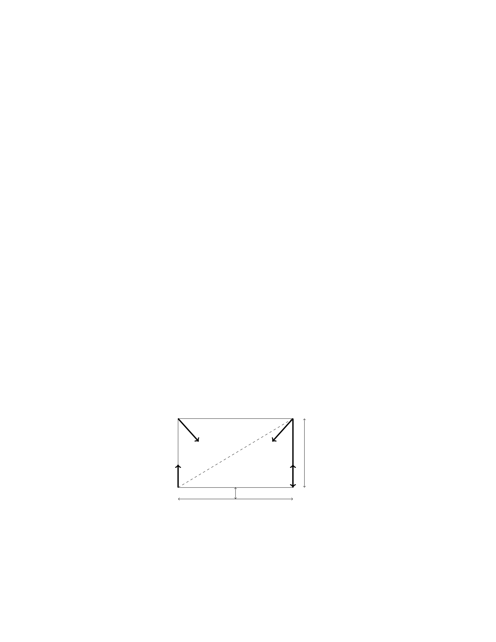
Solution
Step 1: Considering the forces acting on the beam, we can identify two main
components: the gravitational force and the tension force from the cable. Let’s
start by drawing a free-body diagram of the beam.
Step 2: The gravitational force acting on the beam can be broken down into
two components: one parallel to the beam (M g sin θ) and one perpendicular to
the beam (Mg cos θ).
Step 3: The tension force in the cable can be resolved into components
parallel (Tsin θ) and perpendicular (Tcos θ) to the beam.
Step 4: In the vertical direction, the sum of the forces must be zero for the
beam to be in equilibrium. Therefore, we have the following equation:
Tcos θ=Mg cos θ
Step 5: Solving for the tension Tgives:
T=Mg
Step 6: Therefore, the tension in the cable supporting the beam is equal to
the gravitational force acting on the beam, which is Mg.
Question 28
Question
A uniform horizontal beam of length Land weight Wis attached to a vertical
wall by a hinge at one end and holds a weight wat the other end. The beam
makes an angle θwith the vertical. Find an expression for the magnitude of the
force exerted by the hinge on the beam in terms of L,θ,W, and w.
Solution
Step 1: Draw a free-body diagram for the beam.
WFhinge
wN
Ffriction
L
Lsin θ
Lcos θ
Step 2: Write the equations of equilibrium in the xand ydirections. In the
xdirection: XFx= 0 =⇒Fhinge −wsin θ= 0
23

In the ydirection:
XFy= 0 =⇒N−W+wcos θ= 0
Step 3: Solve the equations to find the magnitude of the force exerted by
the hinge on the beam, Fhinge. From the first equation:
Fhinge =wsin θ
Question 29
Question
A uniform meter stick of mass 0.20 kg is supported horizontally at its end by
two strings, each of which is at an angle of 30 degrees with the stick. One string
has a tension of 6.0 N. What is the tension in the other string?
Solution
Step 1: We will start by drawing a free-body diagram of the meter stick. Let
the tension in the first string be T1= 6.0 N and the tension in the second string
be T2. The weight of the meter stick acts downwards at its center (0.50 m) with
a magnitude of mg = 0.20 kg ×9.8 m/s2.
Step 2: The net force in the horizontal direction must be zero for equilibrium.
Therefore, the horizontal components of the tensions in the strings must balance
the horizontal component of the weight. So, T1cos 30◦+T2cos 30◦= 0.
Step 3: The net force in the vertical direction must also be zero for equi-
librium. Therefore, the vertical components of the tensions in the strings must
balance the vertical component of the weight. So, T1sin 30◦+T2sin 30◦=mg.
Step 4: Substituting the given values into the equations, we get:
6.0 cos 30◦+T2cos 30◦= 0
6.0 sin 30◦+T2sin 30◦= 0.20 ×9.8
Step 5: Solving these two equations simultaneously, we find that T2= 9.0 N.
Therefore, the tension in the other string is 9.0 N.
Question 30
Question
A steel cable with a length of 10 m and a diameter of 2 cm is hung vertically
from a support. If the Young’s modulus for steel is 2 ×10¹¹ N/m2, calculate the
elongation of the cable due to its own weight. The density of steel is 7.8×10³
kg/m3.
24

Solution
Step 1: First, calculate the mass of the cable. Given: Density of steel, ρ=
7.8×10³kg/m3= 7.8×10⁻³g/cm3
Diameter of the cable, d= 2 cm = 2 ×10⁻²m
Length of the cable, L= 10 m
The volume of the cable can be calculated using the formula for the volume
of a cylinder:
V=πr2h
where ris the radius and is half of the diameter: r=d
2, and h=L. Thus, the
volume Vof the cable is given by:
V=πd
22
L=π2×10⁻²
22
×10 = π×10−4×10 = π×10−3m3
The mass mof the cable can be calculated using the formula:
m=ρV
Substitute the values of ρand V:
m= 7.8×10³×π×10−3= 7.8×π×100= 7.8πkg
Step 2: Calculate the weight of the cable. The weight Wof the cable is
given by:
W=mg
where gis the acceleration due to gravity. Substitute the values of mand g:
W= 7.8π×9.8 N = 76.44πN
Step 3: Calculate the stress in the cable. The cross-sectional area Aof the
cable can be calculated using the formula for the area of a circle:
A=πr2
Substitute the value of r:
A=πd
22
=π2×10⁻²
22
=π×10−4m2
The stress σin the cable is given by:
σ=F
A
where Fis the force acting on the cable (weight Win this case). Substitute the
values of Wand A:
σ=76.44π
π×10−4=76.44
10−4= 764400 N/m2
25
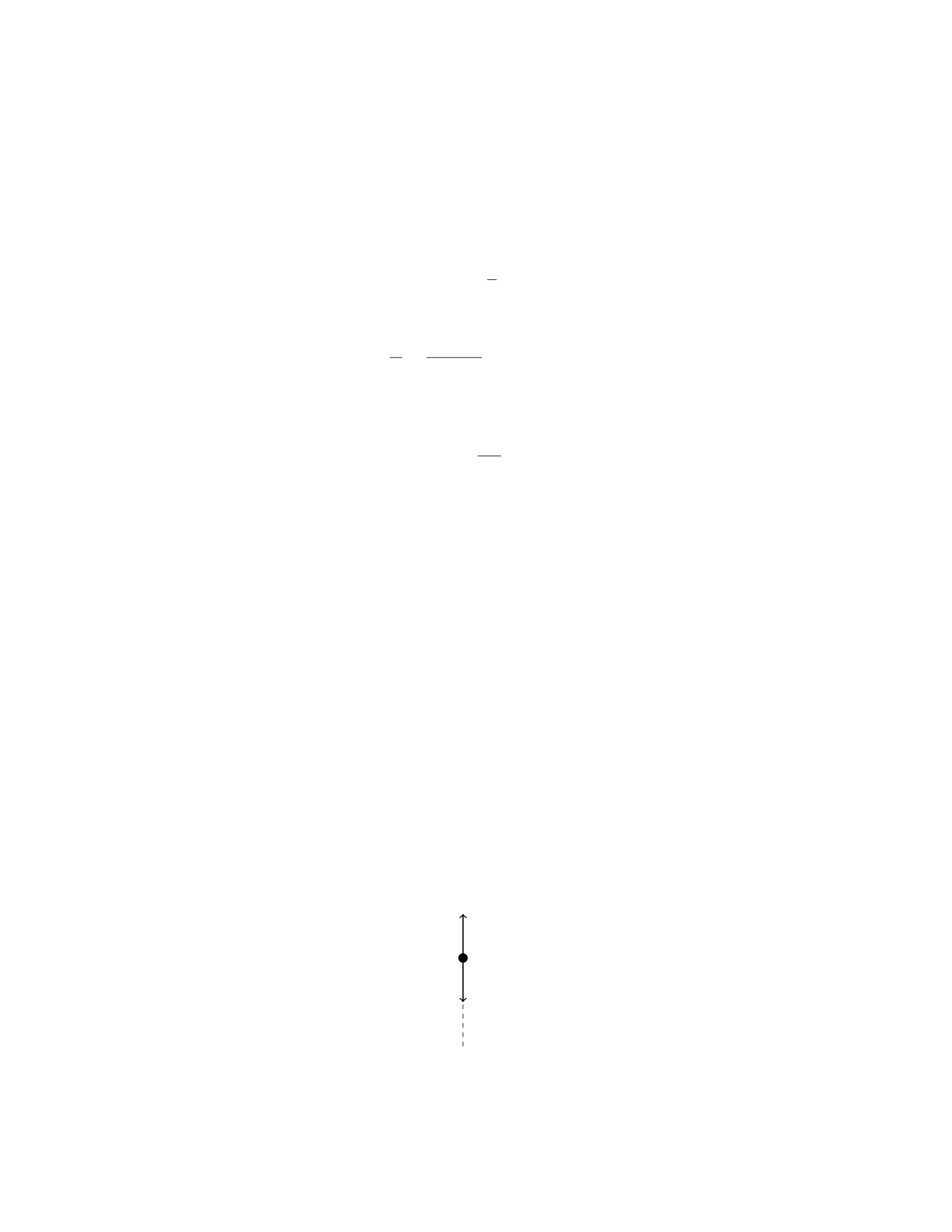
Step 4: Calculate the strain in the cable. The strain εis defined as the ratio
of the change in length ∆Lto the original length L. The Young’s modulus Y
is related to stress and strain by the formula:
Y=σ
ε
Therefore, the strain εcan be expressed as:
ε=σ
Y=764400
2×1011 = 3.822 ×10⁻⁶
Step 5: Calculate the elongation of the cable. The elongation ∆Lof the
cable can be calculated using the formula for strain:
ε=∆L
L
Solving for ∆L:
∆L=ε×L= 3.822 ×10−6×10 = 3.822 ×10⁻⁵m
Therefore, the elongation of the cable due to its own weight is 3.822×
Question 31
Question
A uniform rod of length Land mass Mis hanging vertically from one end, with
the other end fixed. A mass mis attached to the free end of the rod. If the rod
is in equilibrium, determine the tension at the fixed end in terms of L,M,m,
and the acceleration due to gravity, g.
Solution
Let’s consider the forces acting on the rod in equilibrium. There are three forces
acting on the rod: the tension at the fixed end, the weight of the rod, and the
weight of the mass m.
Step 1: Free Body Diagram
First, let’s draw a free body diagram of the rod:
T
Mg
mg
26

Step 2: Write the Equations of Equilibrium
In the vertical direction, the forces must balance out for the rod to be in equi-
librium. Therefore, we have:
T=Mg +mg
Step 3: Using the Given Information
We know that the total length of the rod is L, so the distance from the fixed
end to the center of mass of the rod is L/2. The weight of the rod acts at its
center of mass. The weight of the rod is M g, and it acts at a distance of L/2
from the fixed end. Thus, the torque due to the weight of the rod is
Mg ·L
2
The mass mis attached at the end of the rod, so its weight mg acts at the
end of the rod which is at a distance Lfrom the fixed end. The torque due to
the weight of mass mis
mg ·L
Step 4: Write the Torque Equation
In equilibrium, the net torque about the fixed end of the rod is zero. Therefore,
the torque due to the weight of the rod equals the torque due to the weight of
mass m:
Mg ·L
2=mg ·L
Step 5: Solve for T
Substitute the given relationship for Tinto the torque equilibrium equation:
T=Mg +mg =mg ·L
L
2
= 2mg
Therefore, the tension at the fixed end is 2mg.
Question 32
Question
A rod of length Land uniform density ρis pivoted at one end and held horizon-
tally. A force Fis applied at a distance dfrom the pivot perpendicular to the
rod, causing it to rotate about the pivot. Calculate the angular acceleration of
the rod in terms of the given parameters.
Solution
Step 1: The torque about the pivot point due to the force Fis given by τ=F·d.
Step 2: The moment of inertia of the rod about the pivot point is I=1
3ML2
where M=ρAL and Ais the cross-sectional area of the rod.
27

Step 3: The torque due to the force is also equal to the moment of inertia
times the angular acceleration, τ=I·α.
Step 4: Substituting in the expressions for torque and moment of inertia, we
have F·d=1
3ρALL2α.
Step 5: Solving for the angular acceleration α, we get α=3F
ρAL ·1
L=3F
ρA .
Therefore, the angular acceleration of the rod is α=3F
ρA .
Question 33
Question
A uniform ladder of length Land mass mrests against a smooth vertical wall.
The ladder makes an angle θwith the ground. Find the normal forces exerted
by the wall and the ground on the ladder.
Solution
Step 1: Draw a free body diagram for the ladder. The forces acting on the ladder
are the weight mg, the normal force N1from the wall, and the normal force N2
from the ground. Step 2: Resolve the weight mg into components parallel
and perpendicular to the ladder. The parallel component is mg sin(θ) and the
perpendicular component is mg cos(θ). Step 3: Write down the equations of
equilibrium for the ladder:
XFx=0:N1=mg sin(θ)
XFy=0:N2=mg cos(θ)
Therefore, the normal force exerted by the wall on the ladder is N1=mg sin(θ)
and the normal force exerted by the ground on the ladder is N2=mg cos(θ).
Question 34
Question
A uniform steel beam of length L= 8.00 m is to be supported by two cables
attached at the ends of the beam. If the beam has a mass of 500 kg, determine
the tension in each cable when a 2000 kg mass is suspended at the middle of
the beam. Assume the beam weighs 10 N per meter.
Solution
Step 1: Draw a free-body diagram for the steel beam and the masses. Let T1
and T2be the tensions in the cables at each end of the steel beam.
28
Step 2: Write the equation for the sum of the forces in the vertical direction.
The beam is in equilibrium, so the sum of the forces in the vertical direction
must be zero.
The forces acting vertically are: - The weight of the beam: Wbeam =mg =
(500 kg ×9.8 m/s2) N = 4900 N - The weight of the attached mass: Wmass =
mg = (2000 kg ×9.8 m/s2) N = 19600 N - The tension in cable 1 (T1) acting
upwards - The tension in cable 2 (T2) acting upwards
Now, we can write the equation for the sum of forces in the vertical direction:
T1+T2−Wbeam −Wmass = 0
Step 3: Find the weight of the beam. The weight of the beam is given as 10 N
per meter and the length of the beam is 8.00 m. Wbeam = (10 N/m ×8.00 m) =
80 N
Step 4: Substitute the values into the equation. T1+T2−4900 N−19600 N =
0
Step 5: Solve for T1and T2. Since the mass is located at the middle of the
beam, the beam is balanced and T1=T2.
2T−24500 N = 0 2T= 24500 N T= 12250 N
Therefore, the tension in each cable is 12250 N.
Question 35
Question
A uniform rod of length Land mass Mis supported at its ends by two vertical
strings. A weight Wis placed at a distance xfrom one end of the rod, where
0< x < L. The tension in the left string is twice that in the right string. Find
the tensions in the two strings.
Solution
Step 1: Draw a free body diagram of the rod. Let TLbe the tension in the left
string and TRbe the tension in the right string.
Step 2: Set up the equilibrium equations in the vertical direction:
(TL+TR=Mg
TL= 2TR
Step 3: Substitute TL= 2TRinto the first equation:
2TR+TR=Mg =⇒3TR=M g =⇒TR=Mg
3
Step 4: Now, find TLusing TL= 2TR:
TL= 2 ·Mg
3=2Mg
3
Step 5: Therefore, the tension in the left string TL=2Mg
3and the tension
in the right string TR=Mg
3.
29

