



PHYS 231 - UNIVERSITY PHYSICS I
- Equilibrium and Elasticity
Question Bank - Set 2
Liberty University
Question 1
Question
A horizontal spring with spring constant k= 500 N/m is attached to a wall. A
block of mass m= 2 kg is pressed against the free end of the spring, compressing
it by 10 cm. The static friction coefficient between the block and the surface
is µs= 0.4. Find the minimum force Fthat should be applied to the block
horizontally to overcome static friction and start moving the block to the right.
Solution
Step 1: The force exerted by the spring can be found using Hooke’s law:
Fspring =kx, where kis the spring constant and xis the compression of the
spring. Substitute k= 500 N/m and x= 10 cm = 0.10 m:
Fspring = (500 N/m)(0.10 m) = 50 N
Step 2: The force of static friction acting on the block when F= 0 is
fs=µsN, where Nis the normal force. The normal force Ncan be found by
balancing forces in the vertical direction:
N−mg = 0
N=mg = (2 kg)(9.8 m/s2) = 19.6 N
Step 3: The minimum force Fmin required to overcome static friction is equal
to the force of static friction:
Fmin =fs=µsN= (0.4)(19.6 N) = 7.84 N
Therefore, the minimum force Fthat should be applied to the block hori-
zontally to overcome static friction and start moving it to the right is 7.84 N .

Question 2
Question
A uniform wooden beam of length Land mass Mrests horizontally on two
supports, one at each end. A person weighing Wstands at a distance dfrom
one of the supports. Determine the magnitude and direction of the force exerted
by the support closer to the person.
Solution
Step 1: Begin by drawing a free-body diagram of the beam. Label the supports
as A and B, and the person as P, with forces
FA,
FB, and
Wacting on the
beam. The weight of the beam can be treated as acting at the center of mass,
resulting in a force
Fg=−Mgˆ
j.
Step 2: Write down the equilibrium conditions for the beam. Considering
the forces in both horizontal and vertical directions, we have:
XFx=0:FA=FB
XFy=0:FA+FB=Mg
Step 3: Now consider the torque equation about the support at A. The
torque due to the forces at B, P, and the beam’s weight all contribute:
τA=0=−FB
L
2+W d −Mg L
2
Step 4: Use the equations derived to solve for the value of the force FB
exerted by the support at B:
FB=W d
2L+Mg
2
Step 5: Substitute the expression for FBback into the equation PFx= 0,
to find the value of the force FAexerted by the support at A:
FA=W d
2L+Mg
2
Step 6: Therefore, the magnitude of the force exerted by the support closer
to the person is W d
2L+Mg
2, directed upwards.
Question 3
Question
A uniform rod of length Land mass Mis suspended horizontally from one end.
A weight of mass mis hung from the other end. If the rod has a density ρ, find
the force Frequired to keep the rod horizontal.
2

Solution
Step 1: Begin by identifying the forces acting on the rod. We have the force
of tension Tpulling upwards at the end where the weight is hung, the force of
gravity Mg acting downwards at the center of the rod, and the force Facting
horizontally at the end where the rod is suspended. Step 2: Calculate the
torque produced by the weight mabout the suspension point. The torque τ
due to the weight mis τ=mL
2g, where L
2is the distance from the suspension
point to the weight m. This torque causes a counterclockwise rotation. Step
3: Calculate the torque produced by the force Fabout the suspension point.
The torque τ′due to the force Fis τ′=F·L, where Lis the length of the
rod. This torque causes a clockwise rotation to balance the torque from the
weight m. Step 4: Set up the equilibrium condition for torques. For the rod
to be in equilibrium, the net torque acting on it must be zero. Thus, we have
τ−τ′= 0. Step 5: Substitute the expressions for τand τ′into the equilibrium
condition. We get mL
2g−F L = 0. Step 6: Solve for the force F. Rearranging
the equation, F=m·L·g
2. Therefore, the force Frequired to keep the rod
horizontal is F=m·L·g
2.
Question 4
Question
A uniform beam of length Land mass Mis supported by a pivot at one end
and a vertical wall at the other end. A weight of mass mis hung from a point
3L
4along the beam. Find the tension in the pivot and the force exerted by the
wall on the beam.
Solution
Step 1: Draw a free-body diagram of the beam.
Step 2: Write down the equilibrium condition in the vertical direction. The
sum of forces in the vertical direction must be zero.
T+N−Mg −mg = 0
Step 3: Write down the torque balance equation about the pivot point (point
A). The sum of torques about any point must be zero.
mg 3L
4−Mg(L) = 0
3

Step 4: Solve the system of equations.
(T+N=Mg +mg
mg 3L
4−Mg(L) = 0
Let’s denote Tas the tension in the pivot and Nas the force exerted by the
wall on the beam.
Step 5: Solve for Nin terms of Tfrom the first equation.
N=Mg +mg −T
Step 6: Substitute N=Mg +mg −Tinto the torque balance equation.
mg 3L
4−Mg(L) = 0
Step 7: Solve for Tby substituting N=Mg +mg −T.
mg 3L
4−Mg(L) = 0
mg 3L
4−Mg(L) = 0
T= 3mg −Mg
Therefore, the required tension in the pivot is 3mg −Mg and the force
exerted by the wall on the beam is Mg +mg −(3mg −Mg).
Question 5
Question
A uniform solid cylinder of mass Mand radius Ris held in place on a rough
horizontal surface by a horizontal force
Fapplied at a distance habove the
center of the cylinder (see Figure 1). The coefficient of static friction between
the cylinder and the surface is µs. Determine the minimum magnitude Fmin of
the force
Frequired to hold the cylinder in place.
cylinder_force.png
Solution
Step 1: We start by drawing a free-body diagram of the cylinder. The forces
acting on the cylinder are the gravitational force
Wdownward, the normal force
Nperpendicular to the surface, the static friction force
fspointing to the left,
and the external force
Fpointing to the right.
4

Step 2: We can see that the net force acting on the cylinder in the horizontal
direction must be zero for equilibrium:
F−fs= 0
Step 3: The friction force can have a maximum magnitude of µsN, where
Nis the magnitude of the normal force. In this case, Nmust balance the
gravitational force W. The normal force Ncan be calculated using the sum of
torques about the point of contact with the surface:
N=Mg
2+F h
Step 4: The friction force can now be expressed in terms of F:
fs=µsN=µsMg
2+F h
Step 5: Substituting this expression for fsinto the equation from Step 2
gives:
F−µsMg
2+F h= 0
Step 6: Solving for Fgives:
F=µsMg
2 + µsh
Therefore, the minimum magnitude Fmin of the force
Frequired to hold the
cylinder in place is µsMg
2+µsh.
Question 6
Question
A steel cable of length 10 m and diameter 2 cm is hung vertically from a fixed
support. A weight of 500 N is suspended from the bottom end of the cable.
Calculate the elongation of the cable due to the weight.
Solution
Step 1: Calculate the cross-sectional area of the steel cable using the formula
for the area of a circle: A=πr2, where ris the radius of the cable. Given
that the diameter of the cable is 2 cm, the radius ris 1 cm = 0.01 m. Thus,
A=π(0.01 m)2= 3.14 ×10⁻⁴m2.
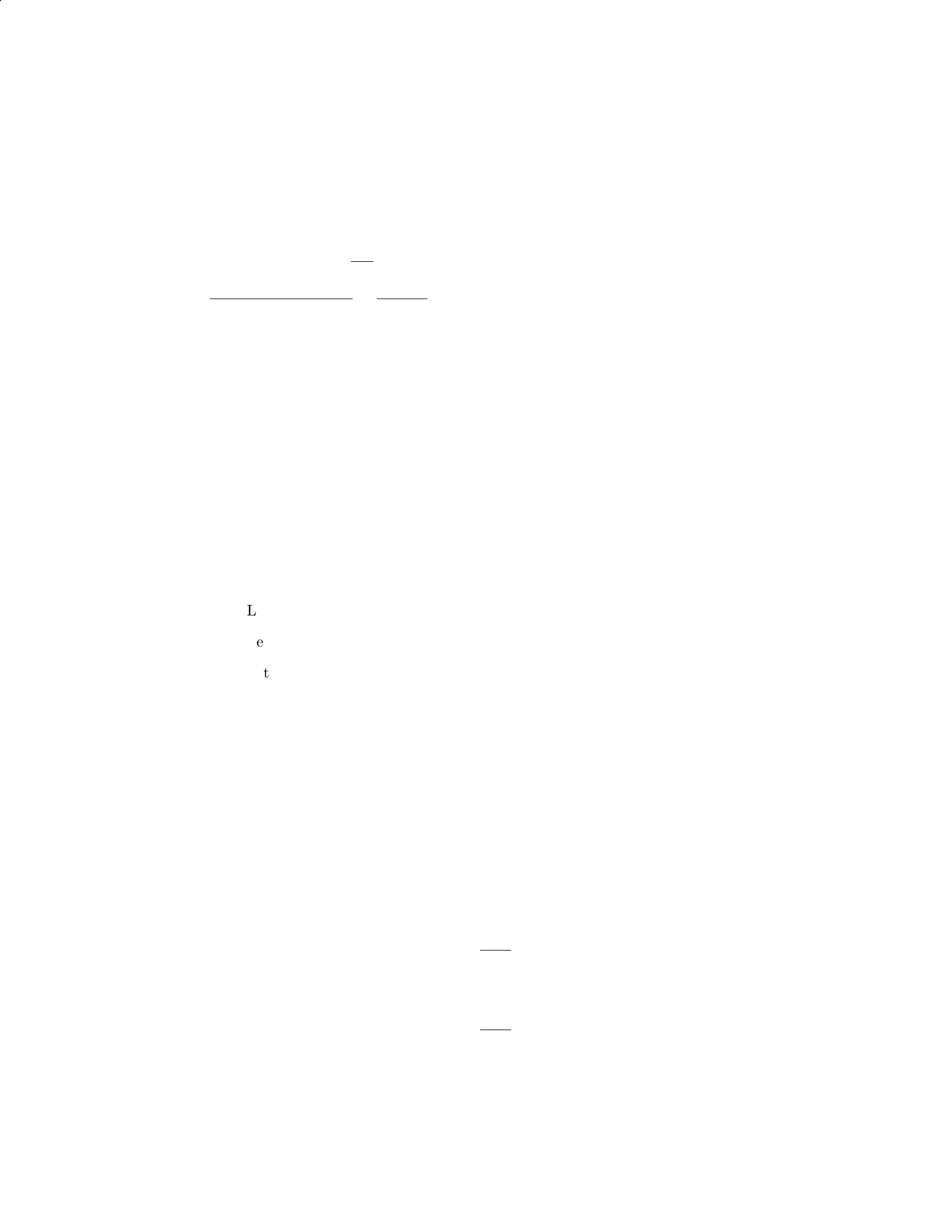
Step 2: Calculate the stress on the cable using the formula: σ=F
A, where F
is the force applied to the cable. Given that the force Fis 500 N, and the cross-
sectional area Ais 3.14 ×10⁻⁴m2, we have: σ=500 N
3.14×10⁻⁴m2≈1.59 ×10⁶Pa.
5
Step 3: Determine the Young’s modulus for steel, which is approximately
2×10¹¹ Pa.
Step 4: Calculate the elongation of the cable using the formula for linear
deformation: ∆L=F·L
A·E, where Lis the original length of the cable and Eis
the Young’s modulus for steel. Substitute the values into the formula: ∆L=
500 N×10 m
3.14×10⁻⁴m2×2×1011 Pa =5000
6.28×10⁷≈7.94 ×10⁻⁵m.
Therefore, the elongation of the cable due to the weight is approximately
7.94 ×10⁻⁵m or 0.0794 mm.
Question 7
Question
A uniform horizontal beam of length Land mass Mis attached to a vertical
wall by a hinge at one end and supported by a cable making an angle θwith
the beam. The other end of the cable is attached to the beam a distance xfrom
the hinge. Find the tension in the cable and the force exerted on the hinge.
Solution
Step 1: Draw a free-body diagram of the beam.
Let FHbe the horizontal force exerted on the beam by the hinge.
Let FTbe the tension in the cable.
Let Wbe the weight of the beam acting at its center.
Step 2: Write the torque equation about the hinge point.
FT·xsin θ= (L/2) ·W
Step 3: Write the force equation in the vertical direction.
FT·cos θ=W
Step 4: Write the force equation in the horizontal direction.
FH=FT·sin θ
Step 5: Solve for the tension FT.
FT=W
cos θ
Step 6: Substitute W=Mg and simplify.
FT=Mg
cos θ
6

Step 7: Solve for the horizontal force FH.
FH=Mg
cos θ·sin θ
Therefore, the tension in the cable is FT=M g
cos θand the force exerted on the
hinge is FH=Mg
cos θ·sin θ.
Question 8
Question
A uniform wooden beam of length Land mass Mis attached to a wall by a
hinge at one end, with a weight Whanging from the other end. The beam
makes an angle θwith the horizontal such that it is in equilibrium. The beam
has a moment of inertia Iabout its end where the weight is hanging. Determine
the tension in the hinge and the reaction force at the hinge.
Solution
Step 1: Draw a free-body diagram of the beam.
XFx=0:T−Rsin θ= 0
XFy=0:Rcos θ−W= 0
Step 2: Solve for Tand R. From the first equation:
T=Rsin θ
Substitute this expression into the second equation:
Rcos θ−W= 0
R=W
cos θ
Step 3: Calculate the moment of inertia I. The moment of inertia about the
end where the weight is hanging is given as I. For a beam of length Land mass
M, the moment of inertia about the end is 1
3ML2.
Step 4: Consider the torque equation about the hinge.
Xτ=Iα = 0
r×F=Iα
rT =I¨
θ
Lsin θ·R=1
3ML2¨
θ
7
Step 5: Solve for ¨
θ.
R=W
cos θ
Lsin θ·W
cos θ=1
3ML2¨
θ
LW tan θ=1
3ML2¨
θ
¨
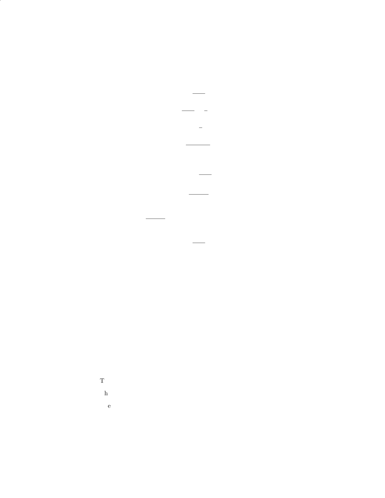
θ=3Wtan θ
L
Step 6: Calculate tension in the hinge.
T=Rsin θ=W
cos θsin θ
T=Wsin θ
cos θ
T=Wtan θ
Since we have ¨
θ=3Wtan θ
L, it means the tension in the hinge is T= 3W.
Step 7: Calculate the reaction force at the hinge.
R=W
cos θ
R=Wsec θ
Therefore, the tension in the hinge is 3Wand the reaction force at the hinge
is Wsec θ.
Question 9
Question
A block of mass mis placed on an inclined plane with an angle of elevation θ.
The block remains stationary with respect to the inclined plane. Determine the
coefficient of static friction µsbetween the block and the inclined plane.
Solution
Step 1: Draw a Free Body Diagram (FBD) of the block on the inclined plane.
The weight of the block mg acts downward.
The normal force Nacts perpendicular to the inclined plane.
The frictional force fsacts parallel to the inclined plane in the opposite
direction of motion.
8
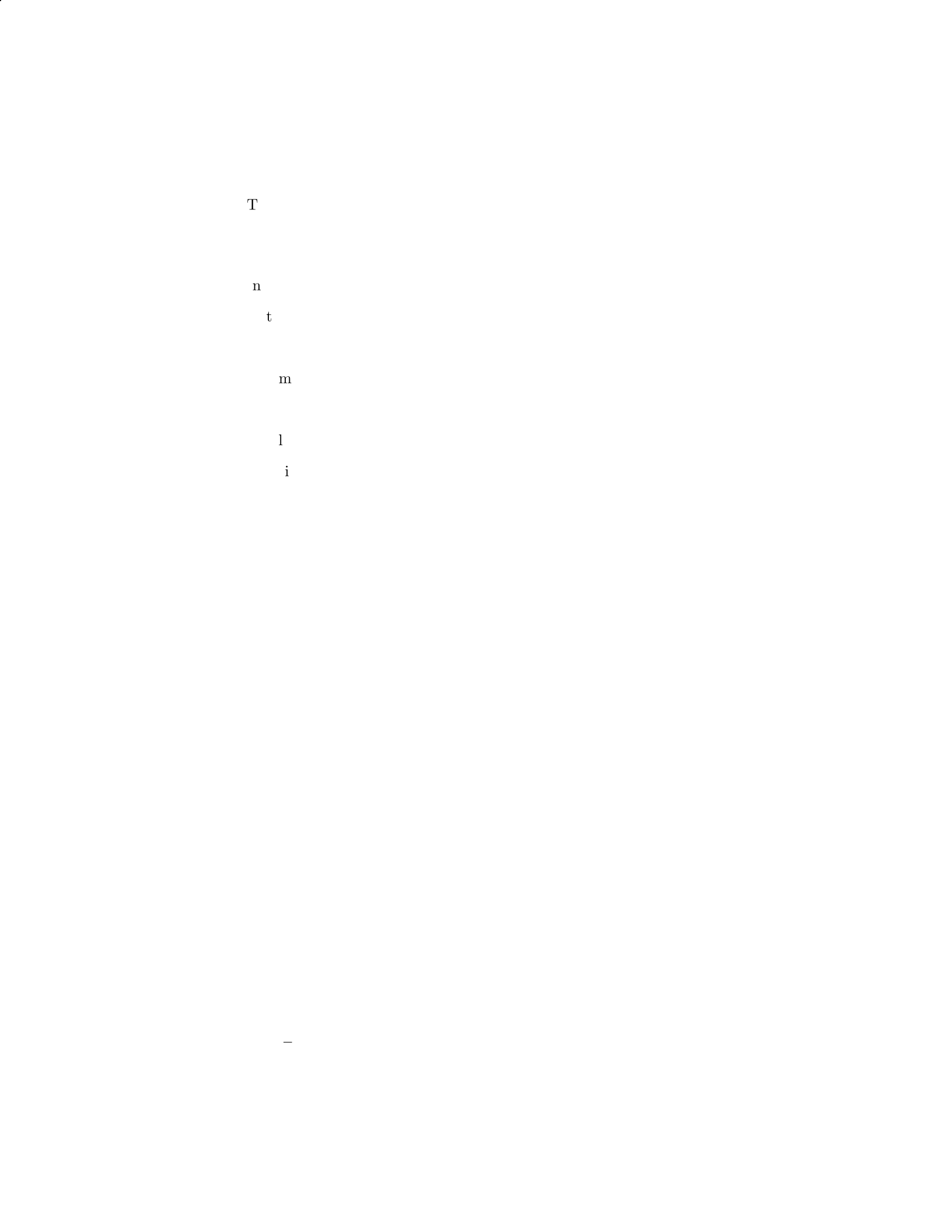
The component of the weight mg sin θacts parallel to the inclined plane
in the direction of motion.
Step 2: Write the force balance equations.
In the perpendicular direction: N=mg cos θ.
In the parallel direction: fs=mg sin θ.
Step 3: Determine the maximum value of static friction.
The maximum value of static friction is fmax =µsN=µsmg cos θ.
Step 4: Set up the equilibrium condition in the parallel direction.
Equilibrium condition: fmax =mg sin θ.
Substituting fmax =µsmg cos θand mg sin θinto the equilibrium condi-
tion gives µs= tan θ.
Therefore, the coefficient of static friction µsbetween the block and the
inclined plane is µs= tan θ.
Question 10
Question
A uniform beam of length Land mass Mis supported by a cable attached x
distance along the beam from one end. The beam makes an angle θwith the hor-
izontal. Given that the tension in the cable is Tand the beam is in equilibrium,
determine an expression for the distance xwhere the cable is attached.
Solution
Step 1: Draw a free body diagram of the forces acting on the beam.
XFy=T−Mg cos θ= 0
XFx=N−Mg sin θ= 0
Step 2: Solve for the normal force N. From the sum of the forces in the
x-direction, we have:
N=Mg sin θ
Step 3: Consider the torque about the end of the beam where the cable is
attached. The torque due to the weight of the beam about this point is given
by:
τ=Mgd sin θ
where d=L
2−x.
9

Step 4: Set up equilibrium condition for the torque. For the beam to be in
equilibrium, the sum of the torques must be zero:
τ= 0
T(x)−Mg(d) sin θ= 0
T(x) = Mg(L
2−x) sin θ
Step 5: Determine the expression for x. Since the beam is in equilibrium,
the tension in the cable is equal to the tension at the other end when pulling
the beam in the opposite direction:
T=Mg(L
2+x) sin θ
Mg(L
2−x) sin θ=Mg(L
2+x) sin θ
x=L
4
Therefore, the cable should be attached a distance x=L
4along the beam
from one end.
Question 11
Question
A uniform rod of length Land mass mis attached to a wall via a pivot at one
end. A force Fis applied perpendicular to the rod at a distance xfrom the
pivot. Find the magnitude and direction of the force required to keep the rod
in equilibrium.
Solution
To find the magnitude and direction of the force required to keep the rod in
equilibrium, we need to consider the torques acting on the rod and set them
equal to zero since the rod is not rotating.
Step 1: Identify the forces and torques. Let’s denote the pivot point
as O and the point of application of the force as P. The forces acting on the
rod are the gravitational force mg acting at the center of mass of the rod, the
normal force Nexerted by the pivot, and the applied force F. The torque due
to the normal force will be zero since its line of action passes through the pivot.
Step 2: Express the torques as a function of the variables. The
torque due to the gravitational force and the applied force are given by:
τgrav =−mg L
2sin θ
10
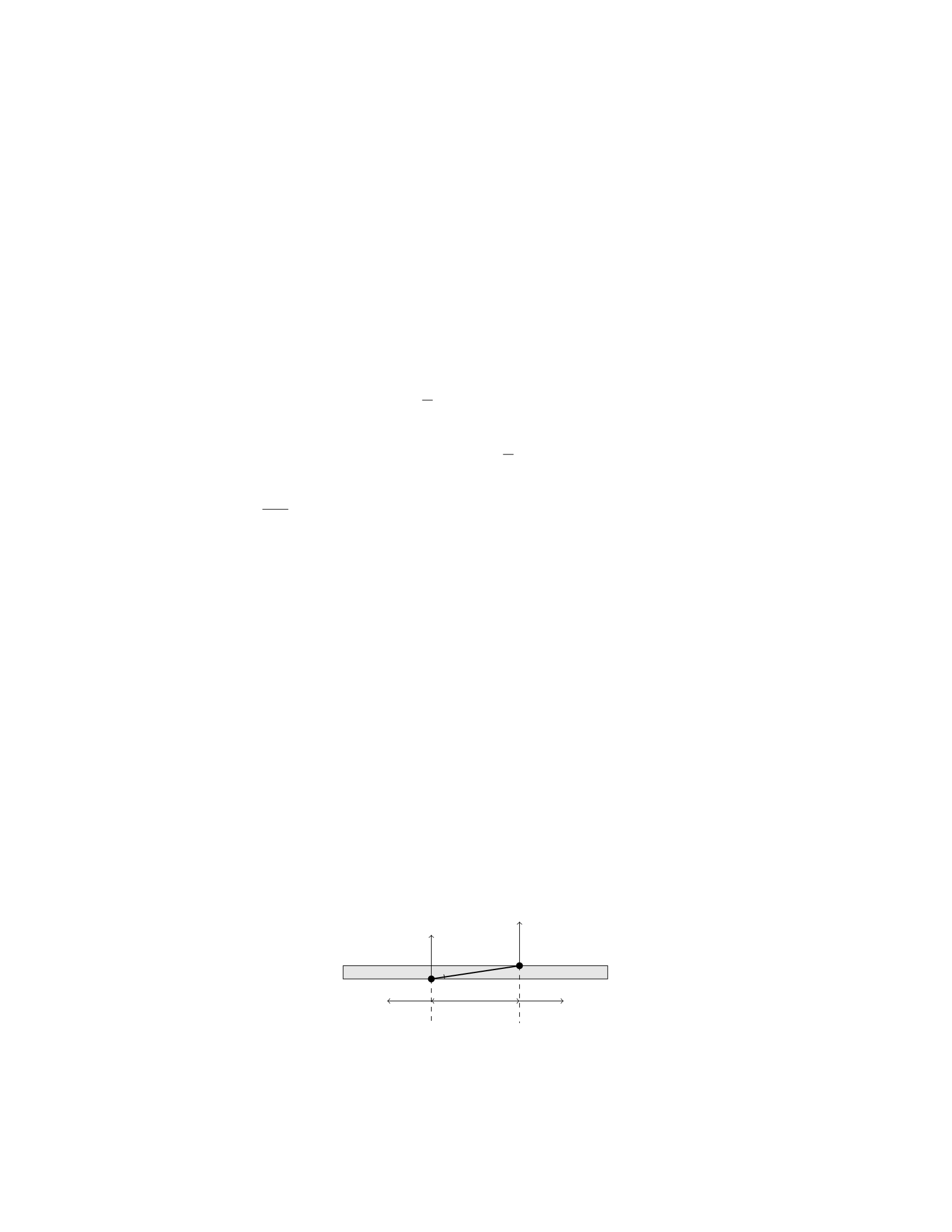
τF=F x sin θ
where θis the angle between the force and the rod.
Step 3: Set the total torque equal to zero. Since the rod is in equilib-
rium, the total torque about the pivot point O must be zero. Thus, we have:
τgrav +τF= 0
Step 4: Solve for the force F.Substitute the expressions for τgrav and
τFinto the equation and solve for F:
−mg L
2sin θ+F x sin θ= 0
F x =mg L
2
Therefore, the magnitude of the force required to keep the rod in equilibrium
is F=mgL
2x. The direction of the force will be perpendicular to the rod at a
distance xfrom the pivot.
Question 12
Question
A uniform beam of length Land mass Mis supported by two ropes attached
at points Aand Blocated at distances xand yfrom one end of the beam,
respectively. The tension in each rope is T. If the beam is in equilibrium and
the angle between the beam and the horizontal is θ, determine the tensions in
the ropes in terms of M,L,x,y, and θ.
Solution
Step 1: Draw a free-body diagram of the beam. Step 2: Write out the force
equilibrium equations in the xand ydirections. Step 3: Solve for the tensions
in the ropes in terms of M,L,x,y, and θ.
Step 1:
Let’s start by drawing a free-body diagram of the beam.
L
AB
T T
Mg Mg
θ
11
Step 2:
In the xdirection:
Tsin(θ)=0
In the ydirection:
2Tcos(θ)−2Mg = 0
Step 3:
From Tsin(θ) = 0, we find T= 0.
Then, substitute T= 0 into 2Tcos(θ)−2M g = 0 to find Mg = 0, which is
not possible for equilibrium.
Therefore, the only solution is T= 0, meaning the beam is not supported
by the ropes in equilibrium.
Question 13
Question
A uniform beam of length Land mass Mis supported by a vertical cable at a
distance dfrom one end. The beam makes an angle θwith the horizontal. Find
the tension in the cable.
Solution
Step 1: Draw a free-body diagram of the beam.
The weight Mg acts at the center of the beam downward.
The tension Tin the cable acts upward at an angle θto the vertical.
The normal force Nacts upward at the point of support.
Step 2: Write the equations of equilibrium in the vertical and horizontal
directions.
Vertical direction: N−Mg cos(θ)=0
Horizontal direction: T−Mg sin(θ)=0
Step 3: Solve the equations of equilibrium to find the tension in the cable.
From the vertical equilibrium equation, we can solve for the normal force: N=
Mg cos(θ).
Substitute the normal force into the horizontal equilibrium equation: T−
Mg sin(θ)=0
Therefore, T=Mg sin(θ).
So, the tension in the cable is T=Mg sin(θ).
12

Question 14
Question
A uniform beam of length Land mass Mis supported by a pivot at one end,
while the other end is connected to a cable that makes an angle θwith the
horizontal. The cable applies a tension force Tto the beam to keep it in equi-
librium. Find the tension in the cable and the reaction force at the pivot in
terms of M,L,g, and θ.
Solution
Step 1: Draw a free body diagram of the beam. There are two forces acting
on the beam: the tension force Tand the gravitational force Mg acting at the
center of mass of the beam.
Step 2: Resolve the forces into components. The tension force Tcan be
resolved into horizontal and vertical components: Tx=Tsin(θ) and Ty=
Tcos(θ).
Step 3: Write the equilibrium equations in the horizontal and vertical direc-
tions:
In the horizontal direction: Tx= 0
In the vertical direction: Ty−Mg = 0
Step 4: Solve the equations from Step 3 to find the tension Tand the reaction
force at the pivot:
From Tx= 0, we have Tsin(θ) = 0, which implies T= 0 (since sin(θ)= 0
for θ= 0).
From Ty−Mg = 0, we have Tcos(θ)−M g = 0, which implies T=M g
cos(θ).
Therefore, the tension in the cable is T=M g
cos(θ)and there is no reaction
force at the pivot since the tension force balances the gravitational force.
Question 15
Question
A uniform rod of length Land mass Mis placed horizontally on two supports.
A block of mass mis hung from a distance dof one end of the rod. If the rod
is on the verge of tipping, find the coefficient of static friction µsbetween the
rod and the supports.
Solution
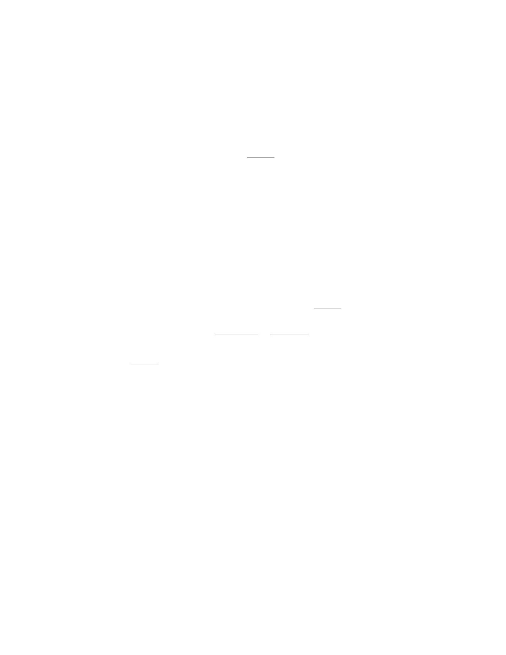
1. Let’s begin by drawing a free-body diagram of the rod. The forces acting on
the rod are the gravitational force M g acting at the center of mass, the normal
forces N1and N2at the supports, the weight of the block mg acting downward
at a distance dfrom the left support, and the frictional force facting at the
right support.
13
2. Since the rod is on the verge of tipping, the sum of torques about the
left support must be zero. We can set up the equation for torque equilibrium
as follows:
f·L=mg ·d
f=m·g·d
L
3. To prevent the rod from tipping, the horizontal force at the supports
must provide a counter-clockwise torque that balances the clockwise torque due
to the block. This gives us the equation:
N1=N2+Mg
4. In the vertical direction, the net force must be zero:
N1+N2=Mg +mg
5. The maximum frictional force that can be applied is µsN1, since the rod
is just on the verge of tipping. Using the equations from steps 3 and 4, we can
express this maximum frictional force in terms of m,g, and d:
µsN1=µs(Mg +mg) = µs(g(M+m) = m·g·d
L
µs=m·g·d
Lg(M+m)=md
L(M+m)
So, the coefficient of static friction between the rod and the supports is
µs=md
L(M+m).
Question 16
Question
A long rod of length Land mass Mis pivoted at one end. A force Fis applied
at a distance xfrom the pivot point in a direction perpendicular to the rod.
Determine the force Fneeded to hold the rod in equilibrium, assuming the rod
is uniform and has a negligible mass compared to the force F.
Solution
To solve this problem, we will analyze the torques acting on the rod and set
them equal to zero since the rod is in equilibrium.
Step 1: Define the torque equation. The torque (τ) acting on the rod
due to the force Fis given by:
τ=F x
14
The torque due to the gravitational force acting at the center of mass of the
rod is:
τgravity =MgL
2
The torque due to the force of gravity acting at the distance xfrom the pivot
point is:
τgravity =Mgx
Step 2: Set up the equilibrium condition. For the rod to be in equi-
librium, the sum of the torques acting on it must be zero:
F x −Mgx −MgL
2= 0
Step 3: Solve for the force F.Substitute the expressions for the torques
into the equilibrium condition and solve for F:
F x −Mgx −MgL
2= 0
F x =Mgx +MgL
2
F=Mg +M
2
Thus, the force Fneeded to hold the rod in equilibrium is F=Mg +M
2.
Question 17
Question
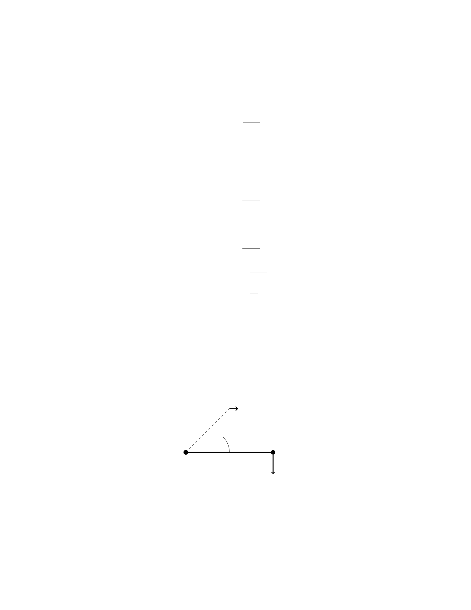
A uniform beam of length Land mass Mis supported by a cable attached to
one end of the beam, as shown in the figure below. The cable makes an angle θ
with the horizontal. What is the tension in the cable?
L
θ
T
W
15

Solution
Step 1: Find the forces acting on the beam. Since the beam is in equilibrium,
the sum of the forces in the horizontal and vertical directions must be zero. In
the vertical direction:
Tcos θ=Mg
In the horizontal direction:
Tsin θ= 0
Step 2: Solve for the tension in the cable. From the horizontal equilibrium
equation, we have:
Tsin θ= 0
T= 0
Therefore, the tension in the cable supporting the beam is zero.
Question 18
Question
A rigid rod of length Lis suspended horizontally from one end. A weight of
mass mis attached to the free end of the rod. The rod has a mass per unit
length λand a moment of inertia about its center of mass I. Determine the
tension at the point of attachment.
Solution
Step 1: We will first find an expression for the torque due to the weight of the
rod.
The torque due to the weight of the rod about the point of attachment is
given by τrod =1
2λLg. This can be obtained by integrating the weight of each
infinitesimal segment of the rod about the point of attachment and summing
the torques.
Step 2: Next, we will find an expression for the torque due to the weight
attached to the free end of the rod.
The torque due to the weight attached to the free end is τweight =mgL.
Step 3: We need to find the tension Tat the point of attachment. For
equilibrium, the sum of the torques about the point of attachment must be
zero.
Therefore, τrod +τweight −LT = 0.
Substitute the expressions for τrod and τweight into the equation above to
get:
1
2λLg +mgL −LT = 0.
Step 4: Solve for the tension T.
T=1
2λg +mg.
Hence, the tension at the point of attachment is T=1
2λg +mg.
16
Question 19
Question
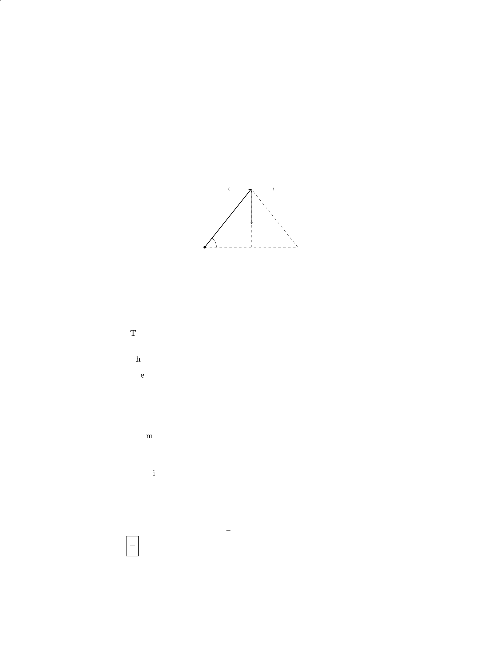
A uniform beam of length Land mass Mis supported by a cable attached at
its midpoint. The beam makes an angle θwith the horizontal, as shown in the
figure below:
L/2
Ft
Fg
T
θ
Given that the tension in the cable is Tand the force due to gravity is
Fg=Mg, determine the angle θin terms of T,M,g, and L. Assume that the
beam is in equilibrium.
Solution
Step 1: Decompose the forces acting on the beam.
The weight of the beam acts downward at the center, with a magnitude
of Fg=Mg.
The tension in the cable acts upward at an angle θfrom the horizontal.
The normal force from the beam’s support can be decomposed into hori-
zontal and vertical components. The force exerted by the support cancels
out the horizontal component of the tension, leaving only the vertical
component.
Step 2: Write out the force balance equations.
Summing forces in the vertical direction:
Tsin(θ) = Mg
Summing forces in the horizontal direction:
Tcos(θ)=0
Step 3: Solve for θ. From the horizontal force balance equation, Tcos(θ) = 0,
which gives T= 0 or cos(θ) = 0. Since Tcannot be zero for equilibrium, we
have cos(θ) = 0. Therefore, θ=π
2. Thus, the angle θin terms of T,M,g, and
Lis π
2.
17

Question 20
Question
A uniform beam of length Land mass Mis supported by two ropes attached at
its ends. A weight of Wis placed at a distance 2
3Lfrom one end of the beam.
If the tension in the rope at the end where the weight is placed is three times
the tension in the other rope, determine the value of W.
Solution
Step 1: Draw a free-body diagram of the beam. Let T1 and T2 be the tensions
in the ropes, and Rbe the reaction force at the support. Also, let xbe the
distance from the left end to the weight W.
Step 2: Write out the force equations along the y-direction. Summing the
forces in the vertical direction, we have:
T1 + T2 = Mg
Step 3: Write out the torque equation. The beam is in equilibrium, so the
sum of the torques about any point must be zero. Taking the point of rotation
at the left end, we have:
T1·2L
3−W·2L
3= 0
Step 4: Express T1 in terms of T2 and solve for W. Since we are given that
T1=3T2, we can substitute T1=3T2 into the torque equation:
3T2·2L
3−W·2L
3= 0
2T2−W
3= 0
W= 6T2
Step 5: Substitute back T1 + T2 = Mg and solve for W. Substitute T1 =
3T2 into T1 + T2 = Mg:
3T2 + T2 = Mg
4T2 = Mg
T2 = M g
4
Therefore, substituting T2 = M g
4into W= 6T2, we find:
W= 6 ×Mg
4=3Mg
2
So, the weight Wis 3
2times the weight of the beam Mg.
18

Question 21
Question
A uniform wooden beam of length Land mass Mis supported by two ropes
attached 1/3 and 2/3 of the way from one end. If the angle the ropes make with
the beam are θ1and θ2, respectively, find the tension in each rope.
Solution
Step 1: Draw the free body diagram of the beam.
Step 2: Resolve the forces into components.
Let T1be the tension in the rope making an angle θ1with the beam, and
T2be the tension in the rope making an angle θ2with the beam. The vertical
components of these forces balance the weight of the beam, and the horizontal
components balance each other due to equilibrium.
Step 3: Write the force equations.
For equilibrium in the vertical direction:
T1cos θ1+T2cos θ2=Mg
For equilibrium in the horizontal direction:
T1sin θ1=T2sin θ2
Step 4: Solve the force equations.
From the horizontal equilibrium equation, we have:
T1=T2
sin θ2
sin θ1
Substitute the expression for T1into the vertical equilibrium equation:
T2
sin θ2
sin θ1
cos θ1+T2cos θ2=Mg
Simplify the equation:
T2=Mg
sin θ2
sin θ1cos θ1+ cos θ2
Thus, the tension in each rope is T1=T2sin θ2
sin θ1and T2=Mg
sin θ2
sin θ1cos θ1+cos θ2
.
Question 22
Question
A uniform rectangular beam of length Land mass Mis supported by two
identical ropes attached to its ends. If the angle between the beam and each
rope is θ, find the tension in each rope.
19

Solution
Let’s denote the tension in each rope as T, the weight of the beam as W, and
the angle between the beam and each rope as θ. We will analyze the forces
acting on the beam in the vertical and horizontal directions.
Step 1: Analyzing forces in the vertical direction: The forces in the vertical
direction are the tension in each rope (2T) and the weight of the beam (W).
The weight can be expressed as W=Mg, where gis the acceleration due to
gravity.
XFy= 2Tcos θ−Mg = 0
2Tcos θ=Mg
T=Mg
2 cos θ
Step 2: Analyzing forces in the horizontal direction: Since the beam is in
equilibrium, there is no net force in the horizontal direction. Therefore, the
horizontal components of the tensions in the ropes balance each other.
XFx= 2Tsin θ= 0
Since the horizontal components of the tensions cancel each other out, there is
no acceleration in the horizontal direction.
Step 3: Final answer: The tension in each rope supporting the beam is
Mg
2 cos θ.
Question 23
Question
A uniform beam of mass Mand length Lis supported by a pivot at its center.
A block of mass mis placed on the left end of the beam. The beam is in
equilibrium with the block hanging vertically below the right end of the beam.
What is the mass of the beam if the tension in the string supporting the block
is equal to one-quarter the weight of the block?
Solution
1. To begin, let’s denote the mass of the uniform beam as Mand the mass of
the block as m. The center of mass of the beam is at L/2 from the pivot point.
2. We can start by writing down the equation for the torque about the pivot
point. Taking the counterclockwise direction as positive, we have:
Xτ= 0
3. The torque due to the block hanging on the right end of the beam is
given by mg L
2. Since the string supporting the block is at an angle, we can
20

break it into two components - one vertical and one horizontal component. The
vertical component provides the tension, and the horizontal component provides
no torque.
4. Given that the tension in the string supporting the block is equal to
one-quarter the weight of the block, we have T=1
4mg.
5. Now, we can write the equation for the torque about the pivot point:
T×L=mg L
2
6. Substituting T=1
4mg, we get:
1
4mg ×L=mg L
2
7. Solving for M, the mass of the beam, we get:
1
4mg =mg
2
8. Simplifying the equation and solving for M, we find:
M= 2m
Therefore, the mass of the beam is equal to twice the mass of the block.
Question 24
Question
A uniform beam of mass Mand length Lis supported by two cables attached
1/3 and 2/3 of the way along the beam. The beam is in equilibrium and the
tension in the shorter cable is T. Find the tension in the longer cable.
Solution
Step 1: Draw a free-body diagram of the beam with the forces acting on it.
Step 2: Label the distances from the left end of the beam to the two cables
xand L−x.
Step 3: Write out the torque equation for the beam about the left end,
taking counterclockwise as the positive direction:
Torqueshort cable + Torquelong cable = 0
Step 4: Calculate the torques: The torque due to the tension Tin the short
cable at a distance xfrom the left end is T(x−L
3). The torque due to the tension
in the long cable at a distance 2L/3−xfrom the left end is Tlong 2L
3−x.
21

Step 5: Set up the torque equation:
T(x−L
3)−Tlong 2L
3−x= 0
Step 6: Simplify and solve for Tlong:
T(x−L
3) = Tlong 2L
3−x
Tlong =Tx−L
3
2L
3−x
Step 7: Substitute x=L
3and Tshort =Tinto the equation above:
Tlong =T(L
3−L
3)
2L
3−L
3
= 0
Therefore, the tension in the longer cable is zero.
Question 25
Question
A uniform horizontal beam of length Land mass Mis supported by a cable
attached at the midpoint of the beam. The other end of the cable is connected
to a wall. If the tension in the cable is T, find the force exerted by the wall on
the beam.
Solution
Let’s denote the force exerted by the wall on the beam as Fw. To solve this
problem, we will use the principle of torque equilibrium.
Step 1: Find the weight of the beam. The weight of the beam is given by
W=Mg, where Mis the mass of the beam and gis the acceleration due to
gravity.
Step 2: Analyze the torques acting on the beam. The torque due to the
weight of the beam about the point where the cable is attached is
τweight =L
2·W=MgL
2.
The torque due to the tension in the cable about the same point is
τtension =L
2·T=LT
2.
The torque due to the wall’s force is zero since the force is exerted at the
point about which we are taking torques.
22

Step 3: Set up the torque equilibrium equation. For the beam to be in
rotational equilibrium, the sum of the torques must be zero:
Xτ=τweight +τtension = 0.
Substitute in the known values:
MgL
2+LT
2= 0.
Step 4: Solve for the force exerted by the wall. From the torque equilibrium
equation, we can solve for Fw:
MgL
2=−LT
2,
Fw=Mg
2L−T
2.
Therefore, the force exerted by the wall on the beam is Fw=Mg
2L−T
2.
Question 26
Question
A cylindrical bronze rod with a diameter of 1.5 cm and length 2.0 m hangs
vertically from the ceiling. The Young’s modulus of bronze is 1.1×10¹¹ N/m2.
If the rod elongates by 1.5 mm under its own weight, determine the mass and
weight of the rod.
Solution
Step 1: Calculate the cross-sectional area of the rod. We have the diameter
d= 1.5 cm. The radius r=d/2 = 0.75 cm = 0.0075 m. The cross-sectional
area of a cylinder is given by A=πr2. Substituting the values we get,
A=π(0.0075)2
Step 2: Calculate the change in length of the rod. Given that the rod
elongates by 1.5 mm = 0.0015 m. The original length of the rod L= 2.0 m,
and the change in length ∆L= 0.0015 m
Step 3: Calculate the stress in the rod. Stress σis defined as force per unit
area and is given by:
σ=F
A
where Fis the force and Ais the cross-sectional area. The stress can also be
expressed in terms of the Young’s modulus Yand strain ϵas:
σ=Y ϵ
23

Step 4: Calculate the force acting on the rod. Using the formula σ=F
A, we
can solve for Fas:
F=σA
Step 5: Calculate the mass of the rod using the formula m=F
g, where gis
the acceleration due to gravity.
Step 6: Calculate the weight of the rod using the formula W=mg.
By following these steps, you can determine the mass and weight of the
bronze rod hung vertically from the ceiling.
Question 27
Question
A uniform ladder of length 5.0 m and weight 200 N leans against a smooth wall.
The ladder makes an angle of 30◦with the horizontal. Find the force exerted
by the wall and the magnitude of the contact force of the ground on the ladder.
Solution
Step 1: Draw a free-body diagram of the ladder.
Step 2: Resolve the forces into components. There are two forces acting
on the ladder: the force exerted by the wall (
Fwall) and the force exerted by
the ground (
Fground). The weight of the ladder can be split into two compo-
nents: one parallel to the ladder (mg sin θ) and one perpendicular to the ladder
(mg cos θ), where m= 20 kg is the mass of the ladder, g= 9.81 m/s2is the
acceleration due to gravity, and θ= 30◦.
Step 3: Write the equilibrium equations for the ladder in the xand ydirec-
tions.
For the xdirection:
Fwall = 0
For the ydirection:
Fground +mg cos θ= 0
Step 4: Solve the equilibrium equations to find Fwall and Fground.
From the ydirection equation:
Fground =−mg cos θ=−(20 kg)(9.81 m/s2) cos(30◦)≈ −169.15 N
Therefore, the magnitude of the contact force of the ground on the ladder is
approximately 169.15 N.
Step 5: Calculate the force exerted by the wall (Fwall).
Since the ladder is in equilibrium in the xdirection, we have Fwall = 0.
Thus, the force exerted by the wall on the ladder is 0 N.
24

Question 28
Question
A uniform beam of mass mand length Lis supported by a pivot at one end and
a wire attached 3L/4 from the pivot at the other end. The wire makes an angle
of 37 degrees with the vertical. Find the tension in the wire and the reaction at
the pivot.
Solution
Step 1: Draw a free-body diagram of the beam and identify the forces acting
on it. Let Tbe the tension in the wire, Rbe the reaction at the pivot, mg be
the gravitational force acting on the beam, and Nbe the normal force acting
on the beam. Step 2: Write out the equilibrium equations in the horizontal and
vertical directions. In the horizontal direction, the sum of the horizontal forces
is zero. In the vertical direction, the sum of the vertical forces is zero. Step 3:
Use trigonometry to express the components of the tension force. The horizon-
tal component of the tension force is Tsin(37◦) and the vertical component is
Tcos(37◦). Step 4: Write out the equations of equilibrium:
(Tsin(37◦)=0
R−mg =Tcos(37◦)
Step 5: Solve the system of equations to find the tension in the wire and the
reaction at the pivot. From the first equation, we get T= 0. Substituting T= 0
into the second equation gives R=mg. Step 6: Therefore, the tension in the
wire is 0 and the reaction at the pivot is mg.
Question 29
Question
A steel wire of length 2.0 m and diameter 2.0 mm is stretched by a force of 500
N. If the density of steel is 7.8×10³kg/m3and the Young’s modulus of steel is
2×10¹¹ N/m2, find the change in length of the wire. Assume it remains elastic.
Solution
Step 1: Calculate the cross-sectional area of the wire.
Given that the diameter of the wire is 2.0 mm, the radius is 2.0 mm/2 =
1.0 mm = 1.0×10⁻³m. The cross-sectional area Aof the wire is:
A=πr2=π(1.0×10⁻³m)2
25

Step 2: Calculate the stress on the wire.
The stress σon the wire is given by:
σ=F
A
Substitute F= 500 N and the calculated Ainto the equation.
Step 3: Calculate the strain in the wire.
The Young’s modulus Yrelates stress and strain through the formula:
Y=σ
ε
Solve for ε:
ε=σ
Y
Step 4: Calculate the change in length of the wire.
The strain εis related to the change in length ∆Lby:
ε=∆L
L
Solve for ∆L:
∆L=ε·L
Now, substitute the calculated stress σ, Young’s modulus Y, and length
L= 2.0 m into the above equations to find the change in length ∆L.
Question 30
Question
A uniform rod of length Land mass Mis supported by a pivot point located
a distance dfrom one end of the rod. The rod is at equilibrium when it makes
an angle θwith the horizontal. What is the tension in the rod at point C, a
distance xfrom the pivot point, in terms of L,M,d,x, and θ?
Solution
Step 1: Draw a free-body diagram of the rod when it is at equilibrium. Consider
the forces acting on the rod: the tension at point C(label it as T), the weight
acting at the center of mass (label it as M g downward), and the reaction force
at the pivot point (label it as Rupward). The angles between the forces and
the rod are θ,θ, and 90◦, respectively.
Step 2: Apply the condition for rotational equilibrium, which states that
the sum of the torques acting on the rod about the pivot point must be zero.
The torque due to the tension Tabout the pivot point is T·d·sin θ(since the
perpendicular distance is d·sin θ), and it causes a counterclockwise rotation.
26
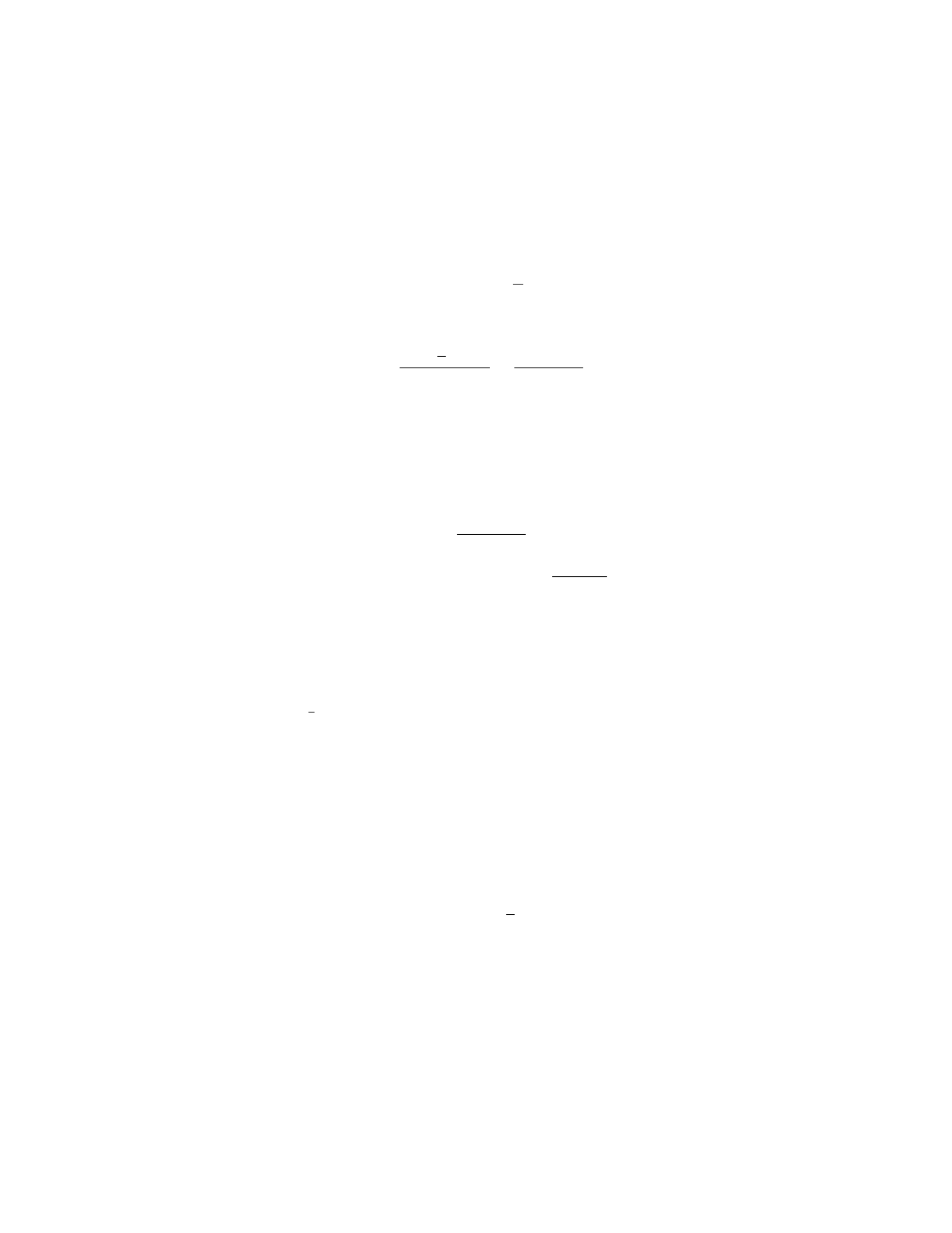
The torque due to the weight Mg about the pivot point is Mg ·L/2·cos θ(since
the perpendicular distance is L/2·cos θ), and it causes a clockwise rotation.
Step 3: Set up the equation for rotational equilibrium:
T·d·sin θ=Mg ·L
2·cos θ
Step 4: Solve for the tension at point C, T:
T=Mg ·L
2·cos θ
d·sin θ=MgL cos θ
2dsin θ
Step 5: Now, we want to express the distance xin terms of L,d, and θ.
From the geometry of the problem, we have:
x=d·cos θ
Step 6: Substitute x=d·cos θinto the expression for tension T:
T=MgL cos θ
2xsin θ
Therefore, the tension in the rod at point C is M gL cos θ
2xsin θ.
Question 31
Question
A uniform cylindrical log of wood with radius Rand length Lfloats vertically
in water with 1
4of its length above the water surface. What is the density of
the log? Assume the log is very long compared to its diameter.
Solution
Let’s denote the density of water as ρwand the density of the log as ρ. The
weight of the log is balanced by the upthrust or buoyancy force provided by the
water.
Step 1: Determine the weight of the log submerged in water.
The volume of the log submerged in water is equal to the volume of water
displaced. Using the formula for the volume of a cylinder, the volume of the log
submerged in water is given by V=πR2×L
4.
The weight of the log submerged in water is mg =ρV g, where mis the mass
of the log submerged, gis the acceleration due to gravity, and ρis the density
of the log.
Step 2: Determine the buoyant force acting on the log.
The buoyant force is given by Fb=ρwV g, where ρwis the density of water.
Step 3: Set up the equilibrium condition.
27

For the log to float in equilibrium, the weight of the log submerged in water
must be equal to the buoyant force acting on the log. Therefore, we have:
ρπR2L
4g=ρwπR2L
4g
Step 4: Solve for the density of the log.
Solving the equilibrium condition equation for ρ, we get:
ρ=ρw
Thus, the density of the log is equal to the density of water, ρw.
Question 32
Question
A 2.5 m long steel wire with a radius of 1.0 mm is stretched between two fixed
supports. If a 40 N weight is suspended from the wire, by how much does the
wire stretch? The Young’s modulus of steel is 2.0×10¹¹ N/m2.
Solution
Step 1: Find the cross-sectional area of the wire using the given radius. The
cross-sectional area of a wire is A=πr2, where ris the radius of the wire.
Substitute the radius r= 1.0 mm = 1.0×10⁻³m into the formula:
A=π(1.0×10⁻³)2
A=π×1.0×10⁻⁶
A= 3.14 ×10⁻⁶m2
Step 2: Calculate the tension in the wire due to the weight. The weight acts
downward, creating a tension in the wire equal in magnitude but opposite in
direction. We can calculate the tension Tusing the formula T=mg, where m
is the mass hanging on the wire and gis the acceleration due to gravity. Given
that m= 40 N and g= 9.81 m/s2:
T= 40 N ×9.81 m/s2
T= 392.4 N
Step 3: Determine the stress in the wire. Stress is defined as the ratio of
force to cross-sectional area. The formula for stress is S=T
A. Substitute the
values of Tand Ainto this formula:
S=392.4
3.14 ×10⁻⁶
28

S≈1.25 ×10⁸N/m2
Step 4: Calculate the strain in the wire using Hooke’s Law. Hooke’s Law
relates stress (S), Young’s modulus (Y), and strain (ε) in a material through
the equation S=Y ε. We can rearrange this formula to find the strain:
ε=S
Y
Substitute the values of Sand Yinto this formula:
ε=1.25 ×10⁸
2.0×10¹¹
ε= 0.000625
Step 5: Calculate the elongation of the wire. The elongation of the wire can
be calculated using the formula ∆L=εL, where ∆Lis the change in length, ε
is the strain, and Lis the original length of the wire. Given that L= 2.5 m:
∆L= 0.000625 ×2.5
∆L= 0.0015625 m = 1.5625 mm
Therefore, the wire stretches by approximately 1.5625 mm when the weight
is suspended from it.
Question 33
Question
A block of mass mis placed on an inclined plane with angle of inclination θ
above the horizontal. The coefficient of static friction between the block and
the plane is µs. What is the minimum angle at which the block will remain at
rest on the incline?
Solution
To find the minimum angle at which the block will remain at rest on the incline,
we need to consider the forces acting on the block. The forces involved are the
gravitational force (mg) acting vertically downward and the normal force (N)
acting perpendicular to the incline. Additionally, there is a frictional force (f)
opposing the motion along the incline.
Step 1: Draw a free-body diagram of the block to identify the forces.
The forces acting on the block are: - The gravitational force mg acting
vertically downward. - The normal force Nacting perpendicular to the incline.
- The frictional force facting parallel to the incline and opposite to the direction
of motion.
Step 2: Break down the gravitational force into components.
29

The component of the gravitational force parallel to the incline is mg sin θ.
The component of the gravitational force perpendicular to the incline is mg cos θ.
Step 3: Write the equations of equilibrium.
In the vertical direction:
N−mg cos θ= 0
N=mg cos θ
In the parallel direction:
f−mg sin θ= 0
f=mg sin θ
The maximum value for the frictional force fis µsN.
Step 4: Find the minimum angle at which the block will remain at rest.
For the block to remain at rest, the frictional force fmust be equal to or
greater than mg sin θ.
So, mg sin θ≤µsN=µsmg cos θ.
Solving for θ:
sin θ≤µscos θ
tan θ≤µs
Therefore, the minimum angle at which the block will remain at rest on the
incline is θ= arctan(µs).
Question 34
Question
A uniform beam of length Land mass Mis supported by a massless cable
attached to the midpoint of the beam, making an angle θwith the horizontal.
If the beam is in equilibrium, determine the tension in the cable.
beam_diagram.png
Solution
Step 1: To start, let’s draw the free-body diagram of the beam. The forces
acting on the beam are the tension in the cable (T) and the weight of the beam
acting at its center (M g
2). These forces create a counterclockwise torque which
is balanced by the torque due to the tension in the cable. Step 2: We can write
the torque equilibrium equation as:
Xτ= 0
30

TL
2sin(θ) = M g
2
L
2cos(θ)
Step 3: Now, we can simplify the equation:
Tsin(θ) = M g
4cos(θ)
Step 4: Since we are looking for the tension in the cable, we can solve for T:
T=Mg
4
cos(θ)
sin(θ)
T=Mg
4cot(θ)
Therefore, the tension in the cable is Mg
4cot(θ).
Question 35
Question
A spring with spring constant k= 200 N/m is compressed by a distance of 0.1 m.
The spring is then used to launch a 2 kg mass vertically upwards. Calculate the
maximum height the mass reaches above the launch point.
Solution
Step 1: Find the potential energy stored in the spring.
Potential energy stored in the spring = 1
2kx2
Where k= 200 N/m and x= 0.1 m.
P E =1
2×200 ×(0.1)2= 1 J
Step 2: Use the potential energy stored in the spring to calculate the initial
velocity of the mass.
Potential energy = Kinetic energy
P E =KE
P E =mgh =1
2mv2
h=v2
2g
1 = v2
2×9.8
31

Question 2
Question
A uniform wooden beam of length Land mass Mrests horizontally on two
supports, one at each end. A person weighing Wstands at a distance dfrom
one of the supports. Determine the magnitude and direction of the force exerted
by the support closer to the person.
Solution
Step 1: Begin by drawing a free-body diagram of the beam. Label the supports
as A and B, and the person as P, with forces
FA,
FB, and
Wacting on the
beam. The weight of the beam can be treated as acting at the center of mass,
resulting in a force
Fg=−Mgˆ
j.
Step 2: Write down the equilibrium conditions for the beam. Considering
the forces in both horizontal and vertical directions, we have:
XFx=0:FA=FB
XFy=0:FA+FB=Mg
Step 3: Now consider the torque equation about the support at A. The
torque due to the forces at B, P, and the beam’s weight all contribute:
τA=0=−FB
L
2+W d −Mg L
2
Step 4: Use the equations derived to solve for the value of the force FB
exerted by the support at B:
FB=W d
2L+Mg
2
Step 5: Substitute the expression for FBback into the equation PFx= 0,
to find the value of the force FAexerted by the support at A:
FA=W d
2L+Mg
2
Step 6: Therefore, the magnitude of the force exerted by the support closer
to the person is W d
2L+Mg
2, directed upwards.
Question 3
Question
A uniform rod of length Land mass Mis suspended horizontally from one end.
A weight of mass mis hung from the other end. If the rod has a density ρ, find
the force Frequired to keep the rod horizontal.
2

Solution
Step 1: Begin by identifying the forces acting on the rod. We have the force
of tension Tpulling upwards at the end where the weight is hung, the force of
gravity Mg acting downwards at the center of the rod, and the force Facting
horizontally at the end where the rod is suspended. Step 2: Calculate the
torque produced by the weight mabout the suspension point. The torque τ
due to the weight mis τ=mL
2g, where L
2is the distance from the suspension
point to the weight m. This torque causes a counterclockwise rotation. Step
3: Calculate the torque produced by the force Fabout the suspension point.
The torque τ′due to the force Fis τ′=F·L, where Lis the length of the
rod. This torque causes a clockwise rotation to balance the torque from the
weight m. Step 4: Set up the equilibrium condition for torques. For the rod
to be in equilibrium, the net torque acting on it must be zero. Thus, we have
τ−τ′= 0. Step 5: Substitute the expressions for τand τ′into the equilibrium
condition. We get mL
2g−F L = 0. Step 6: Solve for the force F. Rearranging
the equation, F=m·L·g
2. Therefore, the force Frequired to keep the rod
horizontal is F=m·L·g
2.
Question 4
Question
A uniform beam of length Land mass Mis supported by a pivot at one end
and a vertical wall at the other end. A weight of mass mis hung from a point
3L
4along the beam. Find the tension in the pivot and the force exerted by the
wall on the beam.
Solution
Step 1: Draw a free-body diagram of the beam.
Step 2: Write down the equilibrium condition in the vertical direction. The
sum of forces in the vertical direction must be zero.
T+N−Mg −mg = 0
Step 3: Write down the torque balance equation about the pivot point (point
A). The sum of torques about any point must be zero.
mg 3L
4−Mg(L) = 0
3

Step 4: Solve the system of equations.
(T+N=Mg +mg
mg 3L
4−Mg(L) = 0
Let’s denote Tas the tension in the pivot and Nas the force exerted by the
wall on the beam.
Step 5: Solve for Nin terms of Tfrom the first equation.
N=Mg +mg −T
Step 6: Substitute N=Mg +mg −Tinto the torque balance equation.
mg 3L
4−Mg(L) = 0
Step 7: Solve for Tby substituting N=Mg +mg −T.
mg 3L
4−Mg(L) = 0
mg 3L
4−Mg(L) = 0
T= 3mg −Mg
Therefore, the required tension in the pivot is 3mg −Mg and the force
exerted by the wall on the beam is Mg +mg −(3mg −Mg).
Question 5
Question
A uniform solid cylinder of mass Mand radius Ris held in place on a rough
horizontal surface by a horizontal force
Fapplied at a distance habove the
center of the cylinder (see Figure 1). The coefficient of static friction between
the cylinder and the surface is µs. Determine the minimum magnitude Fmin of
the force
Frequired to hold the cylinder in place.
cylinder_force.png
Solution
Step 1: We start by drawing a free-body diagram of the cylinder. The forces
acting on the cylinder are the gravitational force
Wdownward, the normal force
Nperpendicular to the surface, the static friction force
fspointing to the left,
and the external force
Fpointing to the right.
4

Step 2: We can see that the net force acting on the cylinder in the horizontal
direction must be zero for equilibrium:
F−fs= 0
Step 3: The friction force can have a maximum magnitude of µsN, where
Nis the magnitude of the normal force. In this case, Nmust balance the
gravitational force W. The normal force Ncan be calculated using the sum of
torques about the point of contact with the surface:
N=Mg
2+F h
Step 4: The friction force can now be expressed in terms of F:
fs=µsN=µsMg
2+F h
Step 5: Substituting this expression for fsinto the equation from Step 2
gives:
F−µsMg
2+F h= 0
Step 6: Solving for Fgives:
F=µsMg
2 + µsh
Therefore, the minimum magnitude Fmin of the force
Frequired to hold the
cylinder in place is µsMg
2+µsh.
Question 6
Question
A steel cable of length 10 m and diameter 2 cm is hung vertically from a fixed
support. A weight of 500 N is suspended from the bottom end of the cable.
Calculate the elongation of the cable due to the weight.
Solution
Step 1: Calculate the cross-sectional area of the steel cable using the formula
for the area of a circle: A=πr2, where ris the radius of the cable. Given
that the diameter of the cable is 2 cm, the radius ris 1 cm = 0.01 m. Thus,
A=π(0.01 m)2= 3.14 ×10⁻⁴m2.
Step 2: Calculate the stress on the cable using the formula: σ=F
A, where F
is the force applied to the cable. Given that the force Fis 500 N, and the cross-
sectional area Ais 3.14 ×10⁻⁴m2, we have: σ=500 N
3.14×10⁻⁴m2≈1.59 ×10⁶Pa.
5
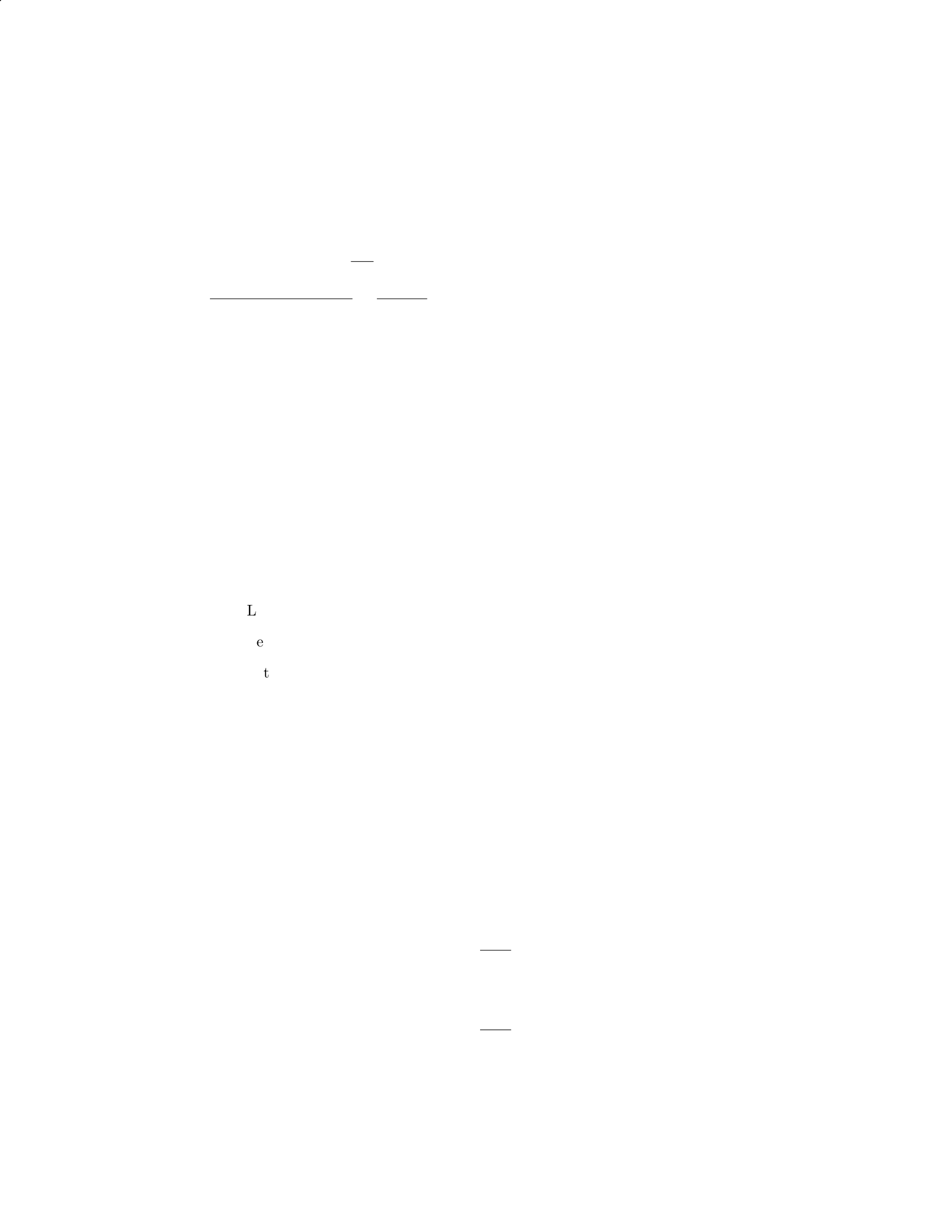
Step 3: Determine the Young’s modulus for steel, which is approximately
2×10¹¹ Pa.
Step 4: Calculate the elongation of the cable using the formula for linear
deformation: ∆L=F·L
A·E, where Lis the original length of the cable and Eis
the Young’s modulus for steel. Substitute the values into the formula: ∆L=
500 N×10 m
3.14×10⁻⁴m2×2×1011 Pa =5000
6.28×10⁷≈7.94 ×10⁻⁵m.
Therefore, the elongation of the cable due to the weight is approximately
7.94 ×10⁻⁵m or 0.0794 mm.
Question 7
Question
A uniform horizontal beam of length Land mass Mis attached to a vertical
wall by a hinge at one end and supported by a cable making an angle θwith
the beam. The other end of the cable is attached to the beam a distance xfrom
the hinge. Find the tension in the cable and the force exerted on the hinge.
Solution
Step 1: Draw a free-body diagram of the beam.
Let FHbe the horizontal force exerted on the beam by the hinge.
Let FTbe the tension in the cable.
Let Wbe the weight of the beam acting at its center.
Step 2: Write the torque equation about the hinge point.
FT·xsin θ= (L/2) ·W
Step 3: Write the force equation in the vertical direction.
FT·cos θ=W
Step 4: Write the force equation in the horizontal direction.
FH=FT·sin θ
Step 5: Solve for the tension FT.
FT=W
cos θ
Step 6: Substitute W=Mg and simplify.
FT=Mg
cos θ
6

Step 7: Solve for the horizontal force FH.
FH=Mg
cos θ·sin θ
Therefore, the tension in the cable is FT=M g
cos θand the force exerted on the
hinge is FH=Mg
cos θ·sin θ.
Question 8
Question
A uniform wooden beam of length Land mass Mis attached to a wall by a
hinge at one end, with a weight Whanging from the other end. The beam
makes an angle θwith the horizontal such that it is in equilibrium. The beam
has a moment of inertia Iabout its end where the weight is hanging. Determine
the tension in the hinge and the reaction force at the hinge.
Solution
Step 1: Draw a free-body diagram of the beam.
XFx=0:T−Rsin θ= 0
XFy=0:Rcos θ−W= 0
Step 2: Solve for Tand R. From the first equation:
T=Rsin θ
Substitute this expression into the second equation:
Rcos θ−W= 0
R=W
cos θ
Step 3: Calculate the moment of inertia I. The moment of inertia about the
end where the weight is hanging is given as I. For a beam of length Land mass
M, the moment of inertia about the end is 1
3ML2.
Step 4: Consider the torque equation about the hinge.
Xτ=Iα = 0
r×F=Iα
rT =I¨
θ
Lsin θ·R=1
3ML2¨
θ
7
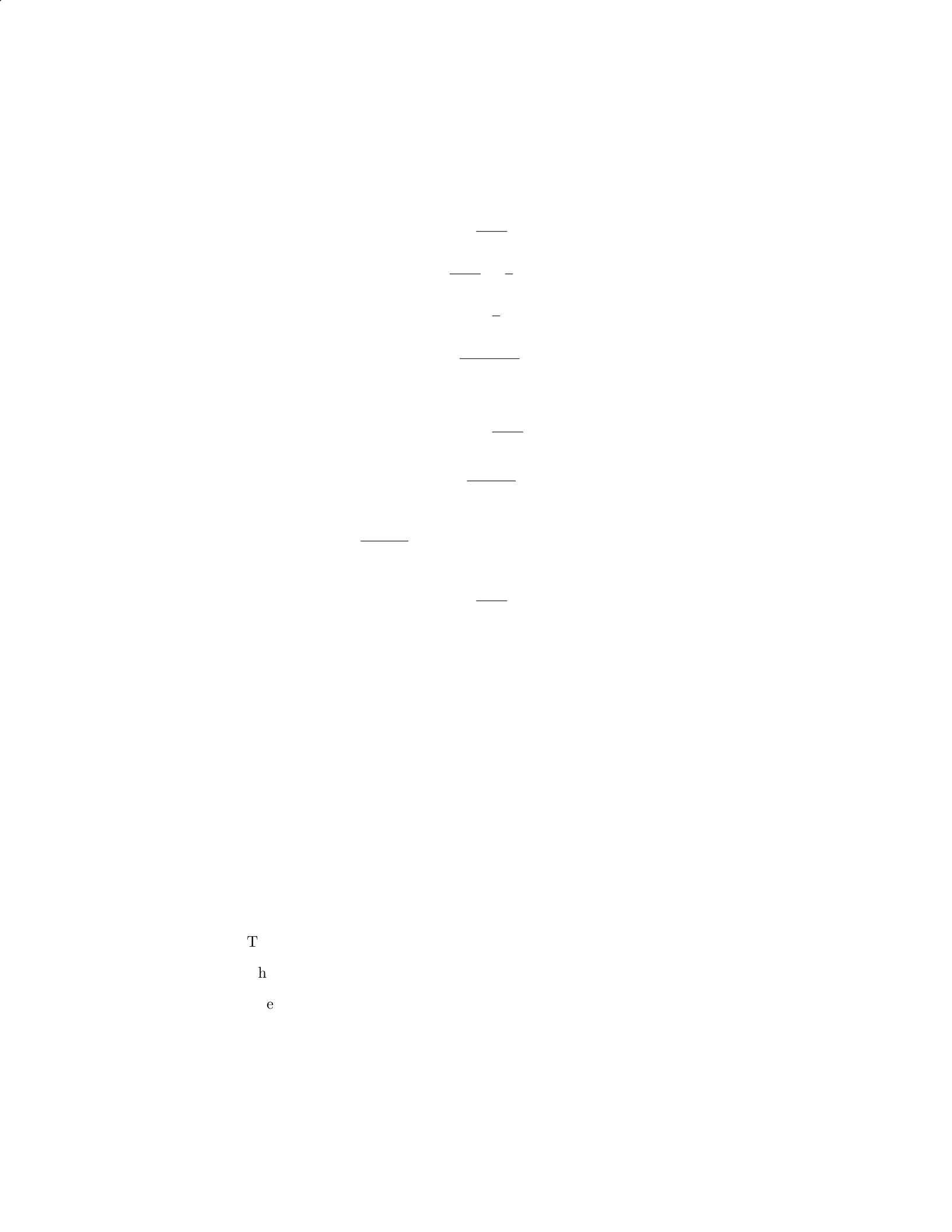
Step 5: Solve for ¨
θ.
R=W
cos θ
Lsin θ·W
cos θ=1
3ML2¨
θ
LW tan θ=1
3ML2¨
θ
¨
θ=3Wtan θ
L
Step 6: Calculate tension in the hinge.
T=Rsin θ=W
cos θsin θ
T=Wsin θ
cos θ
T=Wtan θ
Since we have ¨
θ=3Wtan θ
L, it means the tension in the hinge is T= 3W.
Step 7: Calculate the reaction force at the hinge.
R=W
cos θ
R=Wsec θ
Therefore, the tension in the hinge is 3Wand the reaction force at the hinge
is Wsec θ.
Question 9
Question
A block of mass mis placed on an inclined plane with an angle of elevation θ.
The block remains stationary with respect to the inclined plane. Determine the
coefficient of static friction µsbetween the block and the inclined plane.
Solution
Step 1: Draw a Free Body Diagram (FBD) of the block on the inclined plane.
The weight of the block mg acts downward.
The normal force Nacts perpendicular to the inclined plane.
The frictional force fsacts parallel to the inclined plane in the opposite
direction of motion.
8
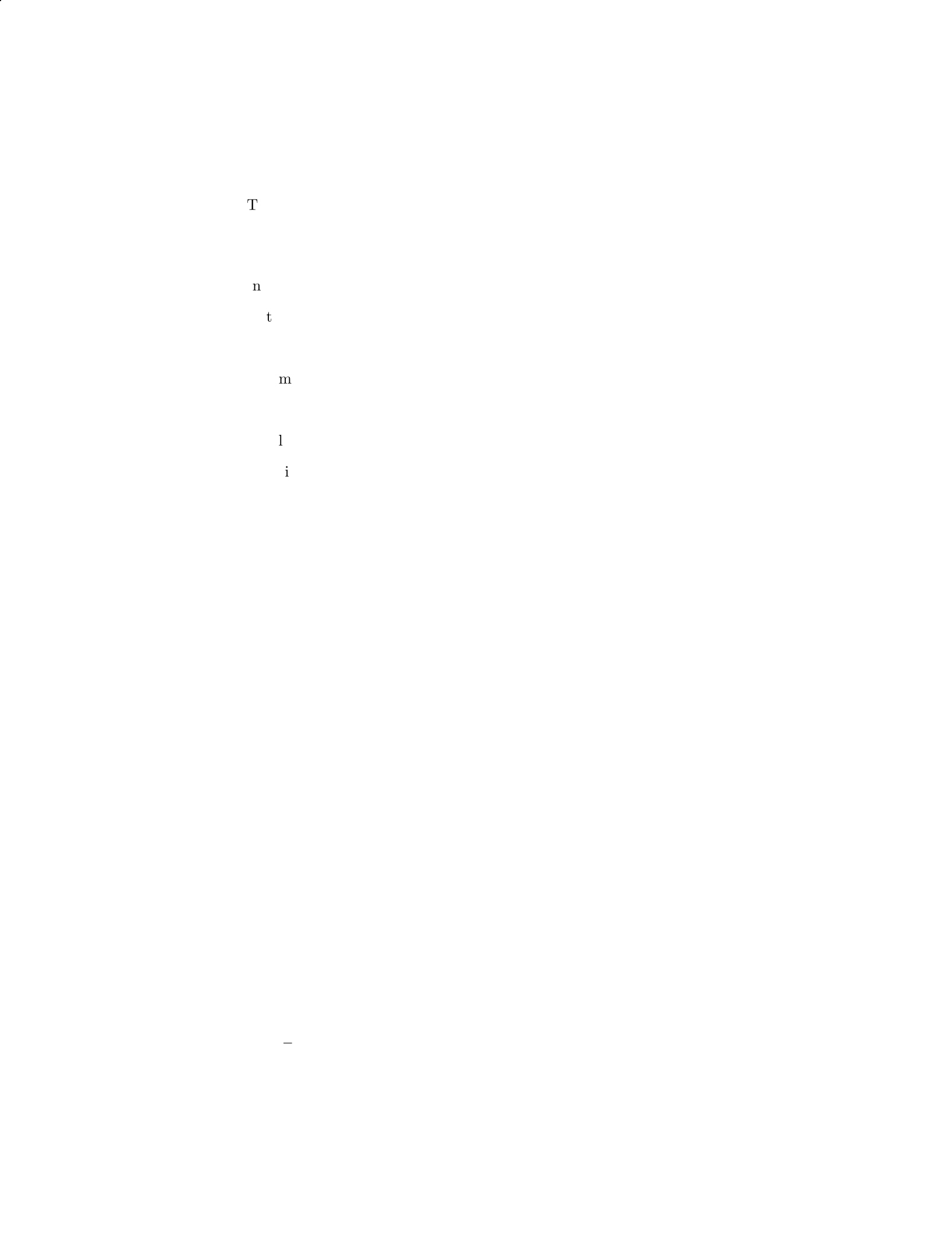
The component of the weight mg sin θacts parallel to the inclined plane
in the direction of motion.
Step 2: Write the force balance equations.
In the perpendicular direction: N=mg cos θ.
In the parallel direction: fs=mg sin θ.
Step 3: Determine the maximum value of static friction.
The maximum value of static friction is fmax =µsN=µsmg cos θ.
Step 4: Set up the equilibrium condition in the parallel direction.
Equilibrium condition: fmax =mg sin θ.
Substituting fmax =µsmg cos θand mg sin θinto the equilibrium condi-
tion gives µs= tan θ.
Therefore, the coefficient of static friction µsbetween the block and the
inclined plane is µs= tan θ.
Question 10
Question
A uniform beam of length Land mass Mis supported by a cable attached x
distance along the beam from one end. The beam makes an angle θwith the hor-
izontal. Given that the tension in the cable is Tand the beam is in equilibrium,
determine an expression for the distance xwhere the cable is attached.
Solution
Step 1: Draw a free body diagram of the forces acting on the beam.
XFy=T−Mg cos θ= 0
XFx=N−Mg sin θ= 0
Step 2: Solve for the normal force N. From the sum of the forces in the
x-direction, we have:
N=Mg sin θ
Step 3: Consider the torque about the end of the beam where the cable is
attached. The torque due to the weight of the beam about this point is given
by:
τ=Mgd sin θ
where d=L
2−x.
9

Step 4: Set up equilibrium condition for the torque. For the beam to be in
equilibrium, the sum of the torques must be zero:
τ= 0
T(x)−Mg(d) sin θ= 0
T(x) = Mg(L
2−x) sin θ
Step 5: Determine the expression for x. Since the beam is in equilibrium,
the tension in the cable is equal to the tension at the other end when pulling
the beam in the opposite direction:
T=Mg(L
2+x) sin θ
Mg(L
2−x) sin θ=Mg(L
2+x) sin θ
x=L
4
Therefore, the cable should be attached a distance x=L
4along the beam
from one end.
Question 11
Question
A uniform rod of length Land mass mis attached to a wall via a pivot at one
end. A force Fis applied perpendicular to the rod at a distance xfrom the
pivot. Find the magnitude and direction of the force required to keep the rod
in equilibrium.
Solution
To find the magnitude and direction of the force required to keep the rod in
equilibrium, we need to consider the torques acting on the rod and set them
equal to zero since the rod is not rotating.
Step 1: Identify the forces and torques. Let’s denote the pivot point
as O and the point of application of the force as P. The forces acting on the
rod are the gravitational force mg acting at the center of mass of the rod, the
normal force Nexerted by the pivot, and the applied force F. The torque due
to the normal force will be zero since its line of action passes through the pivot.
Step 2: Express the torques as a function of the variables. The
torque due to the gravitational force and the applied force are given by:
τgrav =−mg L
2sin θ
10
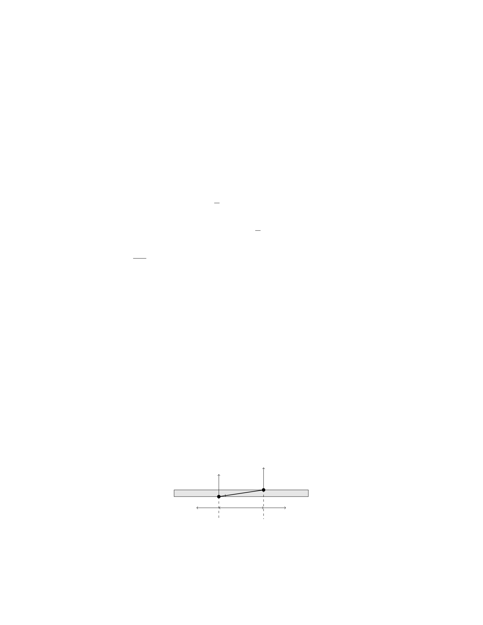
τF=F x sin θ
where θis the angle between the force and the rod.
Step 3: Set the total torque equal to zero. Since the rod is in equilib-
rium, the total torque about the pivot point O must be zero. Thus, we have:
τgrav +τF= 0
Step 4: Solve for the force F.Substitute the expressions for τgrav and
τFinto the equation and solve for F:
−mg L
2sin θ+F x sin θ= 0
F x =mg L
2
Therefore, the magnitude of the force required to keep the rod in equilibrium
is F=mgL
2x. The direction of the force will be perpendicular to the rod at a
distance xfrom the pivot.
Question 12
Question
A uniform beam of length Land mass Mis supported by two ropes attached
at points Aand Blocated at distances xand yfrom one end of the beam,
respectively. The tension in each rope is T. If the beam is in equilibrium and
the angle between the beam and the horizontal is θ, determine the tensions in
the ropes in terms of M,L,x,y, and θ.
Solution
Step 1: Draw a free-body diagram of the beam. Step 2: Write out the force
equilibrium equations in the xand ydirections. Step 3: Solve for the tensions
in the ropes in terms of M,L,x,y, and θ.
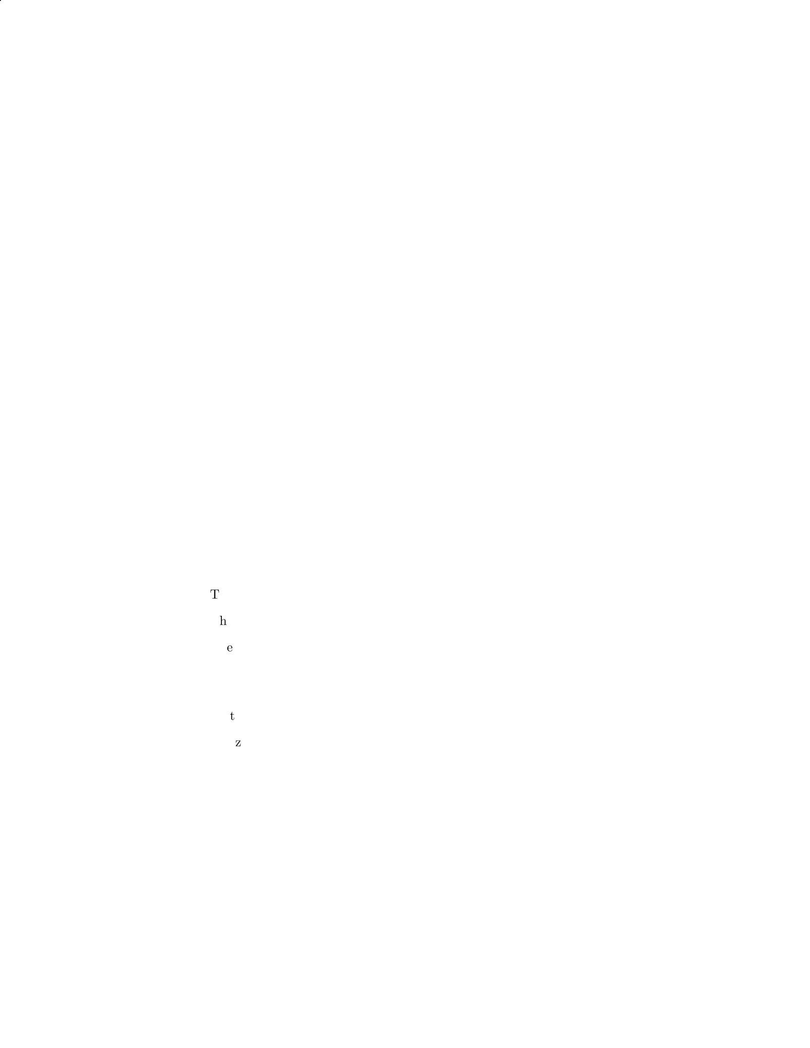
Step 1:
Let’s start by drawing a free-body diagram of the beam.
L
AB
T T
Mg Mg
θ
11
Step 2:
In the xdirection:
Tsin(θ)=0
In the ydirection:
2Tcos(θ)−2Mg = 0
Step 3:
From Tsin(θ) = 0, we find T= 0.
Then, substitute T= 0 into 2Tcos(θ)−2M g = 0 to find Mg = 0, which is
not possible for equilibrium.
Therefore, the only solution is T= 0, meaning the beam is not supported
by the ropes in equilibrium.
Question 13
Question
A uniform beam of length Land mass Mis supported by a vertical cable at a
distance dfrom one end. The beam makes an angle θwith the horizontal. Find
the tension in the cable.
Solution
Step 1: Draw a free-body diagram of the beam.
The weight Mg acts at the center of the beam downward.
The tension Tin the cable acts upward at an angle θto the vertical.
The normal force Nacts upward at the point of support.
Step 2: Write the equations of equilibrium in the vertical and horizontal
directions.
Vertical direction: N−Mg cos(θ)=0
Horizontal direction: T−Mg sin(θ)=0
Step 3: Solve the equations of equilibrium to find the tension in the cable.
From the vertical equilibrium equation, we can solve for the normal force: N=
Mg cos(θ).
Substitute the normal force into the horizontal equilibrium equation: T−
Mg sin(θ)=0
Therefore, T=Mg sin(θ).
So, the tension in the cable is T=Mg sin(θ).
12

Question 14
Question
A uniform beam of length Land mass Mis supported by a pivot at one end,
while the other end is connected to a cable that makes an angle θwith the
horizontal. The cable applies a tension force Tto the beam to keep it in equi-
librium. Find the tension in the cable and the reaction force at the pivot in
terms of M,L,g, and θ.
Solution
Step 1: Draw a free body diagram of the beam. There are two forces acting
on the beam: the tension force Tand the gravitational force Mg acting at the
center of mass of the beam.
Step 2: Resolve the forces into components. The tension force Tcan be
resolved into horizontal and vertical components: Tx=Tsin(θ) and Ty=
Tcos(θ).
Step 3: Write the equilibrium equations in the horizontal and vertical direc-
tions:
In the horizontal direction: Tx= 0
In the vertical direction: Ty−Mg = 0
Step 4: Solve the equations from Step 3 to find the tension Tand the reaction
force at the pivot:
From Tx= 0, we have Tsin(θ) = 0, which implies T= 0 (since sin(θ)= 0
for θ= 0).
From Ty−Mg = 0, we have Tcos(θ)−M g = 0, which implies T=M g
cos(θ).
Therefore, the tension in the cable is T=M g
cos(θ)and there is no reaction
force at the pivot since the tension force balances the gravitational force.
Question 15
Question
A uniform rod of length Land mass Mis placed horizontally on two supports.
A block of mass mis hung from a distance dof one end of the rod. If the rod
is on the verge of tipping, find the coefficient of static friction µsbetween the
rod and the supports.
Solution
1. Let’s begin by drawing a free-body diagram of the rod. The forces acting on
the rod are the gravitational force M g acting at the center of mass, the normal
forces N1and N2at the supports, the weight of the block mg acting downward
at a distance dfrom the left support, and the frictional force facting at the
right support.
13
2. Since the rod is on the verge of tipping, the sum of torques about the
left support must be zero. We can set up the equation for torque equilibrium
as follows:
f·L=mg ·d
f=m·g·d
L
3. To prevent the rod from tipping, the horizontal force at the supports
must provide a counter-clockwise torque that balances the clockwise torque due
to the block. This gives us the equation:
N1=N2+Mg
4. In the vertical direction, the net force must be zero:
N1+N2=Mg +mg
5. The maximum frictional force that can be applied is µsN1, since the rod
is just on the verge of tipping. Using the equations from steps 3 and 4, we can
express this maximum frictional force in terms of m,g, and d:
µsN1=µs(Mg +mg) = µs(g(M+m) = m·g·d
L
µs=m·g·d
Lg(M+m)=md
L(M+m)
So, the coefficient of static friction between the rod and the supports is
µs=md
L(M+m).
Question 16
Question
A long rod of length Land mass Mis pivoted at one end. A force Fis applied
at a distance xfrom the pivot point in a direction perpendicular to the rod.
Determine the force Fneeded to hold the rod in equilibrium, assuming the rod
is uniform and has a negligible mass compared to the force F.
Solution
To solve this problem, we will analyze the torques acting on the rod and set
them equal to zero since the rod is in equilibrium.
Step 1: Define the torque equation. The torque (τ) acting on the rod
due to the force Fis given by:
τ=F x
14
The torque due to the gravitational force acting at the center of mass of the
rod is:
τgravity =MgL
2
The torque due to the force of gravity acting at the distance xfrom the pivot
point is:
τgravity =Mgx
Step 2: Set up the equilibrium condition. For the rod to be in equi-
librium, the sum of the torques acting on it must be zero:
F x −Mgx −MgL
2= 0
Step 3: Solve for the force F.Substitute the expressions for the torques
into the equilibrium condition and solve for F:
F x −Mgx −MgL
2= 0
F x =Mgx +MgL
2
F=Mg +M
2
Thus, the force Fneeded to hold the rod in equilibrium is F=Mg +M
2.
Question 17
Question
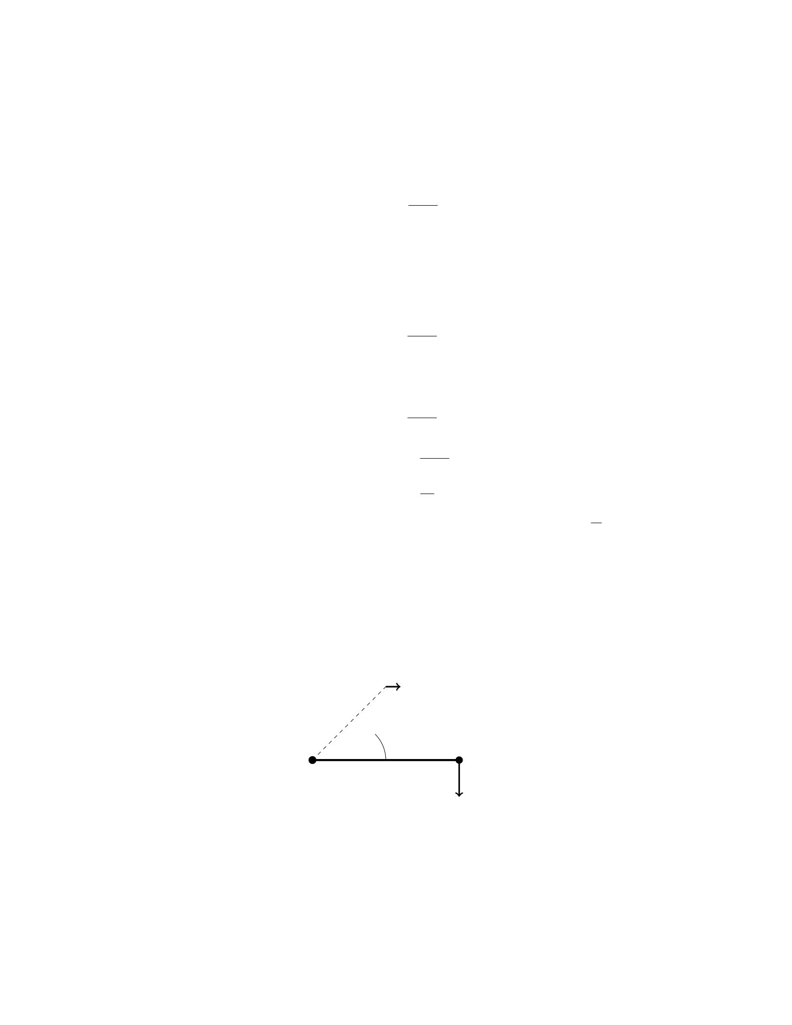
A uniform beam of length Land mass Mis supported by a cable attached to
one end of the beam, as shown in the figure below. The cable makes an angle θ
with the horizontal. What is the tension in the cable?
L
θ
T
W
15

Solution
Step 1: Find the forces acting on the beam. Since the beam is in equilibrium,
the sum of the forces in the horizontal and vertical directions must be zero. In
the vertical direction:
Tcos θ=Mg
In the horizontal direction:
Tsin θ= 0
Step 2: Solve for the tension in the cable. From the horizontal equilibrium
equation, we have:
Tsin θ= 0
T= 0
Therefore, the tension in the cable supporting the beam is zero.
Question 18
Question
A rigid rod of length Lis suspended horizontally from one end. A weight of
mass mis attached to the free end of the rod. The rod has a mass per unit
length λand a moment of inertia about its center of mass I. Determine the
tension at the point of attachment.
Solution
Step 1: We will first find an expression for the torque due to the weight of the
rod.
The torque due to the weight of the rod about the point of attachment is
given by τrod =1
2λLg. This can be obtained by integrating the weight of each
infinitesimal segment of the rod about the point of attachment and summing
the torques.
Step 2: Next, we will find an expression for the torque due to the weight
attached to the free end of the rod.
The torque due to the weight attached to the free end is τweight =mgL.
Step 3: We need to find the tension Tat the point of attachment. For
equilibrium, the sum of the torques about the point of attachment must be
zero.
Therefore, τrod +τweight −LT = 0.
Substitute the expressions for τrod and τweight into the equation above to
get:
1
2λLg +mgL −LT = 0.
Step 4: Solve for the tension T.
T=1
2λg +mg.
Hence, the tension at the point of attachment is T=1
2λg +mg.
16
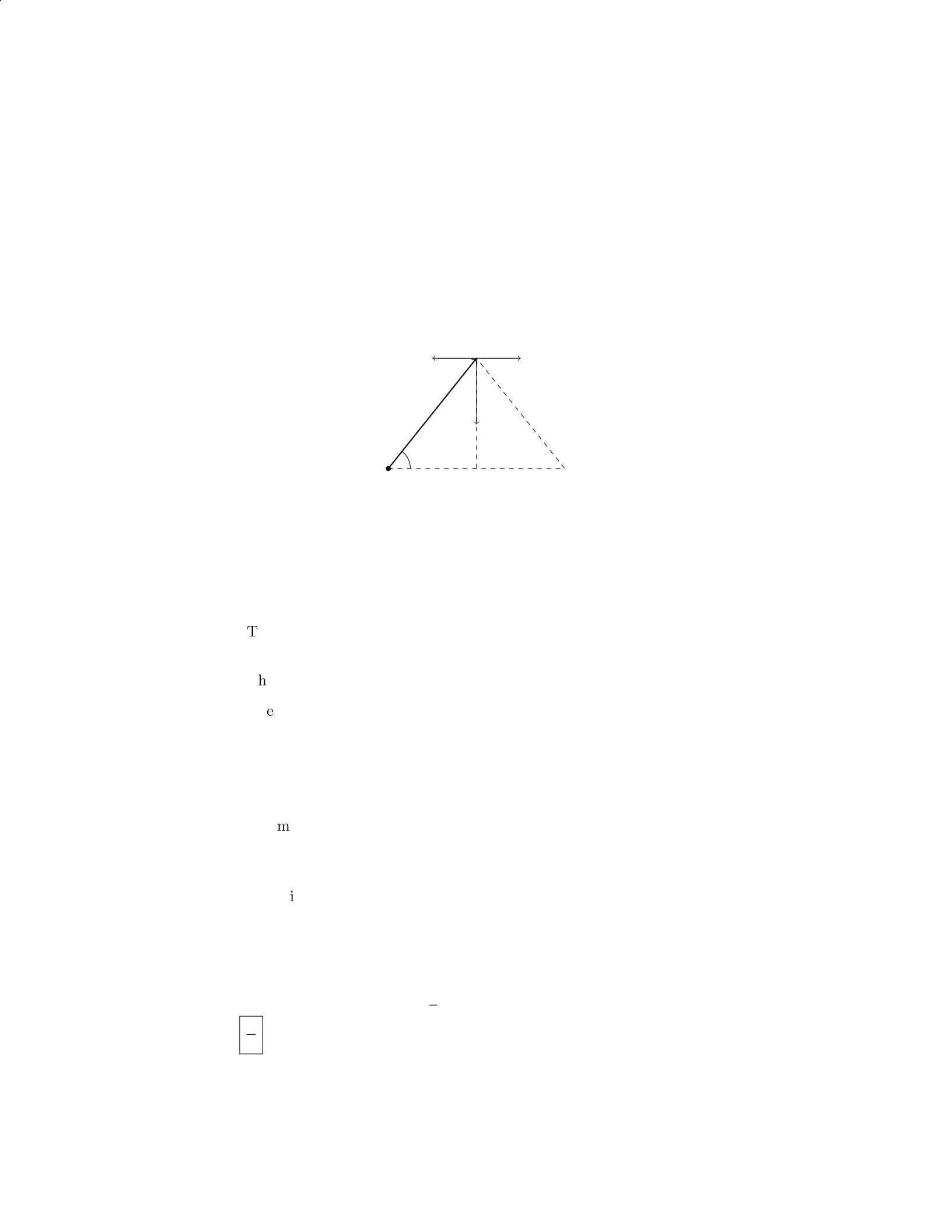
Question 19
Question
A uniform beam of length Land mass Mis supported by a cable attached at
its midpoint. The beam makes an angle θwith the horizontal, as shown in the
figure below:
L/2
Ft
Fg
T
θ
Given that the tension in the cable is Tand the force due to gravity is
Fg=Mg, determine the angle θin terms of T,M,g, and L. Assume that the
beam is in equilibrium.
Solution
Step 1: Decompose the forces acting on the beam.
The weight of the beam acts downward at the center, with a magnitude
of Fg=Mg.
The tension in the cable acts upward at an angle θfrom the horizontal.
The normal force from the beam’s support can be decomposed into hori-
zontal and vertical components. The force exerted by the support cancels
out the horizontal component of the tension, leaving only the vertical
component.
Step 2: Write out the force balance equations.
Summing forces in the vertical direction:
Tsin(θ) = Mg
Summing forces in the horizontal direction:
Tcos(θ)=0
Step 3: Solve for θ. From the horizontal force balance equation, Tcos(θ) = 0,
which gives T= 0 or cos(θ) = 0. Since Tcannot be zero for equilibrium, we
have cos(θ) = 0. Therefore, θ=π
2. Thus, the angle θin terms of T,M,g, and
Lis π
2.
17

Question 20
Question
A uniform beam of length Land mass Mis supported by two ropes attached at
its ends. A weight of Wis placed at a distance 2
3Lfrom one end of the beam.
If the tension in the rope at the end where the weight is placed is three times
the tension in the other rope, determine the value of W.
Solution
Step 1: Draw a free-body diagram of the beam. Let T1 and T2 be the tensions
in the ropes, and Rbe the reaction force at the support. Also, let xbe the
distance from the left end to the weight W.
Step 2: Write out the force equations along the y-direction. Summing the
forces in the vertical direction, we have:
T1 + T2 = Mg
Step 3: Write out the torque equation. The beam is in equilibrium, so the
sum of the torques about any point must be zero. Taking the point of rotation
at the left end, we have:
T1·2L
3−W·2L
3= 0
Step 4: Express T1 in terms of T2 and solve for W. Since we are given that
T1=3T2, we can substitute T1=3T2 into the torque equation:
3T2·2L
3−W·2L
3= 0
2T2−W
3= 0
W= 6T2
Step 5: Substitute back T1 + T2 = Mg and solve for W. Substitute T1 =
3T2 into T1 + T2 = Mg:
3T2 + T2 = Mg
4T2 = Mg
T2 = M g
4
Therefore, substituting T2 = M g
4into W= 6T2, we find:
W= 6 ×Mg
4=3Mg
2
So, the weight Wis 3
2times the weight of the beam Mg.
18

Question 21
Question
A uniform wooden beam of length Land mass Mis supported by two ropes
attached 1/3 and 2/3 of the way from one end. If the angle the ropes make with
the beam are θ1and θ2, respectively, find the tension in each rope.
Solution
Step 1: Draw the free body diagram of the beam.
Step 2: Resolve the forces into components.
Let T1be the tension in the rope making an angle θ1with the beam, and
T2be the tension in the rope making an angle θ2with the beam. The vertical
components of these forces balance the weight of the beam, and the horizontal
components balance each other due to equilibrium.
Step 3: Write the force equations.
For equilibrium in the vertical direction:
T1cos θ1+T2cos θ2=Mg
For equilibrium in the horizontal direction:
T1sin θ1=T2sin θ2
Step 4: Solve the force equations.
From the horizontal equilibrium equation, we have:
T1=T2
sin θ2
sin θ1
Substitute the expression for T1into the vertical equilibrium equation:
T2
sin θ2
sin θ1
cos θ1+T2cos θ2=Mg
Simplify the equation:
T2=Mg
sin θ2
sin θ1cos θ1+ cos θ2
Thus, the tension in each rope is T1=T2sin θ2
sin θ1and T2=Mg
sin θ2
sin θ1cos θ1+cos θ2
.
Question 22
Question
A uniform rectangular beam of length Land mass Mis supported by two
identical ropes attached to its ends. If the angle between the beam and each
rope is θ, find the tension in each rope.
19

Solution
Let’s denote the tension in each rope as T, the weight of the beam as W, and
the angle between the beam and each rope as θ. We will analyze the forces
acting on the beam in the vertical and horizontal directions.
Step 1: Analyzing forces in the vertical direction: The forces in the vertical
direction are the tension in each rope (2T) and the weight of the beam (W).
The weight can be expressed as W=Mg, where gis the acceleration due to
gravity.
XFy= 2Tcos θ−Mg = 0
2Tcos θ=Mg
T=Mg
2 cos θ
Step 2: Analyzing forces in the horizontal direction: Since the beam is in
equilibrium, there is no net force in the horizontal direction. Therefore, the
horizontal components of the tensions in the ropes balance each other.
XFx= 2Tsin θ= 0
Since the horizontal components of the tensions cancel each other out, there is
no acceleration in the horizontal direction.
Step 3: Final answer: The tension in each rope supporting the beam is
Mg
2 cos θ.
Question 23
Question
A uniform beam of mass Mand length Lis supported by a pivot at its center.
A block of mass mis placed on the left end of the beam. The beam is in
equilibrium with the block hanging vertically below the right end of the beam.
What is the mass of the beam if the tension in the string supporting the block
is equal to one-quarter the weight of the block?
Solution
1. To begin, let’s denote the mass of the uniform beam as Mand the mass of
the block as m. The center of mass of the beam is at L/2 from the pivot point.
2. We can start by writing down the equation for the torque about the pivot
point. Taking the counterclockwise direction as positive, we have:
Xτ= 0
3. The torque due to the block hanging on the right end of the beam is
given by mg L
2. Since the string supporting the block is at an angle, we can
20

break it into two components - one vertical and one horizontal component. The
vertical component provides the tension, and the horizontal component provides
no torque.
4. Given that the tension in the string supporting the block is equal to
one-quarter the weight of the block, we have T=1
4mg.
5. Now, we can write the equation for the torque about the pivot point:
T×L=mg L
2
6. Substituting T=1
4mg, we get:
1
4mg ×L=mg L
2
7. Solving for M, the mass of the beam, we get:
1
4mg =mg
2
8. Simplifying the equation and solving for M, we find:
M= 2m
Therefore, the mass of the beam is equal to twice the mass of the block.
Question 24
Question
A uniform beam of mass Mand length Lis supported by two cables attached
1/3 and 2/3 of the way along the beam. The beam is in equilibrium and the
tension in the shorter cable is T. Find the tension in the longer cable.
Solution
Step 1: Draw a free-body diagram of the beam with the forces acting on it.
Step 2: Label the distances from the left end of the beam to the two cables
xand L−x.
Step 3: Write out the torque equation for the beam about the left end,
taking counterclockwise as the positive direction:
Torqueshort cable + Torquelong cable = 0
Step 4: Calculate the torques: The torque due to the tension Tin the short
cable at a distance xfrom the left end is T(x−L
3). The torque due to the tension
in the long cable at a distance 2L/3−xfrom the left end is Tlong 2L
3−x.
21
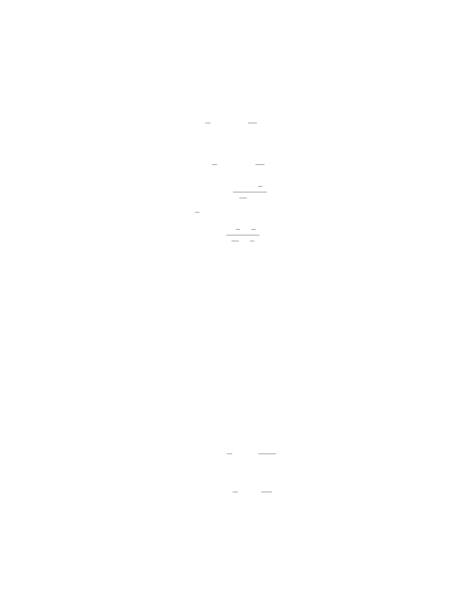
Step 5: Set up the torque equation:
T(x−L
3)−Tlong 2L
3−x= 0
Step 6: Simplify and solve for Tlong:
T(x−L
3) = Tlong 2L
3−x
Tlong =Tx−L
3
2L
3−x
Step 7: Substitute x=L
3and Tshort =Tinto the equation above:
Tlong =T(L
3−L
3)
2L
3−L
3
= 0
Therefore, the tension in the longer cable is zero.
Question 25
Question
A uniform horizontal beam of length Land mass Mis supported by a cable
attached at the midpoint of the beam. The other end of the cable is connected
to a wall. If the tension in the cable is T, find the force exerted by the wall on
the beam.
Solution
Let’s denote the force exerted by the wall on the beam as Fw. To solve this
problem, we will use the principle of torque equilibrium.
Step 1: Find the weight of the beam. The weight of the beam is given by
W=Mg, where Mis the mass of the beam and gis the acceleration due to
gravity.
Step 2: Analyze the torques acting on the beam. The torque due to the
weight of the beam about the point where the cable is attached is
τweight =L
2·W=MgL
2.
The torque due to the tension in the cable about the same point is
τtension =L
2·T=LT
2.
The torque due to the wall’s force is zero since the force is exerted at the
point about which we are taking torques.
22

Step 3: Set up the torque equilibrium equation. For the beam to be in
rotational equilibrium, the sum of the torques must be zero:
Xτ=τweight +τtension = 0.
Substitute in the known values:
MgL
2+LT
2= 0.
Step 4: Solve for the force exerted by the wall. From the torque equilibrium
equation, we can solve for Fw:
MgL
2=−LT
2,
Fw=Mg
2L−T
2.
Therefore, the force exerted by the wall on the beam is Fw=Mg
2L−T
2.
Question 26
Question
A cylindrical bronze rod with a diameter of 1.5 cm and length 2.0 m hangs
vertically from the ceiling. The Young’s modulus of bronze is 1.1×10¹¹ N/m2.
If the rod elongates by 1.5 mm under its own weight, determine the mass and
weight of the rod.
Solution
Step 1: Calculate the cross-sectional area of the rod. We have the diameter
d= 1.5 cm. The radius r=d/2 = 0.75 cm = 0.0075 m. The cross-sectional
area of a cylinder is given by A=πr2. Substituting the values we get,
A=π(0.0075)2
Step 2: Calculate the change in length of the rod. Given that the rod
elongates by 1.5 mm = 0.0015 m. The original length of the rod L= 2.0 m,
and the change in length ∆L= 0.0015 m
Step 3: Calculate the stress in the rod. Stress σis defined as force per unit
area and is given by:
σ=F
A
where Fis the force and Ais the cross-sectional area. The stress can also be
expressed in terms of the Young’s modulus Yand strain ϵas:
σ=Y ϵ
23

Step 4: Calculate the force acting on the rod. Using the formula σ=F
A, we
can solve for Fas:
F=σA
Step 5: Calculate the mass of the rod using the formula m=F
g, where gis
the acceleration due to gravity.
Step 6: Calculate the weight of the rod using the formula W=mg.
By following these steps, you can determine the mass and weight of the
bronze rod hung vertically from the ceiling.
Question 27
Question
A uniform ladder of length 5.0 m and weight 200 N leans against a smooth wall.
The ladder makes an angle of 30◦with the horizontal. Find the force exerted
by the wall and the magnitude of the contact force of the ground on the ladder.
Solution
Step 1: Draw a free-body diagram of the ladder.
Step 2: Resolve the forces into components. There are two forces acting
on the ladder: the force exerted by the wall (
Fwall) and the force exerted by
the ground (
Fground). The weight of the ladder can be split into two compo-
nents: one parallel to the ladder (mg sin θ) and one perpendicular to the ladder
(mg cos θ), where m= 20 kg is the mass of the ladder, g= 9.81 m/s2is the
acceleration due to gravity, and θ= 30◦.
Step 3: Write the equilibrium equations for the ladder in the xand ydirec-
tions.
For the xdirection:
Fwall = 0
For the ydirection:
Fground +mg cos θ= 0
Step 4: Solve the equilibrium equations to find Fwall and Fground.
From the ydirection equation:
Fground =−mg cos θ=−(20 kg)(9.81 m/s2) cos(30◦)≈ −169.15 N
Therefore, the magnitude of the contact force of the ground on the ladder is
approximately 169.15 N.
Step 5: Calculate the force exerted by the wall (Fwall).
Since the ladder is in equilibrium in the xdirection, we have Fwall = 0.
Thus, the force exerted by the wall on the ladder is 0 N.
24

Question 28
Question
A uniform beam of mass mand length Lis supported by a pivot at one end and
a wire attached 3L/4 from the pivot at the other end. The wire makes an angle
of 37 degrees with the vertical. Find the tension in the wire and the reaction at
the pivot.
Solution
Step 1: Draw a free-body diagram of the beam and identify the forces acting
on it. Let Tbe the tension in the wire, Rbe the reaction at the pivot, mg be
the gravitational force acting on the beam, and Nbe the normal force acting
on the beam. Step 2: Write out the equilibrium equations in the horizontal and
vertical directions. In the horizontal direction, the sum of the horizontal forces
is zero. In the vertical direction, the sum of the vertical forces is zero. Step 3:
Use trigonometry to express the components of the tension force. The horizon-
tal component of the tension force is Tsin(37◦) and the vertical component is
Tcos(37◦). Step 4: Write out the equations of equilibrium:
(Tsin(37◦)=0
R−mg =Tcos(37◦)
Step 5: Solve the system of equations to find the tension in the wire and the
reaction at the pivot. From the first equation, we get T= 0. Substituting T= 0
into the second equation gives R=mg. Step 6: Therefore, the tension in the
wire is 0 and the reaction at the pivot is mg.
Question 29
Question
A steel wire of length 2.0 m and diameter 2.0 mm is stretched by a force of 500
N. If the density of steel is 7.8×10³kg/m3and the Young’s modulus of steel is
2×10¹¹ N/m2, find the change in length of the wire. Assume it remains elastic.
Solution
Step 1: Calculate the cross-sectional area of the wire.
Given that the diameter of the wire is 2.0 mm, the radius is 2.0 mm/2 =
1.0 mm = 1.0×10⁻³m. The cross-sectional area Aof the wire is:
A=πr2=π(1.0×10⁻³m)2
25

Step 2: Calculate the stress on the wire.
The stress σon the wire is given by:
σ=F
A
Substitute F= 500 N and the calculated Ainto the equation.
Step 3: Calculate the strain in the wire.
The Young’s modulus Yrelates stress and strain through the formula:
Y=σ
ε
Solve for ε:
ε=σ
Y
Step 4: Calculate the change in length of the wire.
The strain εis related to the change in length ∆Lby:
ε=∆L
L
Solve for ∆L:
∆L=ε·L
Now, substitute the calculated stress σ, Young’s modulus Y, and length
L= 2.0 m into the above equations to find the change in length ∆L.
Question 30
Question
A uniform rod of length Land mass Mis supported by a pivot point located
a distance dfrom one end of the rod. The rod is at equilibrium when it makes
an angle θwith the horizontal. What is the tension in the rod at point C, a
distance xfrom the pivot point, in terms of L,M,d,x, and θ?
Solution
Step 1: Draw a free-body diagram of the rod when it is at equilibrium. Consider
the forces acting on the rod: the tension at point C(label it as T), the weight
acting at the center of mass (label it as M g downward), and the reaction force
at the pivot point (label it as Rupward). The angles between the forces and
the rod are θ,θ, and 90◦, respectively.
Step 2: Apply the condition for rotational equilibrium, which states that
the sum of the torques acting on the rod about the pivot point must be zero.
The torque due to the tension Tabout the pivot point is T·d·sin θ(since the
perpendicular distance is d·sin θ), and it causes a counterclockwise rotation.
26
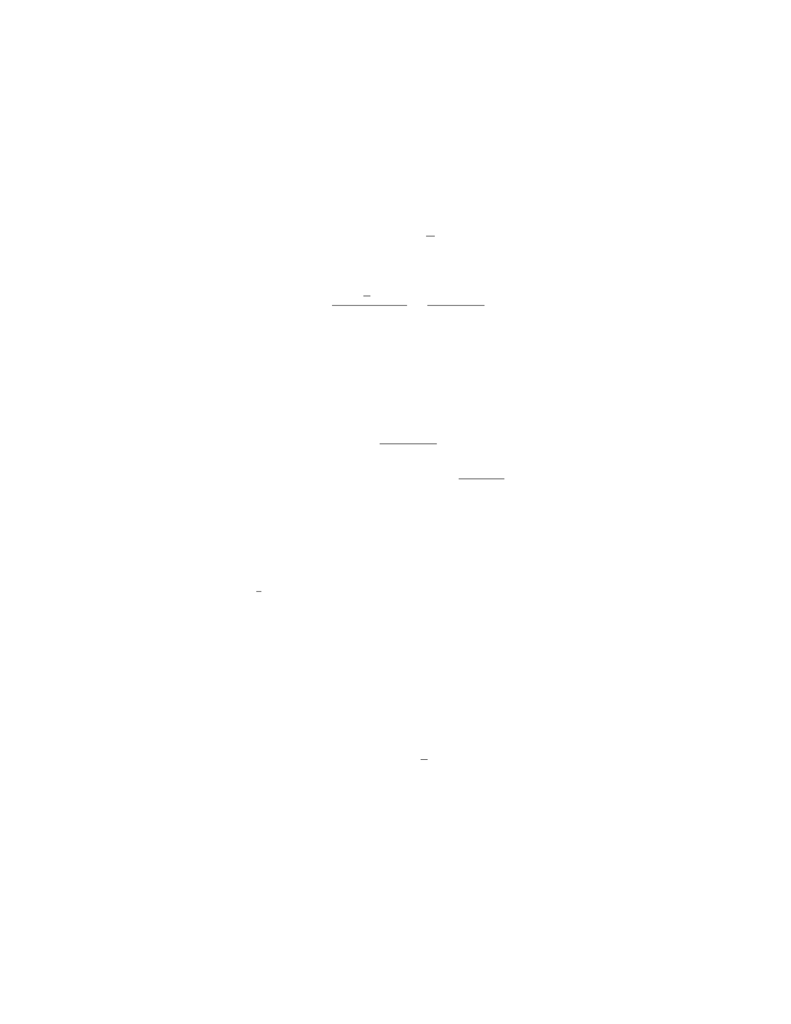
The torque due to the weight Mg about the pivot point is Mg ·L/2·cos θ(since
the perpendicular distance is L/2·cos θ), and it causes a clockwise rotation.
Step 3: Set up the equation for rotational equilibrium:
T·d·sin θ=Mg ·L
2·cos θ
Step 4: Solve for the tension at point C, T:
T=Mg ·L
2·cos θ
d·sin θ=MgL cos θ
2dsin θ
Step 5: Now, we want to express the distance xin terms of L,d, and θ.
From the geometry of the problem, we have:
x=d·cos θ
Step 6: Substitute x=d·cos θinto the expression for tension T:
T=MgL cos θ
2xsin θ
Therefore, the tension in the rod at point C is M gL cos θ
2xsin θ.
Question 31
Question
A uniform cylindrical log of wood with radius Rand length Lfloats vertically
in water with 1
4of its length above the water surface. What is the density of
the log? Assume the log is very long compared to its diameter.
Solution
Let’s denote the density of water as ρwand the density of the log as ρ. The
weight of the log is balanced by the upthrust or buoyancy force provided by the
water.
Step 1: Determine the weight of the log submerged in water.
The volume of the log submerged in water is equal to the volume of water
displaced. Using the formula for the volume of a cylinder, the volume of the log
submerged in water is given by V=πR2×L
4.
The weight of the log submerged in water is mg =ρV g, where mis the mass
of the log submerged, gis the acceleration due to gravity, and ρis the density
of the log.
Step 2: Determine the buoyant force acting on the log.
The buoyant force is given by Fb=ρwV g, where ρwis the density of water.
Step 3: Set up the equilibrium condition.
27

For the log to float in equilibrium, the weight of the log submerged in water
must be equal to the buoyant force acting on the log. Therefore, we have:
ρπR2L
4g=ρwπR2L
4g
Step 4: Solve for the density of the log.
Solving the equilibrium condition equation for ρ, we get:
ρ=ρw
Thus, the density of the log is equal to the density of water, ρw.
Question 32
Question
A 2.5 m long steel wire with a radius of 1.0 mm is stretched between two fixed
supports. If a 40 N weight is suspended from the wire, by how much does the
wire stretch? The Young’s modulus of steel is 2.0×10¹¹ N/m2.
Solution
Step 1: Find the cross-sectional area of the wire using the given radius. The
cross-sectional area of a wire is A=πr2, where ris the radius of the wire.
Substitute the radius r= 1.0 mm = 1.0×10⁻³m into the formula:
A=π(1.0×10⁻³)2
A=π×1.0×10⁻⁶
A= 3.14 ×10⁻⁶m2
Step 2: Calculate the tension in the wire due to the weight. The weight acts
downward, creating a tension in the wire equal in magnitude but opposite in
direction. We can calculate the tension Tusing the formula T=mg, where m
is the mass hanging on the wire and gis the acceleration due to gravity. Given
that m= 40 N and g= 9.81 m/s2:
T= 40 N ×9.81 m/s2
T= 392.4 N
Step 3: Determine the stress in the wire. Stress is defined as the ratio of
force to cross-sectional area. The formula for stress is S=T
A. Substitute the
values of Tand Ainto this formula:
S=392.4
3.14 ×10⁻⁶
28

S≈1.25 ×10⁸N/m2
Step 4: Calculate the strain in the wire using Hooke’s Law. Hooke’s Law
relates stress (S), Young’s modulus (Y), and strain (ε) in a material through
the equation S=Y ε. We can rearrange this formula to find the strain:
ε=S
Y
Substitute the values of Sand Yinto this formula:
ε=1.25 ×10⁸
2.0×10¹¹
ε= 0.000625
Step 5: Calculate the elongation of the wire. The elongation of the wire can
be calculated using the formula ∆L=εL, where ∆Lis the change in length, ε
is the strain, and Lis the original length of the wire. Given that L= 2.5 m:
∆L= 0.000625 ×2.5
∆L= 0.0015625 m = 1.5625 mm
Therefore, the wire stretches by approximately 1.5625 mm when the weight
is suspended from it.
Question 33
Question
A block of mass mis placed on an inclined plane with angle of inclination θ
above the horizontal. The coefficient of static friction between the block and
the plane is µs. What is the minimum angle at which the block will remain at
rest on the incline?
Solution
To find the minimum angle at which the block will remain at rest on the incline,
we need to consider the forces acting on the block. The forces involved are the
gravitational force (mg) acting vertically downward and the normal force (N)
acting perpendicular to the incline. Additionally, there is a frictional force (f)
opposing the motion along the incline.
Step 1: Draw a free-body diagram of the block to identify the forces.
The forces acting on the block are: - The gravitational force mg acting
vertically downward. - The normal force Nacting perpendicular to the incline.
- The frictional force facting parallel to the incline and opposite to the direction
of motion.
Step 2: Break down the gravitational force into components.
29

The component of the gravitational force parallel to the incline is mg sin θ.
The component of the gravitational force perpendicular to the incline is mg cos θ.
Step 3: Write the equations of equilibrium.
In the vertical direction:
N−mg cos θ= 0
N=mg cos θ
In the parallel direction:
f−mg sin θ= 0
f=mg sin θ
The maximum value for the frictional force fis µsN.
Step 4: Find the minimum angle at which the block will remain at rest.
For the block to remain at rest, the frictional force fmust be equal to or
greater than mg sin θ.
So, mg sin θ≤µsN=µsmg cos θ.
Solving for θ:
sin θ≤µscos θ
tan θ≤µs
Therefore, the minimum angle at which the block will remain at rest on the
incline is θ= arctan(µs).
Question 34
Question
A uniform beam of length Land mass Mis supported by a massless cable
attached to the midpoint of the beam, making an angle θwith the horizontal.
If the beam is in equilibrium, determine the tension in the cable.
beam_diagram.png
Solution
Step 1: To start, let’s draw the free-body diagram of the beam. The forces
acting on the beam are the tension in the cable (T) and the weight of the beam
acting at its center (M g
2). These forces create a counterclockwise torque which
is balanced by the torque due to the tension in the cable. Step 2: We can write
the torque equilibrium equation as:
Xτ= 0
30

TL
2sin(θ) = M g
2
L
2cos(θ)
Step 3: Now, we can simplify the equation:
Tsin(θ) = M g
4cos(θ)
Step 4: Since we are looking for the tension in the cable, we can solve for T:
T=Mg
4
cos(θ)
sin(θ)
T=Mg
4cot(θ)
Therefore, the tension in the cable is Mg
4cot(θ).
Question 35
Question
A spring with spring constant k= 200 N/m is compressed by a distance of 0.1 m.
The spring is then used to launch a 2 kg mass vertically upwards. Calculate the
maximum height the mass reaches above the launch point.
Solution
Step 1: Find the potential energy stored in the spring.
Potential energy stored in the spring = 1
2kx2
Where k= 200 N/m and x= 0.1 m.
P E =1
2×200 ×(0.1)2= 1 J
Step 2: Use the potential energy stored in the spring to calculate the initial
velocity of the mass.
Potential energy = Kinetic energy
P E =KE
P E =mgh =1
2mv2
h=v2
2g
1 = v2
2×9.8
31

v=√19.6≈4.4 m/s
Step 3: Use the initial velocity to find the maximum height. At the maximum
height, the vertical velocity will be 0 m/s.
v2=u2+ 2as
0 = (4.4)2−2×9.8×h
h=(4.4)2
2×9.8≈0.97 m
Therefore, the maximum height the mass reaches above the launch point is
approximately 0.97 m.
32

