


PHYS 231 - UNIVERSITY PHYSICS I
- Equilibrium and Elasticity
Question Bank - Set 10
Liberty University
Question 1
Question
A uniform rod of length Land mass Mis resting against a vertical wall. The
coefficient of static friction between the rod and the wall is µs. Calculate the
minimum angle θat which the rod can be supported without slipping.
Solution
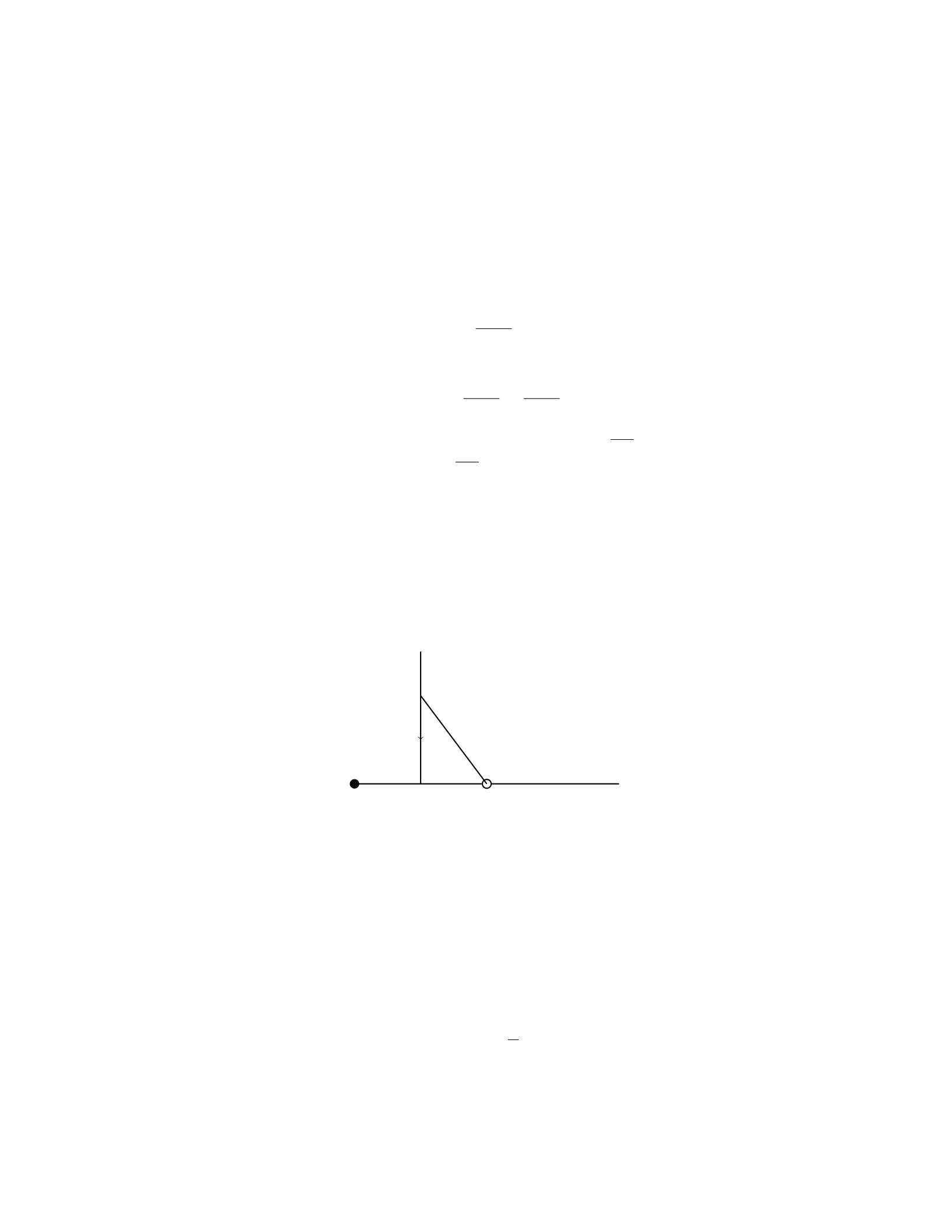
Step 1: First, draw a free-body diagram of the forces acting on the rod. Here,
we have the weight W=Mg acting downward at the center of the rod, the
normal force Nacting perpendicular to the wall at the point of contact, and
the frictional force fsacting upward along the wall.
Step 2: Resolve the weight Winto components parallel and perpendicular to
the wall. The component parallel to the wall is W∥=Wsin θand the component
perpendicular to the wall is W⊥=Wcos θ.
Step 3: Write out the equilibrium condition in the direction perpendicular
to the wall. The sum of forces in the y-direction must be zero:
N−W⊥= 0
N−Mg cos θ= 0
N=Mg cos θ
Step 4: Write out the equilibrium condition in the direction parallel to the
wall. The sum of forces in the x-direction must be zero:
fs−W∥= 0
fs−Mg sin θ= 0
fs=Mg sin θ
Step 5: The maximum static frictional force that the wall can exert is
fs,max =µsN. Substituting N=Mg cos θ:
µsMg cos θ=Mg sin θ
Step 6: Solve for θto find the minimum angle at which the rod can be
supported without slipping:
µscos θ= sin θ
tan θ=µs
θ= tan−1(µs)
Question 2
Question
A uniform bar of length Land mass Mis supported horizontally at its ends
by two vertical cables. The bar is pierced by a pivot at a distance xfrom one
end. A weight Wis attached to the bar at a distance yfrom the pivot on the
opposite side. Find the tension in each cable in terms of M,L,W,x, and y
when the system is in equilibrium.
Solution
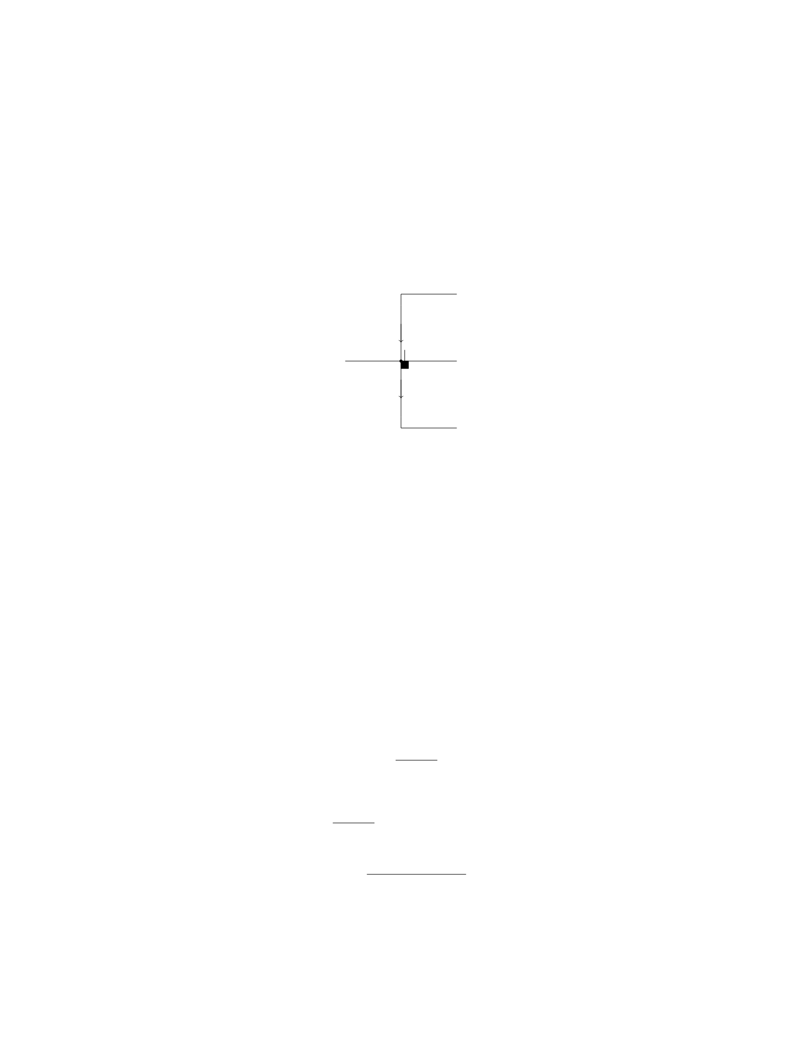
Step 1: Draw a free-body diagram of the bar.
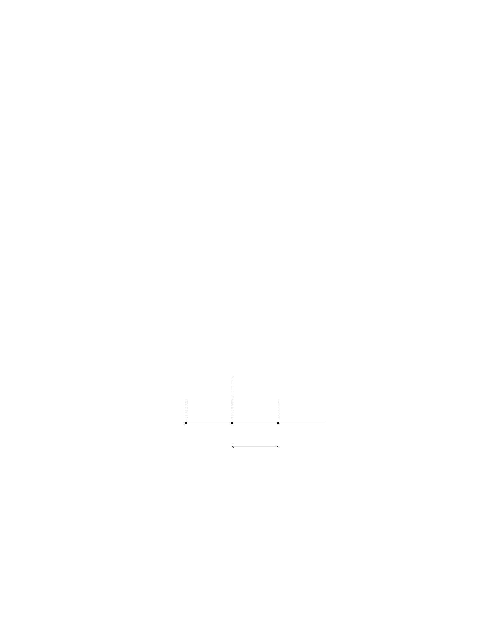
xL
W
T2
T1
y
Step 2: Write out the equations for equilibrium in both the horizontal and
vertical directions. In the vertical direction, we have:
T1+T2−W= 0
In the horizontal direction, we have:
T2y−T1x= 0
2
Step 3: Solve the system of equations to find T1and T2. From the vertical
equilibrium equation, we have T1+T2=W. Solving for T1, we get T1=W−T2.
Substitute this into the horizontal equilibrium equation:
(T2)y−(W−T2)x= 0
Solving for T2gives:
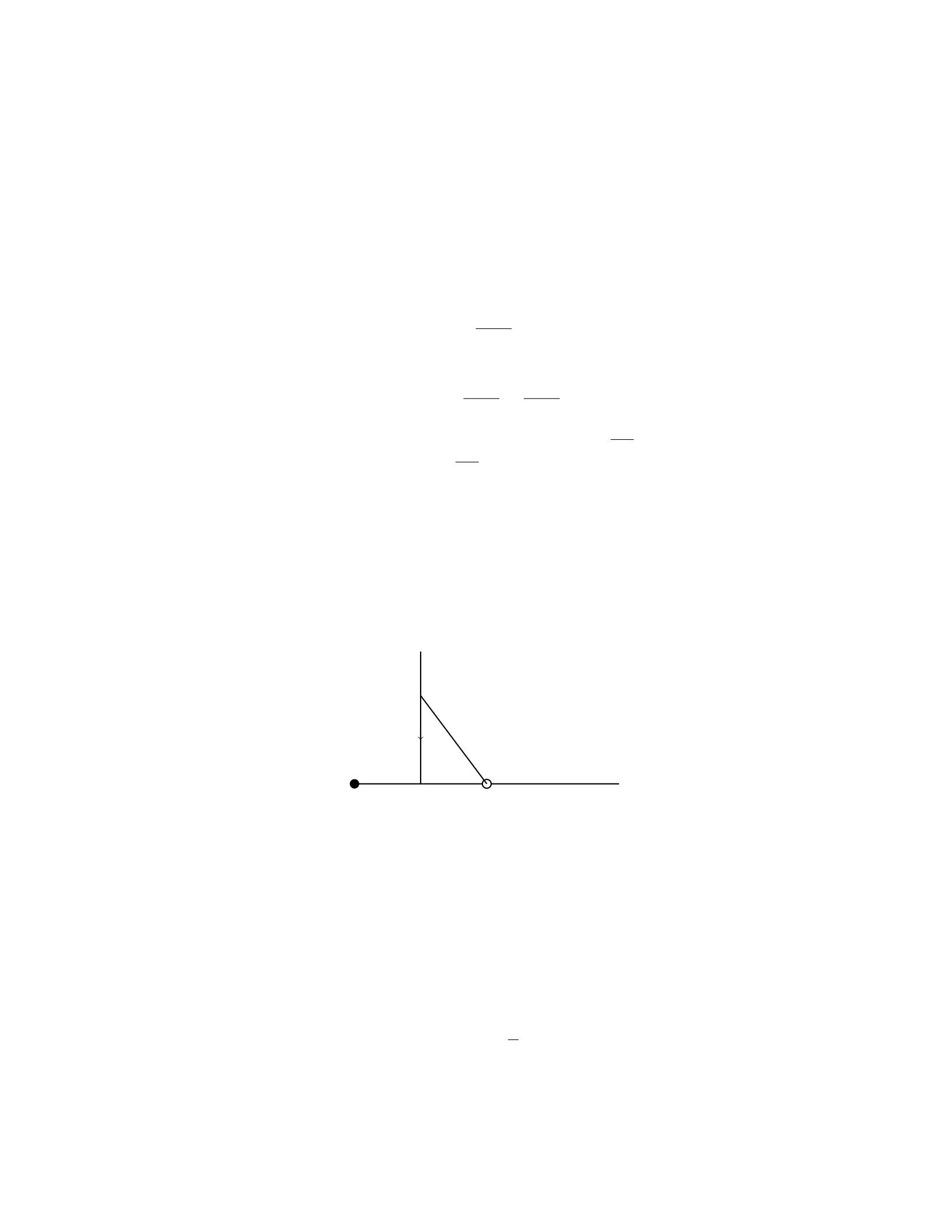
T2=W x
x+y
Substitute T2back into the vertical equilibrium equation to find T1:
T1=W−W x
x+y=W y
x+y
Therefore, the tension in the cable at the left end (T1) is W y
x+yand the tension
in the cable at the right end (T2) is W x
x+y.
Question 3
Question
A uniform beam of length Land mass Mis supported by a pivot at its midpoint.
A block of mass mis suspended at the left end of the beam by a rope. The
block is initially at rest at a distance xfrom the pivot as shown in the diagram
below.
Pivot
x
L/2
h
F
m
Determine the tension in the rope as a function of x,L,m,M,g, and h.
Assume the beam is in equilibrium.
Solution
Step 1: The torques about the pivot point must sum to zero in order for the
beam to be in rotational equilibrium. The torque due to the mass mis equal
to mgx, and the torque due to the beam’s center of mass (located at L/2) must
also be considered. Since the beam is uniform, its weight can be modeled as
acting at its center of mass, which creates a torque of MgL/2. Therefore, the
torque equation is:
mgx =Mg L
2
3

Step 2: Solving for xin the equation above, we find:
x=ML
2m
Step 3: To find the tension in the rope, we need to consider the forces
acting on the block m. The vertical forces must sum to zero since the block is
stationary. Therefore, the tension in the rope Tis equal to the weight of the
block:
T=mg
Step 4: Substituting mwith Mand xwith ML
2min the equation above, we
find the tension in the rope as a function of x,L,m,M, and g:
T=Mg 1−M
2m
Question 4
Question
A uniform beam of length Land mass Mis supported by a pivot at its midpoint.
A weight Wis attached to the right end of the beam. Determine the tension in
the beam at a distance xfrom the pivot point due to the weight W.
Solution
Step 1: Draw a Free Body Diagram (FBD) of the beam.
The force of gravity acting on the beam can be represented as Mg
2acting
at the midpoint of the beam.
The tension force in the beam at a distance xfrom the pivot point can be
represented as T.
The weight Wat the right end of the beam also acts downwards.
Step 2: Write out the equilibrium equations.
For translational equilibrium in the vertical direction: PFy= 0
T+Mg
2+W= 0
For rotational equilibrium: Pτ= 0 (using pivot as the point of rotation)
T·x−W·L= 0
Step 3: Solve the equilibrium equations simultaneously.
4

From the translational equilibrium equation, we find: T=−Mg
2−W
Substituting this into the rotational equilibrium equation, we get: (−Mg
2−
W)·x−W·L= 0
−Mgx
2−W x −W L = 0
W=−Mgx
2L−W x
L
Therefore, the tension in the beam at a distance xfrom the pivot point due
to the weight Wis −Mgx
2L−W x
L.
Question 5
Question
A uniform rod of length Land mass Mis hinged at one end and supported
horizontally at the other end by a vertical rope. The rod makes an angle θ
with the vertical. Find the tension in the rope and the horizontal and vertical
components of the force exerted by the hinge on the rod in terms of L,M,θ,
and g.
Solution
Step 1: Draw a free body diagram of the rod. Let the tension in the rope be
T, the horizontal component of the force exerted by the hinge be H, and the
vertical component of the force exerted by the hinge be V. The weight of the
rod acts at the center of mass (L
2) and is given by Mg. The forces acting on
the rod are the tension Tand the forces exerted by the hinge at the fixed end.
Step 2: Write the equilibrium equations. In the horizontal direction:
H=Tsin θ
In the vertical direction:
V=Mg −Tcos θ
Taking moments about the hinge:
Tcos θ·L
2=H·L
Step 3: Solve the system of equations. Substitute the expression for Hfrom
the first equilibrium equation into the moment equation:
Tcos θ·L
2=Tsin θ·L
Tcos θ·1
2=Tsin θ
5

2 sin θ= cos θ
Solving for θ:
tan θ=2
1
θ= tan−1(2)
Now, substitute θback into the equilibrium equations to solve for T,H, and
V.
Question 6
Question
A uniform rod of length 2Land mass Mis supported by a pivot at the center
of the rod. A block of mass mis placed at a distance dfrom the left end of the
rod. Determine the condition under which the system is in equilibrium.
Solution
To find the condition under which the system is in equilibrium, we need to
consider the torques acting on the rod and the block.
Step 1: Set up the coordinate system
Let’s place the origin at the pivot point, O, and define the positive x-direction
to the right. The forces acting on the system are the weight of the rod and the
weight of the block as well as the normal force from the pivot.
Step 2: Write the torque equilibrium equation
The condition for rotational equilibrium is that the net torque acting on the
system is zero. Let’s sum the torques about the pivot point, O. The torque due
to the normal force at Ois zero since it acts at the pivot point. The torques due
to the weight of the rod and the weight of the block must balance each other
out.
The torque due to the weight of the rod about the pivot point is L
2·Mg
(acting in the clockwise direction). The torque due to the weight of the block
about the pivot point is d·mg (acting in the counterclockwise direction).
Setting the total torque equal to zero, we have:
L
2Mg −dmg = 0
Step 3: Solve for the condition for equilibrium
Solving for d, we get:
d=L
2
Therefore, the system will be in equilibrium when the block is placed at a
distance of L
2from the left end of the rod.
6
Question 7
Question
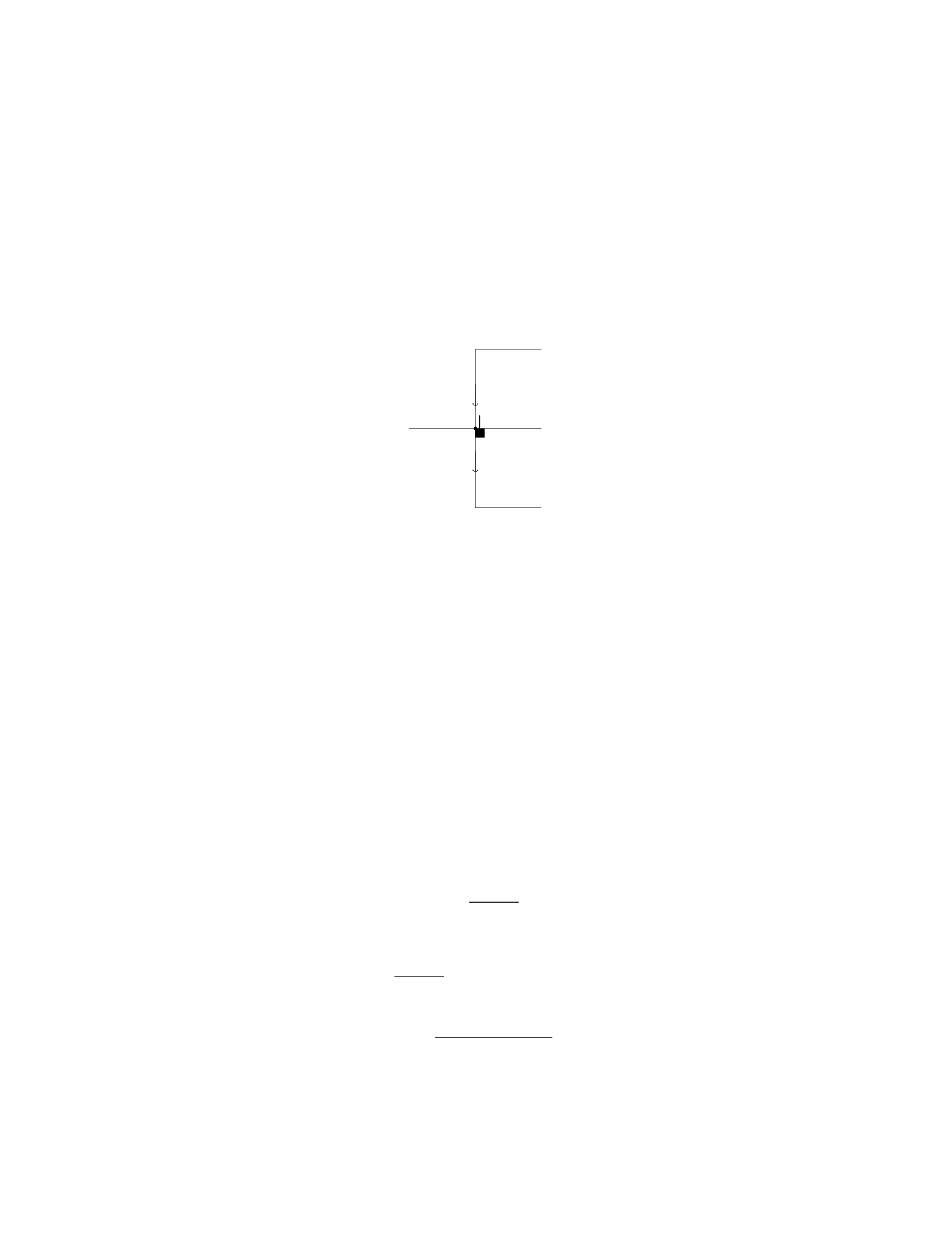
A uniform rod of length Land mass Mis supported horizontally by two vertical
strings, as shown in the figure below. The left string makes an angle θwith the
vertical and the right string makes an angle ϕwith the vertical. Calculate the
tension in each string.
L/2
T1
T2
θ
ϕ
Assume θ > ϕ.
Solution
Step 1: Identify the forces acting on the rod.
The forces acting on the rod are: - The weight mg acting downward at the
center of the rod. - The tension T1from the left string acting at an angle θwith
the vertical. - The tension T2from the right string acting at an angle ϕwith
the vertical.
Step 2: Write out the force equations in the horizontal and vertical directions.
In the vertical direction:
T1cos θ+T2cos ϕ=mg
In the horizontal direction:
T1sin θ=T2sin ϕ
Step 3: Solve the force equations for the tensions T1and T2.
From the horizontal force equation, we have:
T1=T2sin ϕ
sin θ
Substitute T1into the vertical force equation:
T2sin ϕ
tan θ+T2cos ϕ=mg
Solve for T2:
T2=mg tan θ
sin ϕ+ cos ϕtan θ
7

Step 4: Substitute T2back into the expression for T1.
T1=mg tan θsin ϕ
sin θ(sin ϕ+ cos ϕtan θ)
Therefore, the tension in each string is:
T1=mg tan θsin ϕ
sin θ(sin ϕ+ cos ϕtan θ)
T2=mg tan θ
sin ϕ+ cos ϕtan θ
Question 8
Question
A uniform bar of length Land mass Mis suspended horizontally by two vertical
strings attached to its ends. A weight Wis attached at a distance xfrom one
end of the bar. Determine the tension in each string.
Solution
Step 1: Draw a free-body diagram of the bar. Let T1and T2be the tensions in
the strings attached to the ends of the bar, and Wbe the weight attached at
a distance xfrom the left end of the bar. The forces acting on the bar are: 1.
The tension T1acting to the left. 2. The tension T2acting to the right. 3. The
weight Wacting downwards. 4. The weight of the bar acting downwards at its
center of mass.
Step 2: Write the equations of equilibrium. In the horizontal direction, the
sum of forces is zero:
T1=T2(horizontal equilibrium)
In the vertical direction, the sum of forces is zero:
T1+T2=W+Mg (vertical equilibrium)
Step 3: Express Wand the tensions in terms of Mand L. The weight Wcan
be expressed as W=Mg +Mgx/L. Substitute W,T1=T2into the equation
T1+T2=W+Mg:
2T1=Mg +Mgx/L +M g
Step 4: Solve for the tension in each string. Solving for T1:
2T1=Mg(1 + x/L)
T1=Mg(1 + x/L)
2
Therefore, the tension in each string is T1=Mg(1+x/L)
2and T2=Mg(1+x/L)
2.
8

Question 9
Question
A uniform beam of length Land mass Mis supported by a hinge at one end
and a rope attached at a distance L
4from the hinge. A person of mass mstands
at the other end of the beam. What is the tension in the rope when the beam
is on the verge of tipping?
Solution
Let’s denote the lengths of the two segments of the beam as xand L−x, where
xis the distance from the hinge to the person.
Step 1: Free body diagrams We will draw two separate free body dia-
grams (FBDs) for the beam and the person. For the beam: The forces acting on
the beam are its weight Mg acting at the center of mass (which is at a distance
L/2 from the hinge), the tension Tin the rope, and the normal force at the
hinge. For the person: The forces acting on the person are their weight mg and
the normal force at the end of the beam.
Step 2: Writing Equations of Equilibrium For the beam: In the hori-
zontal direction: 0 = TIn the vertical direction: T=Mg. For the person: In
the vertical direction: N−mg = 0 where Nis the normal force acting on the
person.
Step 3: Torque Equation For the beam to be on the verge of tipping, the
net torque about the hinge point has to be zero. The torque from the weight of
the beam is L
2Mg in the clockwise direction. The torque from the weight of the
person is (L−x)mg also in the clockwise direction. The torque from the tension
in the rope is 3L
4Tin the counterclockwise direction. Setting these equal to get
the equation for equilibrium:
L
2Mg −(L−x)mg −3L
4T= 0
Step 4: Solve for Tension From the torque equation, we have:
L
2Mg −(L−x)mg −3L
4T= 0
Solving for T:L
2Mg −(L−x)mg =3L
4T
T=2
3L
2Mg −(L−x)mg
Therefore, the tension in the rope when the beam is on the verge of tipping
is 2
3L
2Mg −(L−x)mg
9

Question 10
Question
A constant force of 75 N is applied horizontally to a block on a rough surface.
The block has a mass of 5 kg. The coefficient of kinetic friction between the
block and the surface is 0.3. Determine the acceleration of the block.
Solution
Step 1: Identify the forces acting on the block. The forces acting on the block
are: - The applied force, Fapplied = 75 N. - The weight of the block, W=mg,
where m= 5 kg and g= 9.81 m/s2. - The frictional force, ffriction =µk·N,
where µk= 0.3 is the coefficient of kinetic friction and Nis the normal force.
Step 2: Find the normal force. Since the block is on a horizontal surface
and not accelerating vertically, the normal force Nis equal to the weight of the
block:
N=mg = 5 kg ×9.81 m/s2= 49.05 N
Step 3: Calculate the frictional force.
ffriction =µk·N= 0.3×49.05 N = 14.715 N
Step 4: Determine the net force acting on the block. The net force Fnet is
given by:
Fnet =Fapplied −ffriction = 75 N −14.715 N = 60.285 N
Step 5: Calculate the acceleration of the block. Using Newton’s second law
(Fnet =ma), we can find the acceleration a:
60.285 N = 5 kg ×a
a=60.285 N
5 kg = 12.057 m/s2
Therefore, the acceleration of the block is 12.057 m/s2.
Question 11
Question
A steel cable with a cross-sectional area of 4.0×10⁻⁴m2is suspended vertically
from a support. The cable has a mass of 100 kg. Determine the elongation
of the cable when a 400 kg mass is attached to the bottom of the cable. The
Young’s modulus for steel is 2.0×10¹¹ N/m2.
10

Solution
Step 1: Calculate the force of gravity on the steel cable: The force of gravity
acting on the steel cable is the combined weight of the cable itself and the 400
kg mass attached to it:
Fcable =mcable ·g+mattached ·g
where mcable = 100 kg, mattached = 400 kg, and g= 9.81 m/s2.
Fcable = (100 kg + 400 kg) ·9.81 m/s2
Fcable = 500 kg ·9.81 m/s2
Fcable = 4905 N
Step 2: Calculate the stress on the steel cable: The stress σon the cable is
given by:
σ=F
A
where F= 4905 N is the force acting on the cable and A= 4.0×10⁻⁴m2is
the cross-sectional area of the cable.
σ=4905 N
4.0×10⁻⁴m2
σ= 1.22625 ×10⁷N/m2
Step 3: Calculate the strain on the steel cable: The strain εon the cable is
given by:
ε=σ
Y
where Y= 2.0×10¹¹ N/m2is the Young’s modulus for steel.
ε=1.22625 ×10⁷N/m2
2.0×10¹¹ N/m2
ε= 6.13125 ×10⁻⁵
Step 4: Calculate the elongation of the steel cable: The elongation ∆Lof
the cable is given by:
∆L=ε·L
where Lis the original length of the cable. Since the cable is vertical, the
elongation is along the length of the cable.
∆L= 6.13125 ×10⁻⁵·L
Step 5: Substitute the values and solve for ∆L: The original length of the
cable Lis not given in the question. However, based on the assumptions in this
problem, we can consider the cable to be very long compared to its elongation
when the attached weight is added. Therefore, the elongation of the cable when
the 400 kg mass is attached to it is approximately:
∆L≈6.13125 ×10⁻⁵·L
11

Question 12
Question
A uniform beam of length Land mass Mis supported horizontally by a cable
attached at the end of the beam. The angle between the beam and the horizontal
is θ. Find the tension Tin the cable.
Solution
Step 1: We will start by drawing a free body diagram of the beam. There are
three forces acting on the beam: the gravitational force Mg acting at the center
of the beam, the tension force Tacting at an angle θto the horizontal, and the
normal force Nacting vertically upwards.
Step 2: Since the beam is in equilibrium, the sum of the forces in the x-
direction and y-direction must be zero. Therefore, we can write two equations:
(Tsin(θ) = N
Tcos(θ) = Mg
Step 3: Next, we need to consider the torque equation. Taking torques about
the end of the beam where the cable is attached, we have:
Xτ= 0 =⇒T L sin(θ) = L
2·Mg
Step 4: Solving the torque equation for T, we get:
T=Mg
2 sin(θ)
Therefore, the tension in the cable is Mg
2 sin(θ).
Question 13
Question
A steel cable of length 10 m and cross-sectional area 0.001 m2is suspended
vertically. A 2000 kg mass is attached to the bottom of the cable. If the
Young’s modulus of steel is 2 ×10¹¹ N/m2, determine the elongation of the
cable.
Solution
Step 1: Find the weight of the mass. The weight of an object can be calculated
using the formula
Fgravity =mg,
12

where mis the mass and gis the acceleration due to gravity.
Given that m= 2000 kg and g= 9.8 m/s2, we have
Fgravity = (2000 kg)(9.8 m/s2) = 19600 N.
Step 2: Use Hooke’s Law to find the elongation. Hooke’s Law relates the
force applied to a spring/cable to its elastic properties. It states that the force
required to stretch/ compress a spring/cable by a distance xis directly propor-
tional to x. The equation for Hooke’s Law is
F=kx,
where Fis the force applied, kis the spring constant (in this case, the Young’s
modulus), and xis the elongation.
Step 3: Calculate the elongation of the cable. The force applied to the
cable is equal to the weight of the mass, i.e., F= 19600 N. Therefore, we can
determine the elongation using Hooke’s Law as
19600 = (2 ×10¹¹)(A)L
x,
where Ais the cross-sectional area of the cable, Lis the original length of the
cable, and xis the elongation we are solving for. Plugging in the values gives
19600 = (2 ×10¹¹)(0.001) 10
x.
Step 4: Solve for xto find the elongation. Solving for xgives
x=(2 ×10¹¹)(0.001)(10)
19600 ≈0.01 m.
Therefore, the elongation of the steel cable is approximately 0.01 m.
Question 14
Question
A wooden block of mass 2 kg is hanging vertically on a horizontal rod attached
to a wall. The block is held in equilibrium by a force of 50 N acting at an
angle of 30 degrees to the horizontal. Calculate the tension in the rod and the
horizontal force exerted by the wall on the block.
Solution
Step 1: Break down the forces acting on the block into components. Let T
be the tension in the rod, Fwall be the horizontal force exerted by the wall,
Fexternal be the external force applied, and Wbe the weight of the block. The
13

forces acting on the block can be resolved into components as follows: Fext,x =
Fexternal = 50 cos(30◦) to the right
Fext,y = 0 (vertical equilibrium)
Tx=−Tto the left
Ty=Tupwards
Wx= 0
Wy=−mg downwards, where m= 2 kg and g= 9.8 m/s2.
Step 2: Write down the equilibrium equations in the x and y directions. In
the x-direction: Fext,x +Fwall +Tx= 0
50 cos(30◦) + Fwall −T= 0
In the y-direction: Ty+Wy= 0
T−mg = 0
Step 3: Solve the equilibrium equations. From the y-direction equation, we
have T=mg = 2 ×9.8 = 19.6 N.
Substitute Tback into the x-direction equation: 50 cos(30◦)+Fwall−19.6=0
Fwall = 19.6−50 cos(30◦)
Fwall ≈4.04 N
Therefore, the tension in the rod is 19.6 N and the horizontal force exerted
by the wall on the block is approximately 4.04 N.
Question 15
Question
A uniform rod of length Land mass Mis initially at rest on a frictionless
horizontal surface. A force Fis then applied at a distance xfrom one end of
the rod, perpendicular to the rod and parallel to the surface. The rod will begin
to rotate around its center of mass once the force exceeds a certain magnitude.
Find the minimum magnitude Fmin of the force Fthat will cause the rod to
rotate.
Solution
1. We start by analyzing the forces acting on the rod. There are two forces
acting on the rod: the force Fapplied at distance xfrom the center of mass
of the rod and the gravitational force acting on the center of mass of the rod.
Since the rod is in equilibrium, the sum of the torques about any point must be
zero.
2. The torque due to the force Fabout the center of the rod is given by
τF=F·x, where xis the distance from the applied force to the center of mass
of the rod. The torque due to the gravitational force at the center of the rod is
zero since the force acts through the center of mass.
3. In order for the rod to start rotating around its center of mass, the net
torque about the center of mass must be non-zero. Therefore, we have:
τnet =τF>0
14

4. Setting τF>0, we have:
F·x > 0
5. Since xis a positive distance from the center of the rod, for τFto be
positive, Fmust also be positive.
6. Therefore, the minimum magnitude of the force Fthat will cause the rod
to rotate is given by:
Fmin = 0
Hence, the minimum magnitude Fmin of the force Fthat will cause the rod
to rotate is zero.
Question 16
Question
A uniform rod of length Land mass Mis initially at rest on a frictionless
horizontal surface. A small mass mis dropped from a height habove the
midpoint of the rod and lands on it without bouncing. Find the angular velocity
of the rod just after the mass lands on it.
Solution
Step 1: Initially, the system is at rest, so the total initial angular momentum is
zero.
Step 2: When the mass mlands on the rod, the system will start to rotate.
This will conserve angular momentum.
Step 3: The final moment of inertia of the system can be calculated as
follows:
Irod =1
12M L2
Imass =1
3mL
22
=1
12mL2
Itotal =Irod +Imass =1
12M L2+1
12mL2=1
6ML2
Step 4: The final angular momentum of the system can be expressed as:
Lfinal =Itotalω
where ωis the final angular velocity.
Step 5: The initial angular momentum is zero and the final angular momen-
tum is given by the angular momentum of the falling mass:
Lfalling mass =mL
2v=mL
2p2gh
15

Step 6: Setting the initial and final angular momenta equal to each other
and solving for ωgives:
mL
2p2gh =1
6ML2ω
ω=3m
ML p2gh
Therefore, the angular velocity of the rod just after the mass lands on it is
3m
ML √2gh.
Question 17
Question
A block of mass m= 5 kg is placed on an inclined plane with an angle of
inclination θ= 30◦. The coefficient of static friction between the block and the
plane is µs= 0.4. Determine the minimum force Fparallel to the incline that
must be applied to the block to prevent it from sliding down the plane.
Solution
Step 1: Draw a free-body diagram of the block.
Step 2: Identify the forces acting on the block. These forces include the
force of gravity mg acting downwards, the normal force Nacting perpendicular
to the plane, the force of static friction ffriction acting up the incline to prevent
sliding, and the force Fparallel to the incline.
Step 3: Resolve the forces into components parallel and perpendicular to
the incline. The force of gravity mg can be resolved into mg sin θparallel to the
incline and mg cos θperpendicular to the incline.
Step 4: Write the equilibrium equations. The sum of forces in the perpen-
dicular direction should be zero, N=mg cos θ. The sum of forces in the parallel
direction should also be zero, F−ffriction −mg sin θ= 0.
Step 5: Determine the maximum force of static friction that can act on the
block before it starts to slide. ffriction =µsN=µsmg cos θ.
Step 6: Substitute N=mg cos θand ffriction =µsmg cos θinto the equation
F−ffriction −mg sin θ= 0 to find the minimum force F.
F−µsmg cos θ−mg sin θ= 0
F=µsmg cos θ+mg sin θ
Step 7: Substitute the given values m= 5 kg, θ= 30◦, and µs= 0.4 into the
equation to find the minimum force F.
F= 0.4(5 kg ·9.8 m/s2·cos 30◦) + 5 kg ·9.8 m/s2·sin 30◦
Step 8: Calculate the minimum force F.
F≈14.2 N
Therefore, the minimum force Fparallel to the incline that must be applied
to the block to prevent it from sliding down the plane is approximately 14.2 N.
16

Question 18
Question
A uniform beam of length Land mass Mis supported by two vertical strings,
one located at each end of the beam. The beam is in equilibrium and the tension
in the right string is twice the tension in the left string. Find the distance from
the left end of the beam to the center of mass.
Solution
Step 1: Identify the forces acting on the beam. There are three forces acting on
the beam: the gravitational force acting at the center of mass ( L
2), the tension
force T1at the left end, and the tension force 2T1at the right end.
Step 2: Set up the equations of equilibrium. The sum of the forces in the
vertical direction must be zero:
T1+ 2T1−Mg = 0
where gis the acceleration due to gravity.
Step 3: Express the mass Min terms of the linear mass density λ=M
L:
M=λL
Step 4: Substitute M=λL into the equilibrium equation and solve for T1:
T1+ 2T1−λLg = 0 =⇒T1=λLg
3
Step 5: Now, we can find the position of the center of mass xcm relative to
the left end of the beam:
xcm =Rx dm
Rdm
Step 6: Substitute the linear mass density λback in terms of M:
xcm =RL
0x(λ dx)
RL
0(λ dx)=RL
0xλ dx
RL
0λ dx
Step 7: Evaluate the two integrals:
xcm =λRL
0x dx
λRL
0dx =λ1
2x2L
0
λ[x]L
0
=
1
2L2
L=L
2
Therefore, the distance from the left end of the beam to the center of mass
is L
2.
17

Question 19
Question
A uniform rod of mass mand length Lis pivoted at one end. A force of magni-
tude Fis applied horizontally at a distance xfrom the pivot point, perpendicular
to the rod. The rod makes an angle θwith the horizontal. Determine the ten-
sion force Tin the rod and the reaction force Nat the pivot point in terms of
m,L,F,x, and θ.
Solution
Step 1: Draw a free-body diagram of the rod.
Step 2: Resolve the forces into components. The forces acting on the rod are
the tension Tin the rod, the applied force F, the weight mg acting at the center
of the rod, and the reaction force Nat the pivot point.
In the vertical direction, the forces balance each other:
Tcos(θ) = mg
T=mg
cos(θ)
In the horizontal direction, the forces balance each other:
Tsin(θ) = F
T=F
sin(θ)
Step 3: Find the reaction force Nat the pivot point. The torque about the
pivot point due to Fis:
τF=F(xsin(θ))
The torque about the pivot point due to the weight mg is:
τmg =L
2mg sin(θ)
Since the system is in equilibrium, the total torque is zero:
τF=τmg
18

F(xsin(θ)) = L
2mg sin(θ)
From this equation, we can solve for the reaction force N:
N=Fx
L/2
N= 2Fx
L
Therefore, the tension force Tin the rod is F
sin(θ)and the reaction force Nat
the pivot point is 2Fx
L.
Question 20
Question
A uniform bar of length Land mass Mis supported by two vertical strings
attached to its ends. The bar is at rest and inclined at an angle θwith the
horizontal. The tension in the upper string is twice the tension in the lower
string. Find the angle θ.
Solution
Step 1: Draw a free-body diagram of the bar. The forces acting on the bar are
its weight, the tension in the upper string (T1), and the tension in the lower
string (T2). The weight of the bar acts at its center.
Step 2: Resolve the weight of the bar into components parallel and perpen-
dicular to the bar. Let w=M g, where gis the acceleration due to gravity. The
component of the weight perpendicular to the bar is w⊥=wcos(θ), and the
component parallel to the bar is w∥=wsin(θ).
Step 3: Write the equations of equilibrium along the perpendicular and
parallel directions. Along the perpendicular direction, we have:
T1cos(θ) + T2cos(θ) = w⊥
Step 4: Substitute w⊥and express T1in terms of T2:
T1=w⊥
cos(θ)=Mg ·cos(θ)
cos(θ)=Mg
Step 5: Along the parallel direction, we have:
T1sin(θ)−T2sin(θ)=0
Step 6: Substitute T1= 2T2into the equation above and solve for θ:
2T2sin(θ)−T2sin(θ) = T2sin(θ) = 0
19

sin(θ)=0
Step 7: The only solution to sin(θ) = 0 for 0 ≤θ≤180 is θ= 0 or θ= 180
degrees. Since the bar is inclined with the horizontal, the angle θ= 0 degrees
corresponds to a horizontal orientation. Therefore, the angle θ= 180 degrees is
the correct solution in this case.
Question 21
Question
A uniform rod of length Land mass Mis supported by a pivot at its center. A
bullet of mass mand velocity vstrikes the rod at a distance xfrom the pivot
and lodges into it. Determine the angular velocity of the system just after the
collision, assuming the bullet sticks to the rod.
Solution
Step 1: First, we need to apply the principle of conservation of angular mo-
mentum in the system. The initial angular momentum of the system is zero
because the rod is initially at rest. The final angular momentum of the system,
just after the collision, can be written as:
Iω = (Irod +Ibullet)(ωf)
where: - Iis the moment of inertia of the system, - Irod is the moment of inertia
of the rod about the pivot, - Ibullet is the moment of inertia of the bullet about
the pivot, - ωis the angular velocity of the system before the collision, - ωfis
the angular velocity of the system just after the collision.
Step 2: The moments of inertia are given by: - Irod =1
12 ML2for a rod
rotating about its center, - Ibullet =1
2m(x2) for a point mass rotating about its
center, - I=Irod +Ibullet for the system of the rod and the bullet.
Step 3: Since the bullet sticks to the rod after the collision, the total mass
of the system becomes M+mand the length of the rod becomes 2x. Therefore,
the new moment of inertia of the system is:
I=1
12(M+m)(2x)2+1
2m(x2)
Step 4: To solve for the angular velocity ωf, we can equate the initial and
final angular momentum. After substitution and simplification, we can solve for
ωfas:
ωf=3mv
L(M+ 3m)
Therefore, the angular velocity of the system just after the collision is 3mv
L(M+ 3m).
20
Question 22
Question
A uniform ladder of length Land mass mleans against a smooth wall, making
an angle θwith the horizontal as shown in the figure below. If the coefficient of
friction between the ladder and the ground is µ, find the normal force exerted
by the ground on the ladder at the point of contact.
Solution
Step 1: Identify the forces acting on the ladder.
Weight of the ladder, Fg=mg, acting vertically downward.
Normal force exerted by the ground on the ladder, FN, acting perpendic-
ular to the ground.
Frictional force between the ladder and the ground, Ff, acting parallel to
the ground.
Normal force exerted by the wall on the ladder, Fwall, acting perpendicular
to the wall.
Step 2: Write the force equations in the vertical and horizontal directions.
In the vertical direction:
(Vertical: FN+Fg= 0
Horizontal: Ff+Fwall = 0
Step 3: Express the force components in terms of known quantities.
In the vertical direction:
(Vertical: FN=−mg
Horizontal: Ff=−Fwall
Step 4: Use the fact that the ladder remains in equilibrium to relate forces
and torques.
Xτ= 0
Lsin θ·Ff−Lcos θ·FN= 0
21

Step 5: Substitute known force expressions into the torque equation and
solve for FN.
Lsin θ·(−Fwall)−Lcos θ·(−mg)=0
FN=mgcot θ
Therefore, the normal force exerted by the ground on the ladder at the point
of contact is mgcot θ.
Question 23
Question
A uniform horizontal beam of length Land mass Mis supported at each end.
A weight Wis placed at a distance xfrom one end of the beam. If the force at
one support is F1, what is the force at the other support, F2?
Solution
Step 1: First, draw a free-body diagram of the beam, showing all the forces
acting on it. Let F2be the force at the other support, Fbeam be the weight of
the beam, and Fweight be the weight placed on the beam.
Step 2: The forces acting on the beam are the two support forces, the weight
of the beam, and the weight placed on the beam. The forces can be represented
as: XFx=F1−F2= 0
XFy=N1+N2−Fbeam −Fweight = 0
Step 3: The net torque at the center of the beam is equal to zero. The
torques due to F1and F2at the center of the beam are zero. The torque due
to the weight Fweight at a distance xfrom the left end is clockwise and will be
equal to the torque due to the weight of the beam Fbeam at the center, which is
also clockwise.
Fweight ·x=1
2L·Fbeam
Step 4: Substitute F1=F2from the first equation into the second equation
and solve for F2.
2N2−Mg −W= 0
N2=Mg +W
2
Step 5: Since N1=N2for equilibrium in the vertical direction, the force at
the other support, F2, is M g +W
2.
22

Question 24
Question
A steel cable with a diameter of 1.00 cm supports a 750 kg steel beam. The
cable is 12.0 m long, and it stretches 2.00 mm when the beam is attached to it.
What is the Young’s modulus of the steel?
Solution
Step 1: We can start by finding the stress in the steel cable, which is given by
stress = force
cross-sectional area
Since the cable supports the weight of the beam, the force on the cable is
equal to the weight of the beam:
force = m·g
where mis the mass of the beam and gis the acceleration due to gravity.
force = 750 kg ·9.81 m/s2= 7357.5 N
The cross-sectional area of the cable can be calculated using the formula for
the area of a circle:
cross-sectional area = πdiameter
22
cross-sectional area = π1.00 cm
22
=π(0.50 cm)2=π×0.25 cm2= 0.785 cm2= 7.85×10⁻⁵m2
Therefore, the stress in the cable is:
stress = 7357.5 N
7.85 ×10⁻⁵m2= 9.36 ×10⁷Pa
Step 2: Next, we can find the strain in the cable, which is given by
strain = extension
original length
Given that the cable stretches 2.00 mm (0.002 m), the strain is:
strain = 0.002 m
12.0 m = 1.67 ×10⁻⁴
Step 3: Finally, we can find the Young’s modulus (Y) of the steel using the
formula:
Y=stress
strain
Y=9.36 ×10⁷Pa
1.67 ×10−4= 5.60 ×10¹¹ Pa
Therefore, the Young’s modulus of the steel is 5.60 ×10¹¹ Pa.
23

Question 25
Question
A uniform beam of length Land mass Mhangs vertically from a hinge at one
end. A weight Wis attached to the other end of the beam, causing the beam
to rotate until it comes to rest. Calculate the tension in the beam at a distance
xfrom the hinge.
Solution
Step 1: We will begin by drawing a free body diagram of the beam. Let Tbe
the tension in the beam at distance xfrom the hinge, and let mbe the mass
per unit length of the beam. We can see that the forces acting on the beam are:
the tension Tin the beam, the weight of the beam mg, and the weight Wat
the end of the beam.
Step 2: Since the beam is in equilibrium, the sum of the torques acting on
the beam must be zero. We choose the hinge as the pivot point. The torque
due to the tension Tis T(x) sin θ, where θis the angle that the tension Tmakes
with the horizontal.
Step 3: The torque due to the weight of the beam is −1
2Mg ·L
2sin θ=
−1
4MgL sin θ. The torque due to the weight Wat the end of the beam is
−W L sin θ. Setting the sum of the torques to zero, we have:
T(x) sin θ−1
4MgL sin θ−W L sin θ= 0
Step 4: Solving for T(x) gives:
T(x) = 1
4Mg +W
Therefore, the tension in the beam at a distance xfrom the hinge is 1
4Mg +
W.
Question 26
Question
A uniform ladder of length Land mass mrests against a frictionless wall. The
coefficient of static friction between the ladder and the ground is µs. Find the
minimum angle at which the ladder can be placed without slipping.
Solution
Step 1: Draw a free body diagram of the ladder.
24

The ladder has forces acting on it: the weight mg acting at its center of
mass, the normal force Nacting at the point of contact with the ground,
and the friction force facting at the point of contact with the ground.
The ladder is in equilibrium, so the net torque about any point must be
zero. We will choose the point where the ladder touches the ground as the
pivot point.
Step 2: Write out the torque equation about the chosen pivot point. The
torque equation about the pivot point requires that the sum of the counter-
clockwise torques equals the sum of the clockwise torques.
Step 3: Find the torques due to the weight mg, normal force N, and friction
force f.
The torque due to the weight mg is (L
2) sin θ·mg and it causes a clockwise
torque.
The torque due to the normal force Nis zero because the line of action
passes through the pivot point.
The static friction force fcan provide an upward force with maximum
magnitude µsNand creates a counterclockwise torque of (L
2) cos θ·µsN.
Step 4: Set up the torque equation using the calculated torques and solve
for the minimum angle θ. The equation for equilibrium is
(L
2) sin θ·mg = (L
2) cos θ·µsN.
The normal force Ncan be expressed in terms of the weight mg using the
vertical equilibrium equation.
N=mg.
Step 5: Substitute the expression for Ninto the torque equation and solve
for θ.
(L
2) sin θ·mg = (L
2) cos θ·µsmg.
Solving for θ, we find
tan θ=µs,
θ= arctan(µs).
Therefore, the minimum angle at which the ladder can be placed without
slipping is θ= arctan(µs).
Question 27
Question
A steel cable with a cross-sectional area of 0.01 m2is used to support a load
of 5000 N. The cable has a Young’s modulus of 2 ×10¹¹ N/m2. Calculate the
elongation of the cable under the load.
25

Solution
Step 1: Let’s start by calculating the stress on the steel cable. Stress (σ) is
given by the formula:
σ=F
A
where Fis the force applied and Ais the cross-sectional area of the cable.
Given that F= 5000 N and A= 0.01 m2, we have:
σ=5000
0.01 = 500000 N/m2
Step 2: Next, we can calculate the strain (ϵ) on the cable using Hooke’s Law.
Hooke’s Law relates stress to strain through the Young’s modulus (Y) with the
formula:
σ=Y·ϵ
Given that Y= 2 ×10¹¹ N/m2, we can solve for ϵ:
ϵ=σ
Y=500000
2×1011 = 2.5×10⁻⁶
Step 3: Finally, we can calculate the elongation of the cable using the for-
mula:
Elongation = ϵ·Original length
Since the cable is under tension, the elongation is negative, representing the
reduction in length. Let’s assume the original length of the cable is 10 m.
Then, the elongation is:
Elongation = 2.5×10−6×10 = −2.5×10⁻⁵m
Therefore, the elongation of the cable under the load is −2.5×10⁻⁵m.
Question 28
Question
A uniform ladder of mass mand length Lrests against a smooth vertical wall.
The coefficient of static friction between the ladder and the ground is µs. Find
the minimum angle θthat the ladder can make with the ground before it slips.
Solution
Step 1: Draw a free-body diagram of the ladder. Let Tbe the tension in the
ladder and Nbe the normal force exerted by the wall on the ladder. The forces
acting on the ladder are: the weight mg acting at the center, the normal force
Nacting vertically against the weight, the tension Tacting at an angle θto the
26

ladder, and the frictional force facting parallel and opposite to the direction
of motion.
Step 2: Equilibrium in the vertical direction. Since the ladder is in equilib-
rium in the vertical direction, the sum of the vertical forces must be zero.
N+Tcos(θ) = mg
Step 3: Equilibrium in the horizontal direction. In the horizontal direction,
the net force is zero. Considering static friction, the maximum frictional force
is µsN.
Tsin(θ) = f≤µsN=µsmg
Step 4: Express friction in terms of other forces. The frictional force can
also be expressed using the equilibrium equation in the vertical direction.
f=Tsin(θ)
Step 5: Find the minimum angle for slipping. Substitute the expressions for
fand Ninto the equation for the maximum static friction force.
Tsin(θ)≤µs(mg)
Tsin(θ)≤µs(N+Tcos(θ))
T(sin(θ)−µscos(θ)) ≤µsN
T≤µsN
sin(θ)−µscos(θ)
T≤µsmg
sin(θ)−µscos(θ)
Step 6: Find the minimum angle θ. The minimum angle occurs when the
tension Tis at its maximum value.
T=µsmg
sin(θ)−µscos(θ)
To maximize T, minimize the denominator. For Tto be maximum, −1≤
sin(θ)−µscos(θ)≤1.
1 = sin(θ)−µscos(θ)
µscos(θ) = sin(θ)−1
tan(θ) = 1
µs
θ= arctan 1
µs
Therefore, the minimum angle θthat the ladder can make with the ground
before it slips is arctan 1
µs.
27

Question 29
Question
A uniform beam of length Land mass Mis supported by a vertical wire attached
to its end. The wire makes an angle θwith the vertical. Find the tension of the
wire, T, in order for the beam to remain in equilibrium.
Solution
Step 1: Draw a free-body diagram for the beam. The forces acting on the beam
are its weight, M g, acting at its center of mass, and the tension force, T, acting
at an angle θwith the vertical. Step 2: Apply the condition for rotational
equilibrium. The net torque about any point should be zero. Step 3: Choose
the point about which to calculate the torque. The point of attachment of the
wire seems like a good choice since that force passes through it. Call this point
O. Step 4: Write down the torque equation about point O. The torque due to
the tension force Tis T·Lsin θ, which produces a clockwise torque. The torque
due to the weight Mg is M g ·L
2cos θ, which produces a counterclockwise torque.
Setting these torques equal to zero:
T·Lsin θ=Mg ·L
2cos θ
Step 5: Solve for T.
T=Mg
2·cos θ
sin θ
Step 6: Simplify the expression for T.
T=Mg
2·cot θ
Therefore, the tension of the wire required for the beam to remain in equilibrium
is Mg
2·cot θ.
Question 30
Question
A uniform meter stick of mass mis supported horizontally by two vertical
strings, one at the 25 cm mark and the other at the 75 cm mark. If the tension
in the string at the 25 cm mark is T1and the tension in the string at the 75 cm
mark is T2, determine the tensions T1and T2in terms of mand g.
Solution
Step 1: Draw a free-body diagram of the meter stick.
Step 2: Consider the torques about the 25 cm mark.
28

The torque from the gravitational force on the meter stick is:
τgravity =−1
2mg
The torque from the tension T2is:
τT2=T2·50 cm
Since the meter stick is in equilibrium, the sum of the torques about the 25
cm mark is zero:
τgravity +τT2= 0
Step 3: Set up the equation and solve for T2.
−1
2mg +T2·50 = 0
T2=1
2mg
Step 4: Consider the torques about the 75 cm mark.
The torque from the gravitational force on the meter stick is:
τgravity =−1
2mg
The torque from the tension T1is:
τT1=T1·25 cm
Step 5: Set up the equation and solve for T1.
Since the meter stick is in equilibrium, the sum of the torques about the 75
cm mark is zero:
τgravity +τT1= 0
−1
2mg +T1·25 = 0
T1= 2mg
Therefore, the tension in the string at the 25 cm mark is T1= 2mg and the
tension in the string at the 75 cm mark is T2=1
2mg.
Question 31
Question
A uniform rod of length Land mass Mis supported horizontally by two vertical
strings attached to its ends. If the string on the left is twice as long as the string
on the right, determine the tension in each string.
29

Solution
Step 1: Draw a free-body diagram of the rod showing the forces acting on it.
Step 2: The forces acting on the rod are its weight W=M g acting downward
at the center of the rod, the tension TLin the left string acting upward at
the left end, and the tension TRin the right string acting upward at the right
end. Step 3: The weight Wacts at the center of the rod, at a distance L/2
from each end. Step 4: The torque due to the weight about the right end is
given by TR·L
2=W·L
2. Step 5: Substituting the expressions for Wand
TR, we get TR=Mg
2. Step 6: Since the left string is twice as long as the
right one, the torque due to the weight about the left end is TL·2L
3=W·L
2.
Step 7: Substituting the expressions for Wand TL, we get TL=3M g
4. Step 8:
Therefore, the tension in the left string TL=3Mg
4and the tension in the right
string TR=Mg
2.
Question 32
Question
A uniform rod of length Land mass Mis supported by two strings attached to
its ends. One string is attached at a distance L/4 from one end, and the other
string is attached at a distance 3L/4 from the same end. If the tension in the
shorter string is T, what is the tension in the longer string?
Solution
Step 1: We can start by drawing a free-body diagram of the rod. This will help
us visualize the forces acting on the rod.
Step 2: Let’s consider the forces acting on the rod in the vertical direction.
We have the weight of the rod acting downward and the tensions in the strings
acting upward. Let T1be the tension in the shorter string and T2be the tension
in the longer string.
Step 3: The weight of the rod acts at its center of mass, which is at a distance
L/2 from either end. To find the weight, we use Mg, where gis the acceleration
due to gravity.
Step 4: Taking moments about the end where the shorter string is attached
(clockwise moments as positive), we have:
T1L
4=Mg L
2+T23L
4
Step 5: Substituting Mg with T1+T2(from considering equilibrium in the
vertical direction) and solving for T2, we get:
T2=3
2T−3
8Mg
Therefore, the tension in the longer string is 3
2T−3
8Mg.
30

Question 33
Question
A uniform beam of length Land mass Mis supported by two vertical ropes,
one located at the left end of the beam and the other located a distance xfrom
the left end. The beam is also supported by a pressure of Pat the right end.
The beam is in equilibrium. Find the tension in the rope at the left end.
Solution
To find the tension in the left rope, we can start by writing down the net torque
equation about the left end of the beam.
Step 1: Set up the system and coordinate axes Let’s set up our
coordinate system such that the origin is at the left end of the beam. The
weight of the beam acts at the center of mass, L/2 from the left end.
Step 2: Write the equation for torque balance The torque due to the
weight of the beam is MgL
2. The torque due to the tension in the left rope is
T(0), and the torque due to the tension in the right rope is T(x). There is no
torque due to the pressure at the right end since it acts directly at the right
end. Thus, the net torque is:
Xτ=T(0) −T(x)−MgL
2= 0
Step 3: Write the force balance equation The sum of the forces in the
vertical direction must add up to zero since the beam is in equilibrium. Let N
be the force exerted by the right support.. The equation for the force balance
is:
N+T(0) + T(x)−Mg = 0
From this equation, we can express Nin terms of the other forces.
Step 4: Solve the equations simultaneously Now we can solve the two
equations simultaneously to find the tension in the left rope, T(0). Using the
torque equation Pτ= 0, we get:
T(0) −T(x)−MgL
2= 0
Solving this equation for T(0) gives:
T(0) = T(x) + MgL
2
Substitute this expression for T(0) into the force balance equation:
T(x) + MgL
2+T(x)−Mg = 0
2T(x) = Mg −MgL
2
31

T(x) = 3
4Mg
Hence, the tension in the left rope is 3
4Mg.
Question 34
Question
A uniform rod of length Land mass Mis suspended horizontally from a ceiling
by two vertical wires. One wire is attached at a distance L
4from one end of the
rod and the other is attached at a distance 3L
4from the same end. The rod is
in equilibrium. Find the tensions in the two wires.
Solution
Step 1: Draw a free-body diagram of the rod. There are three forces acting
on the rod: the tension T1from the wire attached at L
4from the left end, the
tension T2from the wire attached at 3L
4from the left end, and the weight Mg
acting at the center of mass of the rod.
Step 2: Since the rod is in equilibrium, the sum of the torques about any
point must be zero. We will choose the left end of the rod as the pivot point.
Step 3: The torque due to T1is L
4T1(since it acts at a distance of L
4from
the pivot point) and it is counterclockwise. The torque due to T2is −L
4T2(since
it acts at a distance of 3L
4from the pivot point) and it is clockwise. The torque
due to the weight M g is −L
2Mg (since it acts at the center of the rod) and it is
clockwise.
Step 4: Setting the sum of the torques equal to zero:
L
4T1−L
4T2−L
2Mg = 0
Step 5: Since the rod is in equilibrium, the sum of the vertical forces must
be zero:
T1+T2=Mg
Step 6: We now have two equations:
L
4T1−L
4T2−L
2Mg = 0
T1+T2=Mg
Step 7: Solving the above two equations simultaneously gives us the tensions
T1and T2:
T1=3
4Mg
T2=1
4Mg
Therefore, the tensions in the two wires are 3
4Mg and 1
4Mg.
32

Question 35
Question
A uniform horizontal beam of weight 2500 N and length 4.0 m is supported by
a cable at each end. A painter weighing 800 N stands 1.0 m from the left end of
the beam. If the painter is 0.50 m from the edge of the beam, find the tension
in either cable.
Solution
Step 1: Draw a free-body diagram of the beam. There are three forces acting on
the beam: the weight of the beam acting downward at the center, the tension
in the left cable acting upward at the left end, and the tension in the right cable
acting upward at the right end.
Step 2: Calculate the total weight acting on the beam. The total weight is
the sum of the weight of the beam and the weight of the painter:
Ftotal = 2500 N + 800 N = 3300 N
Step 3: Find the distance of the total weight from the left end of the beam.
Since the painter stands 1.0 m from the left end of the beam and is 0.50 m from
the edge of the beam, the distance of the total weight from the left end is 1.0
m + 0.50 m = 1.50 m.
Step 4: Calculate the tension in each cable using the torque equation. The
sum of the torques about any point must be zero for the beam to be in equilib-
rium. Taking torques about the left end of the beam:
Tright(4.0 m) −3300 N(1.50 m) = 0
Step 5: Solve for the tension in the right cable:
Tright =3300 N(1.50 m)
4.0 m = 1237.5 N
Step 6: The tension in the left cable is equal to the total weight minus the
tension in the right cable:
Tleft = 3300 N −1237.5 N = 2062.5 N
Therefore, the tension in either cable is 2062.5 N.
33
fs=Mg sin θ
Step 5: The maximum static frictional force that the wall can exert is
fs,max =µsN. Substituting N=Mg cos θ:
µsMg cos θ=Mg sin θ
Step 6: Solve for θto find the minimum angle at which the rod can be
supported without slipping:
µscos θ= sin θ
tan θ=µs
θ= tan−1(µs)
Question 2
Question
A uniform bar of length Land mass Mis supported horizontally at its ends
by two vertical cables. The bar is pierced by a pivot at a distance xfrom one
end. A weight Wis attached to the bar at a distance yfrom the pivot on the
opposite side. Find the tension in each cable in terms of M,L,W,x, and y
when the system is in equilibrium.
Solution
Step 1: Draw a free-body diagram of the bar.
xL
W
T2
T1
y
Step 2: Write out the equations for equilibrium in both the horizontal and
vertical directions. In the vertical direction, we have:
T1+T2−W= 0
In the horizontal direction, we have:
T2y−T1x= 0
2
Step 3: Solve the system of equations to find T1and T2. From the vertical
equilibrium equation, we have T1+T2=W. Solving for T1, we get T1=W−T2.
Substitute this into the horizontal equilibrium equation:
(T2)y−(W−T2)x= 0
Solving for T2gives:
T2=W x
x+y
Substitute T2back into the vertical equilibrium equation to find T1:
T1=W−W x
x+y=W y
x+y
Therefore, the tension in the cable at the left end (T1) is W y
x+yand the tension
in the cable at the right end (T2) is W x
x+y.
Question 3
Question
A uniform beam of length Land mass Mis supported by a pivot at its midpoint.
A block of mass mis suspended at the left end of the beam by a rope. The
block is initially at rest at a distance xfrom the pivot as shown in the diagram
below.
Pivot
x
L/2
h
F
m
Determine the tension in the rope as a function of x,L,m,M,g, and h.
Assume the beam is in equilibrium.
Solution
Step 1: The torques about the pivot point must sum to zero in order for the
beam to be in rotational equilibrium. The torque due to the mass mis equal
to mgx, and the torque due to the beam’s center of mass (located at L/2) must
also be considered. Since the beam is uniform, its weight can be modeled as
acting at its center of mass, which creates a torque of MgL/2. Therefore, the
torque equation is:
mgx =Mg L
2
3

Step 2: Solving for xin the equation above, we find:
x=ML
2m
Step 3: To find the tension in the rope, we need to consider the forces
acting on the block m. The vertical forces must sum to zero since the block is
stationary. Therefore, the tension in the rope Tis equal to the weight of the
block:
T=mg
Step 4: Substituting mwith Mand xwith ML
2min the equation above, we
find the tension in the rope as a function of x,L,m,M, and g:
T=Mg 1−M
2m
Question 4
Question
A uniform beam of length Land mass Mis supported by a pivot at its midpoint.
A weight Wis attached to the right end of the beam. Determine the tension in
the beam at a distance xfrom the pivot point due to the weight W.
Solution
Step 1: Draw a Free Body Diagram (FBD) of the beam.
The force of gravity acting on the beam can be represented as Mg
2acting
at the midpoint of the beam.
The tension force in the beam at a distance xfrom the pivot point can be
represented as T.
The weight Wat the right end of the beam also acts downwards.
Step 2: Write out the equilibrium equations.
For translational equilibrium in the vertical direction: PFy= 0
T+Mg
2+W= 0
For rotational equilibrium: Pτ= 0 (using pivot as the point of rotation)
T·x−W·L= 0
Step 3: Solve the equilibrium equations simultaneously.
4

From the translational equilibrium equation, we find: T=−Mg
2−W
Substituting this into the rotational equilibrium equation, we get: (−Mg
2−
W)·x−W·L= 0
−Mgx
2−W x −W L = 0
W=−Mgx
2L−W x
L
Therefore, the tension in the beam at a distance xfrom the pivot point due
to the weight Wis −Mgx
2L−W x
L.
Question 5
Question
A uniform rod of length Land mass Mis hinged at one end and supported
horizontally at the other end by a vertical rope. The rod makes an angle θ
with the vertical. Find the tension in the rope and the horizontal and vertical
components of the force exerted by the hinge on the rod in terms of L,M,θ,
and g.
Solution
Step 1: Draw a free body diagram of the rod. Let the tension in the rope be
T, the horizontal component of the force exerted by the hinge be H, and the
vertical component of the force exerted by the hinge be V. The weight of the
rod acts at the center of mass (L
2) and is given by Mg. The forces acting on
the rod are the tension Tand the forces exerted by the hinge at the fixed end.
Step 2: Write the equilibrium equations. In the horizontal direction:
H=Tsin θ
In the vertical direction:
V=Mg −Tcos θ
Taking moments about the hinge:
Tcos θ·L
2=H·L
Step 3: Solve the system of equations. Substitute the expression for Hfrom
the first equilibrium equation into the moment equation:
Tcos θ·L
2=Tsin θ·L
Tcos θ·1
2=Tsin θ
5

2 sin θ= cos θ
Solving for θ:
tan θ=2
1
θ= tan−1(2)
Now, substitute θback into the equilibrium equations to solve for T,H, and
V.
Question 6
Question
A uniform rod of length 2Land mass Mis supported by a pivot at the center
of the rod. A block of mass mis placed at a distance dfrom the left end of the
rod. Determine the condition under which the system is in equilibrium.
Solution
To find the condition under which the system is in equilibrium, we need to
consider the torques acting on the rod and the block.
Step 1: Set up the coordinate system
Let’s place the origin at the pivot point, O, and define the positive x-direction
to the right. The forces acting on the system are the weight of the rod and the
weight of the block as well as the normal force from the pivot.
Step 2: Write the torque equilibrium equation
The condition for rotational equilibrium is that the net torque acting on the
system is zero. Let’s sum the torques about the pivot point, O. The torque due
to the normal force at Ois zero since it acts at the pivot point. The torques due
to the weight of the rod and the weight of the block must balance each other
out.
The torque due to the weight of the rod about the pivot point is L
2·Mg
(acting in the clockwise direction). The torque due to the weight of the block
about the pivot point is d·mg (acting in the counterclockwise direction).
Setting the total torque equal to zero, we have:
L
2Mg −dmg = 0
Step 3: Solve for the condition for equilibrium
Solving for d, we get:
d=L
2
Therefore, the system will be in equilibrium when the block is placed at a
distance of L
2from the left end of the rod.
6
Question 7
Question
A uniform rod of length Land mass Mis supported horizontally by two vertical
strings, as shown in the figure below. The left string makes an angle θwith the
vertical and the right string makes an angle ϕwith the vertical. Calculate the
tension in each string.
L/2
T1
T2
θ
ϕ
Assume θ > ϕ.
Solution
Step 1: Identify the forces acting on the rod.
The forces acting on the rod are: - The weight mg acting downward at the
center of the rod. - The tension T1from the left string acting at an angle θwith
the vertical. - The tension T2from the right string acting at an angle ϕwith
the vertical.
Step 2: Write out the force equations in the horizontal and vertical directions.
In the vertical direction:
T1cos θ+T2cos ϕ=mg
In the horizontal direction:
T1sin θ=T2sin ϕ
Step 3: Solve the force equations for the tensions T1and T2.
From the horizontal force equation, we have:
T1=T2sin ϕ
sin θ
Substitute T1into the vertical force equation:
T2sin ϕ
tan θ+T2cos ϕ=mg
Solve for T2:
T2=mg tan θ
sin ϕ+ cos ϕtan θ
7

Step 4: Substitute T2back into the expression for T1.
T1=mg tan θsin ϕ
sin θ(sin ϕ+ cos ϕtan θ)
Therefore, the tension in each string is:
T1=mg tan θsin ϕ
sin θ(sin ϕ+ cos ϕtan θ)
T2=mg tan θ
sin ϕ+ cos ϕtan θ
Question 8
Question
A uniform bar of length Land mass Mis suspended horizontally by two vertical
strings attached to its ends. A weight Wis attached at a distance xfrom one
end of the bar. Determine the tension in each string.
Solution
Step 1: Draw a free-body diagram of the bar. Let T1and T2be the tensions in
the strings attached to the ends of the bar, and Wbe the weight attached at
a distance xfrom the left end of the bar. The forces acting on the bar are: 1.
The tension T1acting to the left. 2. The tension T2acting to the right. 3. The
weight Wacting downwards. 4. The weight of the bar acting downwards at its
center of mass.
Step 2: Write the equations of equilibrium. In the horizontal direction, the
sum of forces is zero:
T1=T2(horizontal equilibrium)
In the vertical direction, the sum of forces is zero:
T1+T2=W+Mg (vertical equilibrium)
Step 3: Express Wand the tensions in terms of Mand L. The weight Wcan
be expressed as W=Mg +Mgx/L. Substitute W,T1=T2into the equation
T1+T2=W+Mg:
2T1=Mg +Mgx/L +M g
Step 4: Solve for the tension in each string. Solving for T1:
2T1=Mg(1 + x/L)
T1=Mg(1 + x/L)
2
Therefore, the tension in each string is T1=Mg(1+x/L)
2and T2=Mg(1+x/L)
2.
8

Question 9
Question
A uniform beam of length Land mass Mis supported by a hinge at one end
and a rope attached at a distance L
4from the hinge. A person of mass mstands
at the other end of the beam. What is the tension in the rope when the beam
is on the verge of tipping?
Solution
Let’s denote the lengths of the two segments of the beam as xand L−x, where
xis the distance from the hinge to the person.
Step 1: Free body diagrams We will draw two separate free body dia-
grams (FBDs) for the beam and the person. For the beam: The forces acting on
the beam are its weight Mg acting at the center of mass (which is at a distance
L/2 from the hinge), the tension Tin the rope, and the normal force at the
hinge. For the person: The forces acting on the person are their weight mg and
the normal force at the end of the beam.
Step 2: Writing Equations of Equilibrium For the beam: In the hori-
zontal direction: 0 = TIn the vertical direction: T=Mg. For the person: In
the vertical direction: N−mg = 0 where Nis the normal force acting on the
person.
Step 3: Torque Equation For the beam to be on the verge of tipping, the
net torque about the hinge point has to be zero. The torque from the weight of
the beam is L
2Mg in the clockwise direction. The torque from the weight of the
person is (L−x)mg also in the clockwise direction. The torque from the tension
in the rope is 3L
4Tin the counterclockwise direction. Setting these equal to get
the equation for equilibrium:
L
2Mg −(L−x)mg −3L
4T= 0
Step 4: Solve for Tension From the torque equation, we have:
L
2Mg −(L−x)mg −3L
4T= 0
Solving for T:L
2Mg −(L−x)mg =3L
4T
T=2
3L
2Mg −(L−x)mg
Therefore, the tension in the rope when the beam is on the verge of tipping
is 2
3L
2Mg −(L−x)mg
9

Question 10
Question
A constant force of 75 N is applied horizontally to a block on a rough surface.
The block has a mass of 5 kg. The coefficient of kinetic friction between the
block and the surface is 0.3. Determine the acceleration of the block.
Solution
Step 1: Identify the forces acting on the block. The forces acting on the block
are: - The applied force, Fapplied = 75 N. - The weight of the block, W=mg,
where m= 5 kg and g= 9.81 m/s2. - The frictional force, ffriction =µk·N,
where µk= 0.3 is the coefficient of kinetic friction and Nis the normal force.
Step 2: Find the normal force. Since the block is on a horizontal surface
and not accelerating vertically, the normal force Nis equal to the weight of the
block:
N=mg = 5 kg ×9.81 m/s2= 49.05 N
Step 3: Calculate the frictional force.
ffriction =µk·N= 0.3×49.05 N = 14.715 N
Step 4: Determine the net force acting on the block. The net force Fnet is
given by:
Fnet =Fapplied −ffriction = 75 N −14.715 N = 60.285 N
Step 5: Calculate the acceleration of the block. Using Newton’s second law
(Fnet =ma), we can find the acceleration a:
60.285 N = 5 kg ×a
a=60.285 N
5 kg = 12.057 m/s2
Therefore, the acceleration of the block is 12.057 m/s2.
Question 11
Question
A steel cable with a cross-sectional area of 4.0×10⁻⁴m2is suspended vertically
from a support. The cable has a mass of 100 kg. Determine the elongation
of the cable when a 400 kg mass is attached to the bottom of the cable. The
Young’s modulus for steel is 2.0×10¹¹ N/m2.
10

Solution
Step 1: Calculate the force of gravity on the steel cable: The force of gravity
acting on the steel cable is the combined weight of the cable itself and the 400
kg mass attached to it:
Fcable =mcable ·g+mattached ·g
where mcable = 100 kg, mattached = 400 kg, and g= 9.81 m/s2.
Fcable = (100 kg + 400 kg) ·9.81 m/s2
Fcable = 500 kg ·9.81 m/s2
Fcable = 4905 N
Step 2: Calculate the stress on the steel cable: The stress σon the cable is
given by:
σ=F
A
where F= 4905 N is the force acting on the cable and A= 4.0×10⁻⁴m2is
the cross-sectional area of the cable.
σ=4905 N
4.0×10⁻⁴m2
σ= 1.22625 ×10⁷N/m2
Step 3: Calculate the strain on the steel cable: The strain εon the cable is
given by:
ε=σ
Y
where Y= 2.0×10¹¹ N/m2is the Young’s modulus for steel.
ε=1.22625 ×10⁷N/m2
2.0×10¹¹ N/m2
ε= 6.13125 ×10⁻⁵
Step 4: Calculate the elongation of the steel cable: The elongation ∆Lof
the cable is given by:
∆L=ε·L
where Lis the original length of the cable. Since the cable is vertical, the
elongation is along the length of the cable.
∆L= 6.13125 ×10⁻⁵·L
Step 5: Substitute the values and solve for ∆L: The original length of the
cable Lis not given in the question. However, based on the assumptions in this
problem, we can consider the cable to be very long compared to its elongation
when the attached weight is added. Therefore, the elongation of the cable when
the 400 kg mass is attached to it is approximately:
∆L≈6.13125 ×10⁻⁵·L
11

Question 12
Question
A uniform beam of length Land mass Mis supported horizontally by a cable
attached at the end of the beam. The angle between the beam and the horizontal
is θ. Find the tension Tin the cable.
Solution
Step 1: We will start by drawing a free body diagram of the beam. There are
three forces acting on the beam: the gravitational force Mg acting at the center
of the beam, the tension force Tacting at an angle θto the horizontal, and the
normal force Nacting vertically upwards.
Step 2: Since the beam is in equilibrium, the sum of the forces in the x-
direction and y-direction must be zero. Therefore, we can write two equations:
(Tsin(θ) = N
Tcos(θ) = Mg
Step 3: Next, we need to consider the torque equation. Taking torques about
the end of the beam where the cable is attached, we have:
Xτ= 0 =⇒T L sin(θ) = L
2·Mg
Step 4: Solving the torque equation for T, we get:
T=Mg
2 sin(θ)
Therefore, the tension in the cable is Mg
2 sin(θ).
Question 13
Question
A steel cable of length 10 m and cross-sectional area 0.001 m2is suspended
vertically. A 2000 kg mass is attached to the bottom of the cable. If the
Young’s modulus of steel is 2 ×10¹¹ N/m2, determine the elongation of the
cable.
Solution
Step 1: Find the weight of the mass. The weight of an object can be calculated
using the formula
Fgravity =mg,
12

where mis the mass and gis the acceleration due to gravity.
Given that m= 2000 kg and g= 9.8 m/s2, we have
Fgravity = (2000 kg)(9.8 m/s2) = 19600 N.
Step 2: Use Hooke’s Law to find the elongation. Hooke’s Law relates the
force applied to a spring/cable to its elastic properties. It states that the force
required to stretch/ compress a spring/cable by a distance xis directly propor-
tional to x. The equation for Hooke’s Law is
F=kx,
where Fis the force applied, kis the spring constant (in this case, the Young’s
modulus), and xis the elongation.
Step 3: Calculate the elongation of the cable. The force applied to the
cable is equal to the weight of the mass, i.e., F= 19600 N. Therefore, we can
determine the elongation using Hooke’s Law as
19600 = (2 ×10¹¹)(A)L
x,
where Ais the cross-sectional area of the cable, Lis the original length of the
cable, and xis the elongation we are solving for. Plugging in the values gives
19600 = (2 ×10¹¹)(0.001) 10
x.
Step 4: Solve for xto find the elongation. Solving for xgives
x=(2 ×10¹¹)(0.001)(10)
19600 ≈0.01 m.
Therefore, the elongation of the steel cable is approximately 0.01 m.
Question 14
Question
A wooden block of mass 2 kg is hanging vertically on a horizontal rod attached
to a wall. The block is held in equilibrium by a force of 50 N acting at an
angle of 30 degrees to the horizontal. Calculate the tension in the rod and the
horizontal force exerted by the wall on the block.
Solution
Step 1: Break down the forces acting on the block into components. Let T
be the tension in the rod, Fwall be the horizontal force exerted by the wall,
Fexternal be the external force applied, and Wbe the weight of the block. The
13

forces acting on the block can be resolved into components as follows: Fext,x =
Fexternal = 50 cos(30◦) to the right
Fext,y = 0 (vertical equilibrium)
Tx=−Tto the left
Ty=Tupwards
Wx= 0
Wy=−mg downwards, where m= 2 kg and g= 9.8 m/s2.
Step 2: Write down the equilibrium equations in the x and y directions. In
the x-direction: Fext,x +Fwall +Tx= 0
50 cos(30◦) + Fwall −T= 0
In the y-direction: Ty+Wy= 0
T−mg = 0
Step 3: Solve the equilibrium equations. From the y-direction equation, we
have T=mg = 2 ×9.8 = 19.6 N.
Substitute Tback into the x-direction equation: 50 cos(30◦)+Fwall−19.6=0
Fwall = 19.6−50 cos(30◦)
Fwall ≈4.04 N
Therefore, the tension in the rod is 19.6 N and the horizontal force exerted
by the wall on the block is approximately 4.04 N.
Question 15
Question
A uniform rod of length Land mass Mis initially at rest on a frictionless
horizontal surface. A force Fis then applied at a distance xfrom one end of
the rod, perpendicular to the rod and parallel to the surface. The rod will begin
to rotate around its center of mass once the force exceeds a certain magnitude.
Find the minimum magnitude Fmin of the force Fthat will cause the rod to
rotate.
Solution
1. We start by analyzing the forces acting on the rod. There are two forces
acting on the rod: the force Fapplied at distance xfrom the center of mass
of the rod and the gravitational force acting on the center of mass of the rod.
Since the rod is in equilibrium, the sum of the torques about any point must be
zero.
2. The torque due to the force Fabout the center of the rod is given by
τF=F·x, where xis the distance from the applied force to the center of mass
of the rod. The torque due to the gravitational force at the center of the rod is
zero since the force acts through the center of mass.
3. In order for the rod to start rotating around its center of mass, the net
torque about the center of mass must be non-zero. Therefore, we have:
τnet =τF>0
14

4. Setting τF>0, we have:
F·x > 0
5. Since xis a positive distance from the center of the rod, for τFto be
positive, Fmust also be positive.
6. Therefore, the minimum magnitude of the force Fthat will cause the rod
to rotate is given by:
Fmin = 0
Hence, the minimum magnitude Fmin of the force Fthat will cause the rod
to rotate is zero.
Question 16
Question
A uniform rod of length Land mass Mis initially at rest on a frictionless
horizontal surface. A small mass mis dropped from a height habove the
midpoint of the rod and lands on it without bouncing. Find the angular velocity
of the rod just after the mass lands on it.
Solution
Step 1: Initially, the system is at rest, so the total initial angular momentum is
zero.
Step 2: When the mass mlands on the rod, the system will start to rotate.
This will conserve angular momentum.
Step 3: The final moment of inertia of the system can be calculated as
follows:
Irod =1
12M L2
Imass =1
3mL
22
=1
12mL2
Itotal =Irod +Imass =1
12M L2+1
12mL2=1
6ML2
Step 4: The final angular momentum of the system can be expressed as:
Lfinal =Itotalω
where ωis the final angular velocity.
Step 5: The initial angular momentum is zero and the final angular momen-
tum is given by the angular momentum of the falling mass:
Lfalling mass =mL
2v=mL
2p2gh
15

Step 6: Setting the initial and final angular momenta equal to each other
and solving for ωgives:
mL
2p2gh =1
6ML2ω
ω=3m
ML p2gh
Therefore, the angular velocity of the rod just after the mass lands on it is
3m
ML √2gh.
Question 17
Question
A block of mass m= 5 kg is placed on an inclined plane with an angle of
inclination θ= 30◦. The coefficient of static friction between the block and the
plane is µs= 0.4. Determine the minimum force Fparallel to the incline that
must be applied to the block to prevent it from sliding down the plane.
Solution
Step 1: Draw a free-body diagram of the block.
Step 2: Identify the forces acting on the block. These forces include the
force of gravity mg acting downwards, the normal force Nacting perpendicular
to the plane, the force of static friction ffriction acting up the incline to prevent
sliding, and the force Fparallel to the incline.
Step 3: Resolve the forces into components parallel and perpendicular to
the incline. The force of gravity mg can be resolved into mg sin θparallel to the
incline and mg cos θperpendicular to the incline.
Step 4: Write the equilibrium equations. The sum of forces in the perpen-
dicular direction should be zero, N=mg cos θ. The sum of forces in the parallel
direction should also be zero, F−ffriction −mg sin θ= 0.
Step 5: Determine the maximum force of static friction that can act on the
block before it starts to slide. ffriction =µsN=µsmg cos θ.
Step 6: Substitute N=mg cos θand ffriction =µsmg cos θinto the equation
F−ffriction −mg sin θ= 0 to find the minimum force F.
F−µsmg cos θ−mg sin θ= 0
F=µsmg cos θ+mg sin θ
Step 7: Substitute the given values m= 5 kg, θ= 30◦, and µs= 0.4 into the
equation to find the minimum force F.
F= 0.4(5 kg ·9.8 m/s2·cos 30◦) + 5 kg ·9.8 m/s2·sin 30◦
Step 8: Calculate the minimum force F.
F≈14.2 N
Therefore, the minimum force Fparallel to the incline that must be applied
to the block to prevent it from sliding down the plane is approximately 14.2 N.
16

Question 18
Question
A uniform beam of length Land mass Mis supported by two vertical strings,
one located at each end of the beam. The beam is in equilibrium and the tension
in the right string is twice the tension in the left string. Find the distance from
the left end of the beam to the center of mass.
Solution
Step 1: Identify the forces acting on the beam. There are three forces acting on
the beam: the gravitational force acting at the center of mass ( L
2), the tension
force T1at the left end, and the tension force 2T1at the right end.
Step 2: Set up the equations of equilibrium. The sum of the forces in the
vertical direction must be zero:
T1+ 2T1−Mg = 0
where gis the acceleration due to gravity.
Step 3: Express the mass Min terms of the linear mass density λ=M
L:
M=λL
Step 4: Substitute M=λL into the equilibrium equation and solve for T1:
T1+ 2T1−λLg = 0 =⇒T1=λLg
3
Step 5: Now, we can find the position of the center of mass xcm relative to
the left end of the beam:
xcm =Rx dm
Rdm
Step 6: Substitute the linear mass density λback in terms of M:
xcm =RL
0x(λ dx)
RL
0(λ dx)=RL
0xλ dx
RL
0λ dx
Step 7: Evaluate the two integrals:
xcm =λRL
0x dx
λRL
0dx =λ1
2x2L
0
λ[x]L
0
=
1
2L2
L=L
2
Therefore, the distance from the left end of the beam to the center of mass
is L
2.
17

Question 19
Question
A uniform rod of mass mand length Lis pivoted at one end. A force of magni-
tude Fis applied horizontally at a distance xfrom the pivot point, perpendicular
to the rod. The rod makes an angle θwith the horizontal. Determine the ten-
sion force Tin the rod and the reaction force Nat the pivot point in terms of
m,L,F,x, and θ.
Solution
Step 1: Draw a free-body diagram of the rod.
Step 2: Resolve the forces into components. The forces acting on the rod are
the tension Tin the rod, the applied force F, the weight mg acting at the center
of the rod, and the reaction force Nat the pivot point.
In the vertical direction, the forces balance each other:
Tcos(θ) = mg
T=mg
cos(θ)
In the horizontal direction, the forces balance each other:
Tsin(θ) = F
T=F
sin(θ)
Step 3: Find the reaction force Nat the pivot point. The torque about the
pivot point due to Fis:
τF=F(xsin(θ))
The torque about the pivot point due to the weight mg is:
τmg =L
2mg sin(θ)
Since the system is in equilibrium, the total torque is zero:
τF=τmg
18

F(xsin(θ)) = L
2mg sin(θ)
From this equation, we can solve for the reaction force N:
N=Fx
L/2
N= 2Fx
L
Therefore, the tension force Tin the rod is F
sin(θ)and the reaction force Nat
the pivot point is 2Fx
L.
Question 20
Question
A uniform bar of length Land mass Mis supported by two vertical strings
attached to its ends. The bar is at rest and inclined at an angle θwith the
horizontal. The tension in the upper string is twice the tension in the lower
string. Find the angle θ.
Solution
Step 1: Draw a free-body diagram of the bar. The forces acting on the bar are
its weight, the tension in the upper string (T1), and the tension in the lower
string (T2). The weight of the bar acts at its center.
Step 2: Resolve the weight of the bar into components parallel and perpen-
dicular to the bar. Let w=M g, where gis the acceleration due to gravity. The
component of the weight perpendicular to the bar is w⊥=wcos(θ), and the
component parallel to the bar is w∥=wsin(θ).
Step 3: Write the equations of equilibrium along the perpendicular and
parallel directions. Along the perpendicular direction, we have:
T1cos(θ) + T2cos(θ) = w⊥
Step 4: Substitute w⊥and express T1in terms of T2:
T1=w⊥
cos(θ)=Mg ·cos(θ)
cos(θ)=Mg
Step 5: Along the parallel direction, we have:
T1sin(θ)−T2sin(θ)=0
Step 6: Substitute T1= 2T2into the equation above and solve for θ:
2T2sin(θ)−T2sin(θ) = T2sin(θ) = 0
19

sin(θ)=0
Step 7: The only solution to sin(θ) = 0 for 0 ≤θ≤180 is θ= 0 or θ= 180
degrees. Since the bar is inclined with the horizontal, the angle θ= 0 degrees
corresponds to a horizontal orientation. Therefore, the angle θ= 180 degrees is
the correct solution in this case.
Question 21
Question
A uniform rod of length Land mass Mis supported by a pivot at its center. A
bullet of mass mand velocity vstrikes the rod at a distance xfrom the pivot
and lodges into it. Determine the angular velocity of the system just after the
collision, assuming the bullet sticks to the rod.
Solution
Step 1: First, we need to apply the principle of conservation of angular mo-
mentum in the system. The initial angular momentum of the system is zero
because the rod is initially at rest. The final angular momentum of the system,
just after the collision, can be written as:
Iω = (Irod +Ibullet)(ωf)
where: - Iis the moment of inertia of the system, - Irod is the moment of inertia
of the rod about the pivot, - Ibullet is the moment of inertia of the bullet about
the pivot, - ωis the angular velocity of the system before the collision, - ωfis
the angular velocity of the system just after the collision.
Step 2: The moments of inertia are given by: - Irod =1
12 ML2for a rod
rotating about its center, - Ibullet =1
2m(x2) for a point mass rotating about its
center, - I=Irod +Ibullet for the system of the rod and the bullet.
Step 3: Since the bullet sticks to the rod after the collision, the total mass
of the system becomes M+mand the length of the rod becomes 2x. Therefore,
the new moment of inertia of the system is:
I=1
12(M+m)(2x)2+1
2m(x2)
Step 4: To solve for the angular velocity ωf, we can equate the initial and
final angular momentum. After substitution and simplification, we can solve for
ωfas:
ωf=3mv
L(M+ 3m)
Therefore, the angular velocity of the system just after the collision is 3mv
L(M+ 3m).
20

Question 22
Question
A uniform ladder of length Land mass mleans against a smooth wall, making
an angle θwith the horizontal as shown in the figure below. If the coefficient of
friction between the ladder and the ground is µ, find the normal force exerted
by the ground on the ladder at the point of contact.
Solution
Step 1: Identify the forces acting on the ladder.
Weight of the ladder, Fg=mg, acting vertically downward.
Normal force exerted by the ground on the ladder, FN, acting perpendic-
ular to the ground.
Frictional force between the ladder and the ground, Ff, acting parallel to
the ground.
Normal force exerted by the wall on the ladder, Fwall, acting perpendicular
to the wall.
Step 2: Write the force equations in the vertical and horizontal directions.
In the vertical direction:
(Vertical: FN+Fg= 0
Horizontal: Ff+Fwall = 0
Step 3: Express the force components in terms of known quantities.
In the vertical direction:
(Vertical: FN=−mg
Horizontal: Ff=−Fwall
Step 4: Use the fact that the ladder remains in equilibrium to relate forces
and torques.
Xτ= 0
Lsin θ·Ff−Lcos θ·FN= 0
21

Step 5: Substitute known force expressions into the torque equation and
solve for FN.
Lsin θ·(−Fwall)−Lcos θ·(−mg)=0
FN=mgcot θ
Therefore, the normal force exerted by the ground on the ladder at the point
of contact is mgcot θ.
Question 23
Question
A uniform horizontal beam of length Land mass Mis supported at each end.
A weight Wis placed at a distance xfrom one end of the beam. If the force at
one support is F1, what is the force at the other support, F2?
Solution
Step 1: First, draw a free-body diagram of the beam, showing all the forces
acting on it. Let F2be the force at the other support, Fbeam be the weight of
the beam, and Fweight be the weight placed on the beam.
Step 2: The forces acting on the beam are the two support forces, the weight
of the beam, and the weight placed on the beam. The forces can be represented
as: XFx=F1−F2= 0
XFy=N1+N2−Fbeam −Fweight = 0
Step 3: The net torque at the center of the beam is equal to zero. The
torques due to F1and F2at the center of the beam are zero. The torque due
to the weight Fweight at a distance xfrom the left end is clockwise and will be
equal to the torque due to the weight of the beam Fbeam at the center, which is
also clockwise.
Fweight ·x=1
2L·Fbeam
Step 4: Substitute F1=F2from the first equation into the second equation
and solve for F2.
2N2−Mg −W= 0
N2=Mg +W
2
Step 5: Since N1=N2for equilibrium in the vertical direction, the force at
the other support, F2, is M g +W
2.
22

Question 24
Question
A steel cable with a diameter of 1.00 cm supports a 750 kg steel beam. The
cable is 12.0 m long, and it stretches 2.00 mm when the beam is attached to it.
What is the Young’s modulus of the steel?
Solution
Step 1: We can start by finding the stress in the steel cable, which is given by
stress = force
cross-sectional area
Since the cable supports the weight of the beam, the force on the cable is
equal to the weight of the beam:
force = m·g
where mis the mass of the beam and gis the acceleration due to gravity.
force = 750 kg ·9.81 m/s2= 7357.5 N
The cross-sectional area of the cable can be calculated using the formula for
the area of a circle:
cross-sectional area = πdiameter
22
cross-sectional area = π1.00 cm
22
=π(0.50 cm)2=π×0.25 cm2= 0.785 cm2= 7.85×10⁻⁵m2
Therefore, the stress in the cable is:
stress = 7357.5 N
7.85 ×10⁻⁵m2= 9.36 ×10⁷Pa
Step 2: Next, we can find the strain in the cable, which is given by
strain = extension
original length
Given that the cable stretches 2.00 mm (0.002 m), the strain is:
strain = 0.002 m
12.0 m = 1.67 ×10⁻⁴
Step 3: Finally, we can find the Young’s modulus (Y) of the steel using the
formula:
Y=stress
strain
Y=9.36 ×10⁷Pa
1.67 ×10−4= 5.60 ×10¹¹ Pa
Therefore, the Young’s modulus of the steel is 5.60 ×10¹¹ Pa.
23

Question 25
Question
A uniform beam of length Land mass Mhangs vertically from a hinge at one
end. A weight Wis attached to the other end of the beam, causing the beam
to rotate until it comes to rest. Calculate the tension in the beam at a distance
xfrom the hinge.
Solution
Step 1: We will begin by drawing a free body diagram of the beam. Let Tbe
the tension in the beam at distance xfrom the hinge, and let mbe the mass
per unit length of the beam. We can see that the forces acting on the beam are:
the tension Tin the beam, the weight of the beam mg, and the weight Wat
the end of the beam.
Step 2: Since the beam is in equilibrium, the sum of the torques acting on
the beam must be zero. We choose the hinge as the pivot point. The torque
due to the tension Tis T(x) sin θ, where θis the angle that the tension Tmakes
with the horizontal.
Step 3: The torque due to the weight of the beam is −1
2Mg ·L
2sin θ=
−1
4MgL sin θ. The torque due to the weight Wat the end of the beam is
−W L sin θ. Setting the sum of the torques to zero, we have:
T(x) sin θ−1
4MgL sin θ−W L sin θ= 0
Step 4: Solving for T(x) gives:
T(x) = 1
4Mg +W
Therefore, the tension in the beam at a distance xfrom the hinge is 1
4Mg +
W.
Question 26
Question
A uniform ladder of length Land mass mrests against a frictionless wall. The
coefficient of static friction between the ladder and the ground is µs. Find the
minimum angle at which the ladder can be placed without slipping.
Solution
Step 1: Draw a free body diagram of the ladder.
24

The ladder has forces acting on it: the weight mg acting at its center of
mass, the normal force Nacting at the point of contact with the ground,
and the friction force facting at the point of contact with the ground.
The ladder is in equilibrium, so the net torque about any point must be
zero. We will choose the point where the ladder touches the ground as the
pivot point.
Step 2: Write out the torque equation about the chosen pivot point. The
torque equation about the pivot point requires that the sum of the counter-
clockwise torques equals the sum of the clockwise torques.
Step 3: Find the torques due to the weight mg, normal force N, and friction
force f.
The torque due to the weight mg is (L
2) sin θ·mg and it causes a clockwise
torque.
The torque due to the normal force Nis zero because the line of action
passes through the pivot point.
The static friction force fcan provide an upward force with maximum
magnitude µsNand creates a counterclockwise torque of (L
2) cos θ·µsN.
Step 4: Set up the torque equation using the calculated torques and solve
for the minimum angle θ. The equation for equilibrium is
(L
2) sin θ·mg = (L
2) cos θ·µsN.
The normal force Ncan be expressed in terms of the weight mg using the
vertical equilibrium equation.
N=mg.
Step 5: Substitute the expression for Ninto the torque equation and solve
for θ.
(L
2) sin θ·mg = (L
2) cos θ·µsmg.
Solving for θ, we find
tan θ=µs,
θ= arctan(µs).
Therefore, the minimum angle at which the ladder can be placed without
slipping is θ= arctan(µs).
Question 27
Question
A steel cable with a cross-sectional area of 0.01 m2is used to support a load
of 5000 N. The cable has a Young’s modulus of 2 ×10¹¹ N/m2. Calculate the
elongation of the cable under the load.
25

Solution
Step 1: Let’s start by calculating the stress on the steel cable. Stress (σ) is
given by the formula:
σ=F
A
where Fis the force applied and Ais the cross-sectional area of the cable.
Given that F= 5000 N and A= 0.01 m2, we have:
σ=5000
0.01 = 500000 N/m2
Step 2: Next, we can calculate the strain (ϵ) on the cable using Hooke’s Law.
Hooke’s Law relates stress to strain through the Young’s modulus (Y) with the
formula:
σ=Y·ϵ
Given that Y= 2 ×10¹¹ N/m2, we can solve for ϵ:
ϵ=σ
Y=500000
2×1011 = 2.5×10⁻⁶
Step 3: Finally, we can calculate the elongation of the cable using the for-
mula:
Elongation = ϵ·Original length
Since the cable is under tension, the elongation is negative, representing the
reduction in length. Let’s assume the original length of the cable is 10 m.
Then, the elongation is:
Elongation = 2.5×10−6×10 = −2.5×10⁻⁵m
Therefore, the elongation of the cable under the load is −2.5×10⁻⁵m.
Question 28
Question
A uniform ladder of mass mand length Lrests against a smooth vertical wall.
The coefficient of static friction between the ladder and the ground is µs. Find
the minimum angle θthat the ladder can make with the ground before it slips.
Solution
Step 1: Draw a free-body diagram of the ladder. Let Tbe the tension in the
ladder and Nbe the normal force exerted by the wall on the ladder. The forces
acting on the ladder are: the weight mg acting at the center, the normal force
Nacting vertically against the weight, the tension Tacting at an angle θto the
26

ladder, and the frictional force facting parallel and opposite to the direction
of motion.
Step 2: Equilibrium in the vertical direction. Since the ladder is in equilib-
rium in the vertical direction, the sum of the vertical forces must be zero.
N+Tcos(θ) = mg
Step 3: Equilibrium in the horizontal direction. In the horizontal direction,
the net force is zero. Considering static friction, the maximum frictional force
is µsN.
Tsin(θ) = f≤µsN=µsmg
Step 4: Express friction in terms of other forces. The frictional force can
also be expressed using the equilibrium equation in the vertical direction.
f=Tsin(θ)
Step 5: Find the minimum angle for slipping. Substitute the expressions for
fand Ninto the equation for the maximum static friction force.
Tsin(θ)≤µs(mg)
Tsin(θ)≤µs(N+Tcos(θ))
T(sin(θ)−µscos(θ)) ≤µsN
T≤µsN
sin(θ)−µscos(θ)
T≤µsmg
sin(θ)−µscos(θ)
Step 6: Find the minimum angle θ. The minimum angle occurs when the
tension Tis at its maximum value.
T=µsmg
sin(θ)−µscos(θ)
To maximize T, minimize the denominator. For Tto be maximum, −1≤
sin(θ)−µscos(θ)≤1.
1 = sin(θ)−µscos(θ)
µscos(θ) = sin(θ)−1
tan(θ) = 1
µs
θ= arctan 1
µs
Therefore, the minimum angle θthat the ladder can make with the ground
before it slips is arctan 1
µs.
27

Question 29
Question
A uniform beam of length Land mass Mis supported by a vertical wire attached
to its end. The wire makes an angle θwith the vertical. Find the tension of the
wire, T, in order for the beam to remain in equilibrium.
Solution
Step 1: Draw a free-body diagram for the beam. The forces acting on the beam
are its weight, M g, acting at its center of mass, and the tension force, T, acting
at an angle θwith the vertical. Step 2: Apply the condition for rotational
equilibrium. The net torque about any point should be zero. Step 3: Choose
the point about which to calculate the torque. The point of attachment of the
wire seems like a good choice since that force passes through it. Call this point
O. Step 4: Write down the torque equation about point O. The torque due to
the tension force Tis T·Lsin θ, which produces a clockwise torque. The torque
due to the weight Mg is M g ·L
2cos θ, which produces a counterclockwise torque.
Setting these torques equal to zero:
T·Lsin θ=Mg ·L
2cos θ
Step 5: Solve for T.
T=Mg
2·cos θ
sin θ
Step 6: Simplify the expression for T.
T=Mg
2·cot θ
Therefore, the tension of the wire required for the beam to remain in equilibrium
is Mg
2·cot θ.
Question 30
Question
A uniform meter stick of mass mis supported horizontally by two vertical
strings, one at the 25 cm mark and the other at the 75 cm mark. If the tension
in the string at the 25 cm mark is T1and the tension in the string at the 75 cm
mark is T2, determine the tensions T1and T2in terms of mand g.
Solution
Step 1: Draw a free-body diagram of the meter stick.
Step 2: Consider the torques about the 25 cm mark.
28

The torque from the gravitational force on the meter stick is:
τgravity =−1
2mg
The torque from the tension T2is:
τT2=T2·50 cm
Since the meter stick is in equilibrium, the sum of the torques about the 25
cm mark is zero:
τgravity +τT2= 0
Step 3: Set up the equation and solve for T2.
−1
2mg +T2·50 = 0
T2=1
2mg
Step 4: Consider the torques about the 75 cm mark.
The torque from the gravitational force on the meter stick is:
τgravity =−1
2mg
The torque from the tension T1is:
τT1=T1·25 cm
Step 5: Set up the equation and solve for T1.
Since the meter stick is in equilibrium, the sum of the torques about the 75
cm mark is zero:
τgravity +τT1= 0
−1
2mg +T1·25 = 0
T1= 2mg
Therefore, the tension in the string at the 25 cm mark is T1= 2mg and the
tension in the string at the 75 cm mark is T2=1
2mg.
Question 31
Question
A uniform rod of length Land mass Mis supported horizontally by two vertical
strings attached to its ends. If the string on the left is twice as long as the string
on the right, determine the tension in each string.
29

Solution
Step 1: Draw a free-body diagram of the rod showing the forces acting on it.
Step 2: The forces acting on the rod are its weight W=M g acting downward
at the center of the rod, the tension TLin the left string acting upward at
the left end, and the tension TRin the right string acting upward at the right
end. Step 3: The weight Wacts at the center of the rod, at a distance L/2
from each end. Step 4: The torque due to the weight about the right end is
given by TR·L
2=W·L
2. Step 5: Substituting the expressions for Wand
TR, we get TR=Mg
2. Step 6: Since the left string is twice as long as the
right one, the torque due to the weight about the left end is TL·2L
3=W·L
2.
Step 7: Substituting the expressions for Wand TL, we get TL=3M g
4. Step 8:
Therefore, the tension in the left string TL=3Mg
4and the tension in the right
string TR=Mg
2.
Question 32
Question
A uniform rod of length Land mass Mis supported by two strings attached to
its ends. One string is attached at a distance L/4 from one end, and the other
string is attached at a distance 3L/4 from the same end. If the tension in the
shorter string is T, what is the tension in the longer string?
Solution
Step 1: We can start by drawing a free-body diagram of the rod. This will help
us visualize the forces acting on the rod.
Step 2: Let’s consider the forces acting on the rod in the vertical direction.
We have the weight of the rod acting downward and the tensions in the strings
acting upward. Let T1be the tension in the shorter string and T2be the tension
in the longer string.
Step 3: The weight of the rod acts at its center of mass, which is at a distance
L/2 from either end. To find the weight, we use Mg, where gis the acceleration
due to gravity.
Step 4: Taking moments about the end where the shorter string is attached
(clockwise moments as positive), we have:
T1L
4=Mg L
2+T23L
4
Step 5: Substituting Mg with T1+T2(from considering equilibrium in the
vertical direction) and solving for T2, we get:
T2=3
2T−3
8Mg
Therefore, the tension in the longer string is 3
2T−3
8Mg.
30

Question 33
Question
A uniform beam of length Land mass Mis supported by two vertical ropes,
one located at the left end of the beam and the other located a distance xfrom
the left end. The beam is also supported by a pressure of Pat the right end.
The beam is in equilibrium. Find the tension in the rope at the left end.
Solution
To find the tension in the left rope, we can start by writing down the net torque
equation about the left end of the beam.
Step 1: Set up the system and coordinate axes Let’s set up our
coordinate system such that the origin is at the left end of the beam. The
weight of the beam acts at the center of mass, L/2 from the left end.
Step 2: Write the equation for torque balance The torque due to the
weight of the beam is MgL
2. The torque due to the tension in the left rope is
T(0), and the torque due to the tension in the right rope is T(x). There is no
torque due to the pressure at the right end since it acts directly at the right
end. Thus, the net torque is:
Xτ=T(0) −T(x)−MgL
2= 0
Step 3: Write the force balance equation The sum of the forces in the
vertical direction must add up to zero since the beam is in equilibrium. Let N
be the force exerted by the right support.. The equation for the force balance
is:
N+T(0) + T(x)−Mg = 0
From this equation, we can express Nin terms of the other forces.
Step 4: Solve the equations simultaneously Now we can solve the two
equations simultaneously to find the tension in the left rope, T(0). Using the
torque equation Pτ= 0, we get:
T(0) −T(x)−MgL
2= 0
Solving this equation for T(0) gives:
T(0) = T(x) + MgL
2
Substitute this expression for T(0) into the force balance equation:
T(x) + MgL
2+T(x)−Mg = 0
2T(x) = Mg −MgL
2
31

T(x) = 3
4Mg
Hence, the tension in the left rope is 3
4Mg.
Question 34
Question
A uniform rod of length Land mass Mis suspended horizontally from a ceiling
by two vertical wires. One wire is attached at a distance L
4from one end of the
rod and the other is attached at a distance 3L
4from the same end. The rod is
in equilibrium. Find the tensions in the two wires.
Solution
Step 1: Draw a free-body diagram of the rod. There are three forces acting
on the rod: the tension T1from the wire attached at L
4from the left end, the
tension T2from the wire attached at 3L
4from the left end, and the weight Mg
acting at the center of mass of the rod.
Step 2: Since the rod is in equilibrium, the sum of the torques about any
point must be zero. We will choose the left end of the rod as the pivot point.
Step 3: The torque due to T1is L
4T1(since it acts at a distance of L
4from
the pivot point) and it is counterclockwise. The torque due to T2is −L
4T2(since
it acts at a distance of 3L
4from the pivot point) and it is clockwise. The torque
due to the weight M g is −L
2Mg (since it acts at the center of the rod) and it is
clockwise.
Step 4: Setting the sum of the torques equal to zero:
L
4T1−L
4T2−L
2Mg = 0
Step 5: Since the rod is in equilibrium, the sum of the vertical forces must
be zero:
T1+T2=Mg
Step 6: We now have two equations:
L
4T1−L
4T2−L
2Mg = 0
T1+T2=Mg
Step 7: Solving the above two equations simultaneously gives us the tensions
T1and T2:
T1=3
4Mg
T2=1
4Mg
Therefore, the tensions in the two wires are 3
4Mg and 1
4Mg.
32

Question 35
Question
A uniform horizontal beam of weight 2500 N and length 4.0 m is supported by
a cable at each end. A painter weighing 800 N stands 1.0 m from the left end of
the beam. If the painter is 0.50 m from the edge of the beam, find the tension
in either cable.
Solution
Step 1: Draw a free-body diagram of the beam. There are three forces acting on
the beam: the weight of the beam acting downward at the center, the tension
in the left cable acting upward at the left end, and the tension in the right cable
acting upward at the right end.
Step 2: Calculate the total weight acting on the beam. The total weight is
the sum of the weight of the beam and the weight of the painter:
Ftotal = 2500 N + 800 N = 3300 N
Step 3: Find the distance of the total weight from the left end of the beam.
Since the painter stands 1.0 m from the left end of the beam and is 0.50 m from
the edge of the beam, the distance of the total weight from the left end is 1.0
m + 0.50 m = 1.50 m.
Step 4: Calculate the tension in each cable using the torque equation. The
sum of the torques about any point must be zero for the beam to be in equilib-
rium. Taking torques about the left end of the beam:
Tright(4.0 m) −3300 N(1.50 m) = 0
Step 5: Solve for the tension in the right cable:
Tright =3300 N(1.50 m)
4.0 m = 1237.5 N
Step 6: The tension in the left cable is equal to the total weight minus the
tension in the right cable:
Tleft = 3300 N −1237.5 N = 2062.5 N
Therefore, the tension in either cable is 2062.5 N.
33

