



PHYS 231 - UNIVERSITY PHYSICS I
- Equilibrium and Elasticity
Question Bank - Set 8
Liberty University
Question 1
Question
A uniform beam of length Land mass Mis supported by a pivot at its midpoint.
A mass mis hung from one end of the beam. What is the maximum mass m
that can be hung at this end without tipping the beam?
Solution
To find the maximum mass mthat can be hung without tipping the beam, we
need to consider the torque due to the hanging mass and the torque due to the
beam’s weight acting at the center.
Step 1: Set up the torque equation to find the maximum mass.
The torque due to the hanging mass mis given by:
τhanging =r·Fhanging
Since the beam is uniform, the center of mass is at L/2, and the distance rfrom
the pivot to the hanging mass mis L/2. Thus, τhanging =L
2·m·g.
The torque due to the beam’s weight acting at the center is:
τbeam =r·Fbeam
The weight of the beam is acting at its center, so the distance ris also L/2.
Thus, τbeam =L
2·Mg
2.
For equilibrium, these torques must balance each other:
L
2·m·g=L
2·Mg
2
Step 2: Solve for the maximum mass m.

Solving the equation for m:
m=M
4
Therefore, the maximum mass mthat can be hung at one end without
tipping the beam is M
4.
Question 2
Question
A uniform beam of length Land mass Mis supported by two strings at distances
aand bfrom one end. If the beam is in equilibrium and each string can support
a maximum tension of T, determine the maximum value of Min terms of L,a,
b, and T.
Solution
Step 1: Draw a free-body diagram of the beam. Let’s denote the tensions in
the strings as T1and T2. The gravitational force acting on the beam can be
represented as Mg acting at the center of mass of the beam.
Step 2: Write down the equilibrium equations. In the vertical direction, we
have the following equilibrium equation:
T1+T2=Mg
In the torque equilibrium about the left support (string 1), we have:
T2·b=Mg ·L
2
Step 3: Substitute T1=Tand T2=Tinto the equations. Substitute T1=T
and T2=Tinto the equilibrium equations:
T+T=Mg
T·b=Mg ·L
2
Step 4: Solve for Min terms of L,a,b, and T. From the first equation, we
get:
2T=Mg
M=2T
g
Substitute M=2T
ginto the second equation:
T·b=2T
g·L
2
2
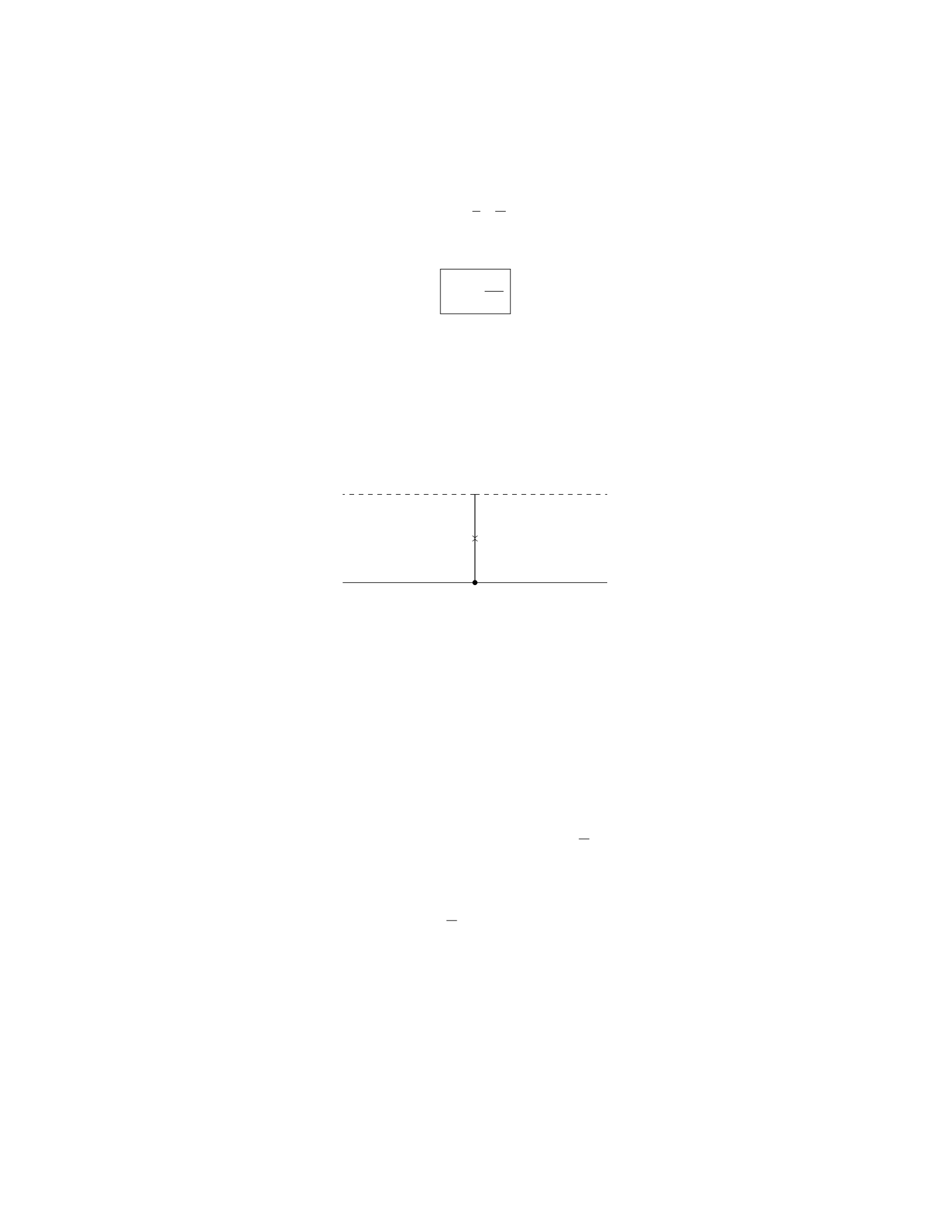
b=1
g·L
2
Therefore, the maximum value of Min terms of L,a,b, and Tis:
M=2T
g
Question 3
Question
A uniform beam of length Land mass Mis supported by a cable attached at
its midpoint as shown in the figure below. The angle between the beam and the
horizontal is θ. Find the tension in the cable.
T
Mg
A B
C
θ
Solution
Step 1: First, we will analyze the forces acting on the beam. The beam has
a weight M g acting downward at its center of mass, and a tension Tacting
upwards at the midpoint where the cable attaches. The normal force exerted
by the hinge at point Aand the horizontal component of the tension cancel
out, while the vertical components of the tension Tsin(θ) and the weight Mg
balance each other out.
Step 2: The torque equation about point Ais given by Pτ= 0. The torque
due to the weight M g about point Ais zero since it acts at the center of mass.
The torque due to the tension Tabout point Ais T·L
2sin(θ), which causes a
clockwise rotation.
Step 3: Setting the net torque equal to zero, we have:
T·L
2sin(θ)=0
Step 4: Solving for the tension T, we find:
T= 0
Step 5: The tension in the cable is zero, which implies that the beam is in
equilibrium and does not rely on the cable to support its weight.
3

Question 4
Question
A spring of stiffness 200 N/m is compressed by 0.05 m. A 2 kg mass is placed on
top of the spring and released. What is the maximum speed of the mass when
it is released? Assume there is no friction between the mass and the surface.
Solution
Step 1: Calculate the potential energy stored in the compressed spring:
Given: Spring stiffness, k= 200 N/m Compression distance, x= 0.05 m
The potential energy stored in the compressed spring is given by the equa-
tion:
P E =1
2kx2
Substitute the given values to find the potential energy:
P E =1
2×200 N/m ×(0.05 m)2
P E =1
2×200 ×0.0025
P E = 0.25 J
Step 2: Calculate the maximum speed of the mass:
At maximum compression, the spring’s potential energy is converted to ki-
netic energy of the mass. Therefore, the maximum speed of the mass can be
calculated using the energy conservation principle:
KE =1
2mv2=P E
Substitute the values and solve for the maximum speed, v:
1
2×2 kg ×v2= 0.25 J
2v2= 0.25
v2=0.25
2
v=r0.25
2
v≈0.28 m/s
Therefore, the maximum speed of the mass when it is released is approxi-
mately 0.28 m/s.
4

Question 5
Question
A block of mass Mrests on a frictionless inclined plane with an incline angle θ.
The block is connected to a spring with a spring constant k. The coefficient of
static friction between the block and the incline is µs. Calculate the maximum
compression of the spring such that the block remains at rest.
Solution
Step 1: Draw a free-body diagram for the block. Let’s draw the forces acting
on the block: - The weight force mg acting vertically downwards. - The nor-
mal force Nacting perpendicular to the incline. - The static friction force fs
acting parallel to the incline and up the incline. - The spring force kx acting
horizontally up the incline.
Step 2: Write out the force equations. In the vertical direction: N=
mg cos(θ). In the horizontal direction: fs+kx =mg sin(θ).
Step 3: Determine the maximum static friction force. The maximum static
friction force is given by fs,max =µsN=µsmg cos(θ).
Step 4: Determine the maximum compression of the spring. At maxi-
mum compression, the static friction force equals its maximum value: kx +
µsmg cos(θ) = mg sin(θ). Solving for x:x=mg(sin(θ)−µscos(θ))
k.
Therefore, the maximum compression of the spring such that the block re-
mains at rest is mg(sin(θ)−µscos(θ))
k.
Question 6
Question
A steel wire of length 2.0 m and cross-sectional area 2.0 mm2is stretched be-
tween two fixed points. The wire stretches by 0.10 mm under a load of 500 N.
Calculate the Young’s modulus of steel.
Solution
Step 1: Identify the given quantities. The given quantities are: Length of the
wire (L) = 2.0 m, Cross-sectional area of the wire (A) = 2.0 mm2= 2.0×10⁻⁶
m2, Change in length of the wire (∆L) = 0.10 mm = 0.10 ×10⁻³m, Load
applied (F) = 500 N.
Step 2: Calculate the initial length of the wire.
L= 2.0 m
Step 3: Calculate the final length of the wire. The final length of the wire
(Lf) can be calculated by adding the change in length to the initial length.
Lf=L+ ∆L
5

Lf= 2.0 m + 0.10 ×10⁻³m
Lf= 2.0001 m
Step 4: Calculate the strain. Strain (ϵ) is defined as the ratio of the change
in length to the original length.
ϵ=∆L
L
ϵ=0.10 ×10⁻³m
2.0 m
ϵ= 5 ×10⁻⁵
Step 5: Calculate the stress. Stress (σ) is defined as the force applied per
unit area.
A= 2.0×10⁻⁶m2
σ=F
A
σ=500 N
2.0×10⁻⁶m2
σ= 2.5×10⁸N/m2
Step 6: Calculate Young’s modulus (Y). Young’s modulus is defined as the
ratio of stress to strain.
Y=σ
ϵ
Y=2.5×10⁸N/m2
5×10⁻⁵
Y= 5 ×10¹² N/m2
Therefore, the Young’s modulus of steel is 5 ×10¹² N/m2.
Question 7
Question
A uniform wooden beam of length Land mass Mis supported by two vertical
ropes attached to its ends. A block of mass mis suspended from the beam a
distance xfrom the left end. Find the tension in each rope when the system is
in equilibrium.
beam_system.png
6

Solution
Let’s consider the forces acting on the beam. There are three forces acting on
the beam: the force of gravity Mg acting at the center of mass of the beam, the
tension T1from the left rope, and the tension T2from the right rope.
Step 1: Set up the equations of equilibrium for the beam Since the
system is in equilibrium, the sum of torques and forces must be zero. The sum
of forces in the y-direction is zero:
T1+T2−Mg = 0
The sum of torques about any point (we choose the left end) is zero:
T2L−Mg(L/2−x)−T1x= 0
Step 2: Solve the equations simultaneously
From equation (1):
T1=Mg −T2(3)
From equation (2):
T2L−Mg(L/2−x)−T1x= 0
Substitute equation (3) into the equation above:
T2L−Mg(L/2−x)−(Mg −T2)x= 0
T2L−Mg(L/2−x)−Mgx +T2x= 0
Solving for T2:
T2L−Mg(L/2−x)−Mgx +T2x= 0
T2L−MgL/2 + Mgx −M gx +T2x= 0
T2L−MgL/2 + T2x= 0
T2(L+x) = MgL/2
T2=MgL
2(L+x)
Step 3: Calculate the tension in T1Substitute T2=Mg −T1into the
expression for T2:
Mg −T1=MgL
2(L+x)
T1=Mg −MgL
2(L+x)
T1=Mg 1−L
2(L+x)
Therefore, the tension in the left rope T1is M g 1−L
2(L+x)and the tension
in the right rope T2is MgL
2(L+x).
7
Question 8
Question
A steel rod of length 2.0 m is attached to a wall at one end and has a weight
of 400 N hanging from the other end. If Young’s modulus for steel is 2.0×10¹¹
N/m2, find the change in length of the rod. (Hint: The weight of the rod is
concentrated at the center of mass, which is 1.0 m away from the wall.)
Solution
Step 1: We first need to calculate the force of gravity acting on the steel rod.
Since the weight of the rod is being concentrated at its center of mass, the force
of gravity can be calculated as F=mg, where mis the mass of the rod and g
is the acceleration due to gravity. Given that the weight of the rod is 400 N, we
have m=400 N
9.81 m/s2≈40.73 kg. Therefore, F= 40.73 kg ×9.81 m/s2≈400 N.
Step 2: Next, we need to calculate the stress applied to the rod. As the
weight is hanging in the center of the rod, the force applied is evenly distributed
along the length. Therefore, the stress can be calculated as σ=F
A, where A
is the cross-sectional area of the rod. The cross-sectional area of the rod can
be calculated as A=πr2, where ris the radius of the rod. Since the rod is
cylindrical, the radius is r=d
2, where dis the diameter of the rod. Given that
the rod is made of steel, Young’s modulus is 2.0×10¹¹ N/m2, and the rod’s
diameter is not provided, we cannot directly calculate the cross-sectional area.
Step 3: We can relate stress (σ) to strain (ϵ) using Hooke’s Law: σ=Eϵ,
where Eis Young’s modulus and ϵis the strain. The strain in the rod can be
calculated as ϵ=∆L
L, where ∆Lis the change in length and Lis the original
length of the rod. Hence, we have ∆L=σL
E.
Step 4: Substituting the values we have calculated, we get ∆L=400 N×1.0 m
2.0×10¹¹ N/m2=
2.0×10⁻³m=2.0 mm. Therefore, the change in length of the rod is 2.0 mm.
Question 9
Question
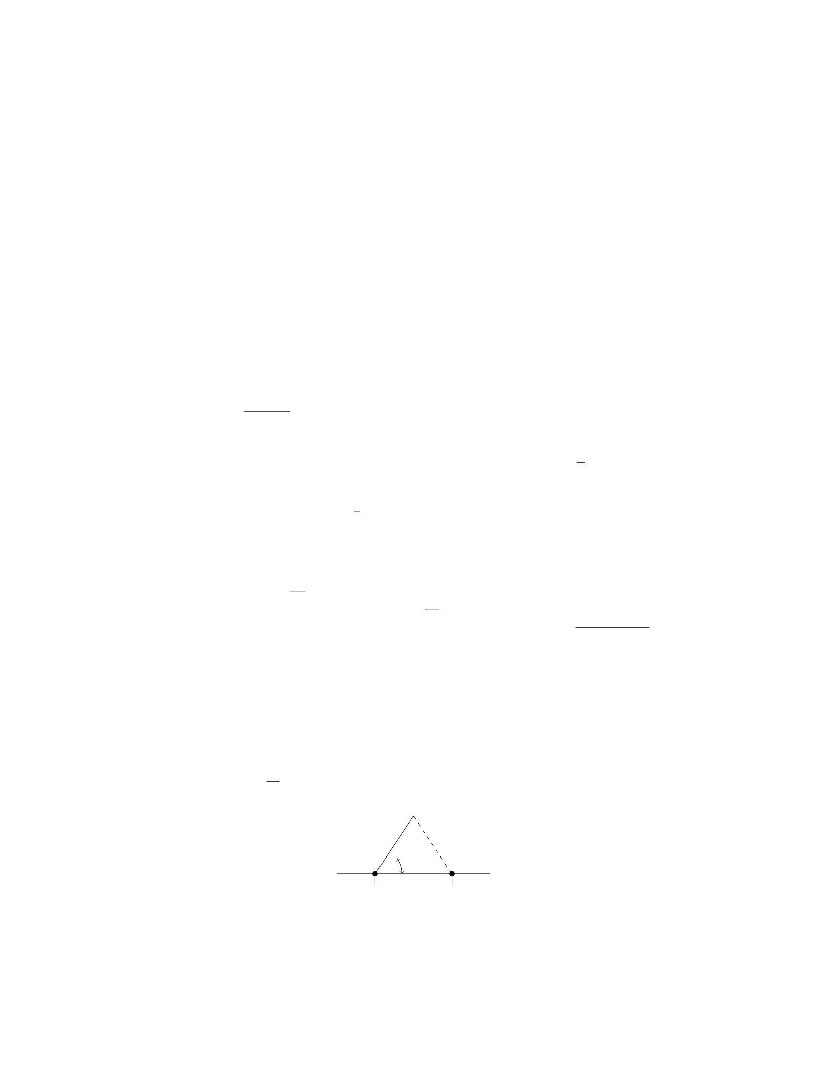
A uniform beam of length Land mass Mis resting horizontally on two sup-
ports, as shown in the diagram below. The beam is also attached to a cable
at a distance 2L
3from one end, which makes an angle θwith the horizontal.
Determine the tension in the cable as a function of θ.
θ
A B
8
Solution
Step 1: Find the forces acting on the beam. Since the beam is in equilibrium,
the sum of the forces and torques acting on the beam must add up to zero.
Let Tbe the tension in the cable, NAand NBbe the normal forces at the
supports Aand Brespectively, W=Mg be the weight of the beam, and Fhoriz
be the horizontal component of the tension.
In the vertical direction:
NA+NB−Mg = 0 ⇒NA=Mg −NB
In the horizontal direction:
Fhoriz = 0
Step 2: Determine the torque about point A. The torque about point Adue
to the weight of the beam and the tension in the cable must balance each other
out.
Torque due to the weight:
τweight =L
2·Mg =MgL
2
Torque due to the tension:
τtension =2L
3·Tsin(θ)
Setting these torques equal to each other:
MgL
2=2L
3Tsin(θ)
Step 3: Solve for the tension in the cable. Solving for T:
T=3Mg
4cot(θ)
Therefore, the tension in the cable as a function of θis T=3Mg
4cot(θ).
Question 10
Question
A cylindrical steel rod of length 2.0 m and diameter 1.0 cm hangs vertically
from the ceiling. The rod supports a weight of 100 N at its lower end. Find the
elongation of the rod. (Take Young’s modulus for steel to be 2.0×10¹¹ N/m2
and ignore the weight of the rod itself.)
9

Solution
Step 1: Calculate the cross-sectional area of the rod.
Given that the diameter of the rod is 1.0 cm, the radius ris 0.5 cm or 0.005 m.
Therefore, the cross-sectional area of the rod Ais:
A=πr2=π(0.005)2m2
Step 2: Calculate the stress in the steel rod.
The stress σis defined as the force Fapplied per unit area A:
σ=F
A=100
π(0.005)2N/m2
Step 3: Calculate the strain in the steel rod.
Using Hooke’s Law, which states that stress σis proportional to strain εby the
equation σ=Y ε, where Yis the Young’s modulus, we can solve for the strain
ε:
ε=σ
Y=100
π(0.005)2×2.0×1011
Step 4: Calculate the elongation of the rod.
The elongation ∆Lcan be found using the equation ∆L=ε×L:
∆L=100
π(0.005)2×2.0×1011 ×2.0
Therefore, the elongation of the rod is calculated to be ∆L.
Question 11
Question
A uniform rod of length Land mass Mis hanging vertically with one end
attached to the ceiling by a hinge. A bullet of mass mand velocity vis fired
directly horizontally into the other end of the rod, where it lodges. Find the
angular speed of the rod just after the bullet lodges.
Solution
Step 1: We will start by determining the initial angular momentum of the
system. The initial angular momentum is given by the sum of the angular
momentum of the bullet and the rod:
Linitial =Lbullet +Lrod
The initial angular momentum of the bullet is:
Lbullet =m×v×L
10
Step 2: The initial angular momentum of the rod is zero since it is at rest
initially. Therefore:
Linitial =m×v×L
Step 3: After the bullet lodges in the rod, their combined mass is (M+m)
and the system rotates about the hinge. The conservation of angular momentum
gives us:
Linitial =Lfinal
m×v×L= (M+m)×ω×L
2
where ωis the angular speed of the rod just after the bullet lodges.
Step 4: Solving for ω, we find:
ω=2m×v
(M+m)
Therefore, the angular speed of the rod just after the bullet lodges is 2m×v
(M+m).
Question 12
Question
A uniform 4 kg horizontal beam is supported by two vertical ropes attached at
each end. A crate with a mass of 10 kg hangs from the middle of the beam. If
each rope makes an angle of 30 degrees with the horizontal, what is the tension
in each rope? Assume the beam is in static equilibrium.
Solution
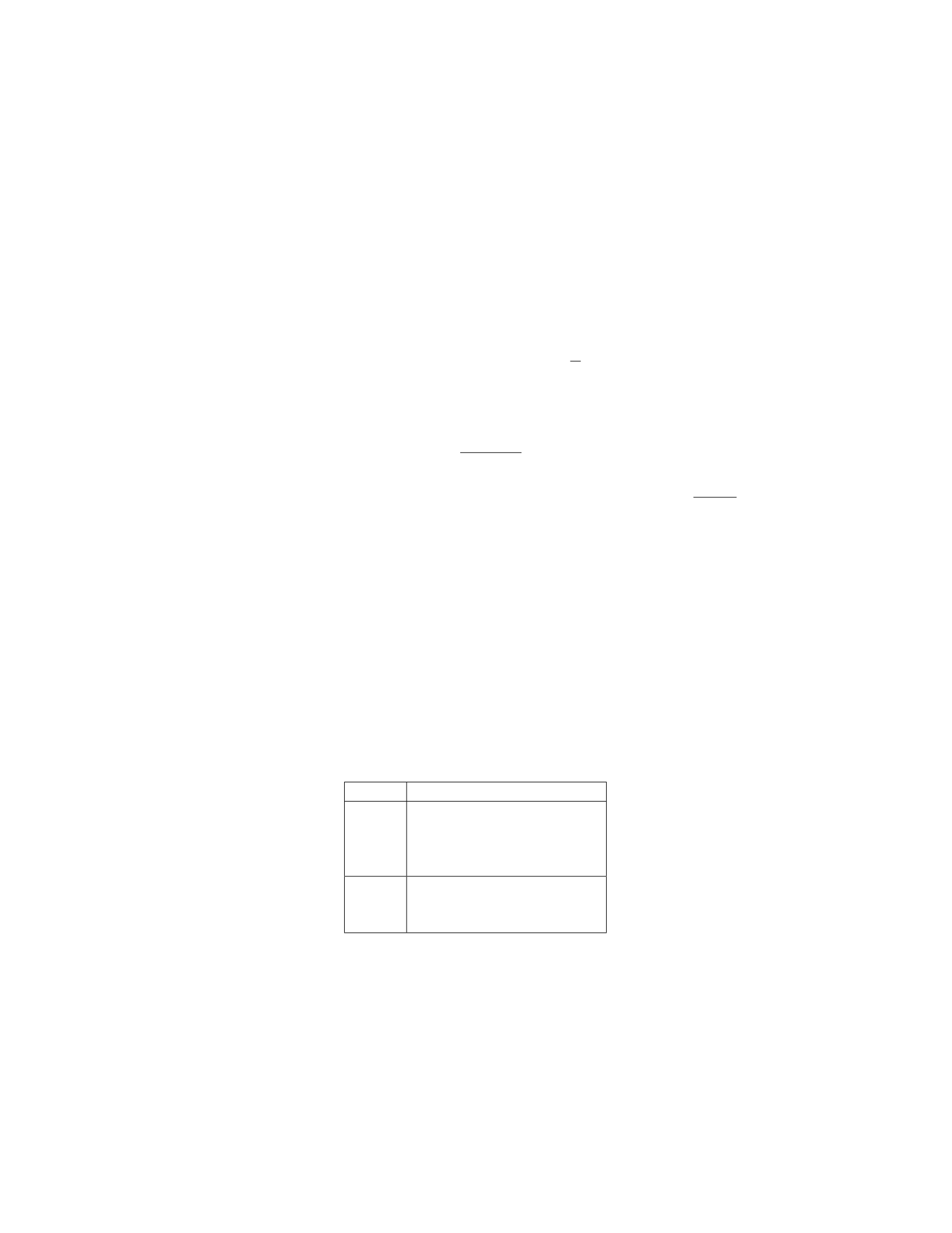
Step 1: Draw a free-body diagram of the system. Label all the forces acting on
the beam and the crate.
Object Forces
Beam
Tension in left rope, T1
Tension in right rope, T2
Weight of beam, Wb
Normal force, N
Crate
Weight of crate, 10g
Tension in left rope, T1
Tension in right rope, T2
Step 2: Write the equations for equilibrium in the x and y directions for the
system. In the x-direction:
T2cos(30◦)−T1cos(30◦)=0
11

In the y-direction:
T1sin(30◦) + T2sin(30◦)−10g−Wb= 0
Step 3: Calculate the weight of the beam and the weight of the crate.
Wb= 4g= 40 N
10g= 10 ×9.8 = 98 N
Step 4: Substitute the known values and solve the equations simultaneously.
From the x-equation:
T2=T1
Substitute Wb, 10g, and T2=T1into the y-equation:
T1sin(30◦) + T1sin(30◦)−10 ×9.8−40 = 0
2T1sin(30◦) = 138
T1=138
2 sin(30◦)= 138
Therefore, the tension in each rope is 138 N.
Question 13
Question
A cylinder of mass mand radius ris floating in a liquid of density ρ. The top
surface of the cylinder is at a depth hbelow the liquid surface. Determine the
magnitude of the normal force exerted by the liquid on the bottom surface of
the cylinder.
Solution
Step 1: First, let’s determine the volume of the part of the cylinder submerged
in the liquid. The volume Vcan be found using the formula for the volume of
a cylinder: V=πr2h.
Step 2: The weight of the liquid displaced by the submerged part of the
cylinder is equal to the weight of the cylinder and is given by the formula
m=ρV g, where gis the acceleration due to gravity.
Step 3: The normal force exerted by the liquid on the bottom surface of
the cylinder is equal in magnitude to the weight of the liquid displaced by the
cylinder. Therefore, the normal force Fliquid =ρV g.
Step 4: Substituting the expression for Vinto the formula for the normal
force, we get Fliquid =ρπr2hg. Thus, the magnitude of the normal force exerted
by the liquid on the bottom surface of the cylinder is ρπr2hg .
12

Question 14
Question
A uniform horizontal beam of mass Mand length Lis supported by two vertical
cables attached at the ends of the beam. The tension in the left cable is given by
T1and the tension in the right cable is given by T2. If the beam is in equilibrium,
determine the tensions T1and T2in terms of M,L, and acceleration due to
gravity g.
Solution
1. Draw a free-body diagram for the beam. The forces acting on the beam
include its weight W=M g acting downwards at the beam’s center of mass, the
tension T1in the left cable acting upwards at the left end, and the tension T2
in the right cable acting upwards at the right end.
2. Since the beam is in equilibrium, the net force and net torque on the
beam are both zero.
3. Write the force balance equation in the vertical direction:
T1+T2=Mg
4. To write the torque balance equation, choose a pivot point where only
one of the cable forces will generate torque. Let’s choose the pivot at the
left end of the beam. The torque due to the tension T2about this point is
clockwise and equals T2·L. The torque due to the weight Mg about this point
is counterclockwise and equals −1
2L·Mg. The torque equation is:
T2·L−1
2L·Mg = 0
5. Solve the force balance equation for T2:
T2=Mg −T1
6. Substitute T2=Mg −T1into the torque equation:
(Mg −T1)·L−1
2L·Mg = 0
MgL −T1L−1
2MgL = 0
7. Simplify the equation:
1
2T1L=1
2MgL
T1=Mg
13

8. Finally, substitute T1=Mg back into the force balance equation:
T2=Mg −Mg = 0
Therefore, the tensions are:
T1=Mg
T2= 0
Question 15
Question
A uniform beam of length Land mass Mis supported by a pivot at one end,
with a weight Whanging from the other end. If the beam makes an angle θ
with the horizontal, determine the tension in the pivot and the force exerted by
the pivot on the beam. Assume that the beam is in equilibrium and neglect the
mass of the beam.
Solution
Step 1: First, draw a free body diagram of the beam and the forces acting on it.
Let Tbe the tension in the pivot, Nbe the normal force exerted by the pivot,
and Wbe the weight hanging from the beam. The forces can be broken down
into their x and y components:
In the xdirection: N=Tsin θ
In the ydirection: W=Mg +Tcos θ
Step 2: Since the system is in equilibrium, the sum of the torques about any
point must be zero. Let’s take torques about the pivot point. The torque due to
the weight Wis negative (since it tends to rotate the beam counterclockwise),
while the torque due to the normal force Nand the tension Tare positive
(since they tend to rotate the beam clockwise). The torque due to Wis given
by −W·L
2sin θ, and the torque due to Nis N·L. The torque equation becomes:
N·L−W·L
2sin θ= 0
Step 3: Substituting the expressions for Nand Winto the torque equation:
Tsin θ·L−(Mg +Tcos θ)·L
2sin θ= 0
14
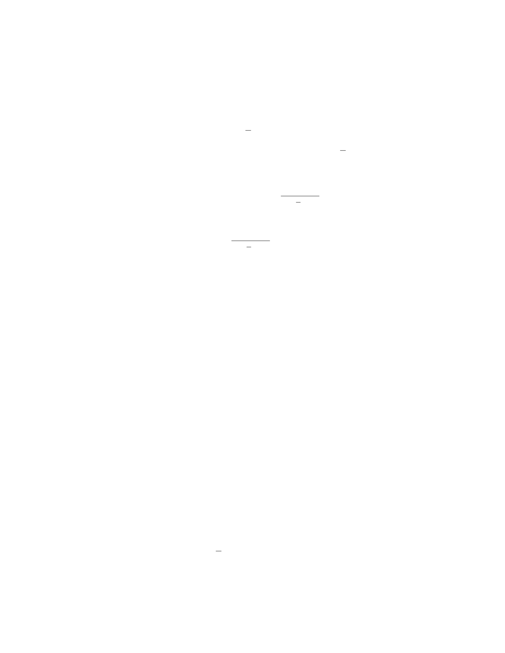
Step 4: Solving for T, we get:
Tsin θ·L−(Mg +Tcos θ)·L
2sin θ= 0
Tsin θ·L= (Mg +Tcos θ)·L
2sin θ
2Tsin θ·L= (Mg +Tcos θ)·Lsin θ
2T=Mg +Tcos θ
T=Mg
2−L
Lcos θ
Step 5: To find N, substitute the expression for Tback into N=Tsin θ:
N=Mg
2−L
Lcos θ·sin θ
Question 16
Question
A uniform rod of length Land mass Mis supported by a pivot at one end. A
force Fis applied perpendicular to the rod at a distance xfrom the pivot. Find
the condition for the rod to be in equilibrium.
Solution
To find the condition for the rod to be in equilibrium, we need to balance the
torques acting on the rod.
Step 1: Calculate the torque due to the gravitational force on the rod. The
gravitational force acts at the center of mass, which is at a distance L/2 from
the pivot point.
The torque due to the gravitational force (τg) is given by:
τg= (L/2) ·M·g
Step 2: Calculate the torque due to the force F. The torque due to the
force Fis given by:
τF=x·F
Step 3: Set up the condition for equilibrium. For the rod to be in equilib-
rium, the net torque acting on the rod must be zero. Therefore, we have:
τnet =τg−τF= 0
Substituting in the expressions for τgand τFand setting the net torque to
zero gives: L
2·M·g−x·F= 0
15

Step 4: Solve for the condition. Solving the above equation for F, we get:
F=M·g·L
2x
Therefore, the condition for the rod to be in equilibrium is when the force
Fis equal to M·g·L
2x.
Question 17
Question
A 2 kg mass is suspended from a vertical spring, causing it to stretch 10 cm.
The spring constant is 400 N/m. Another identical mass is then added to the
first mass, causing the spring to stretch an additional 5 cm. What is the period
of oscillation for the combined system of two masses?
Solution
Step 1: Determine the total mass of the system of two masses. The mass of
each mass is 2 kg, so the total mass of the system is 2 kg + 2 kg = 4 kg.
Step 2: Calculate the total stretch in the spring. The initial stretch was 10
cm. When the second mass is added, the spring stretches an additional 5 cm,
making the total stretch 15 cm.
Step 3: Calculate the effective spring constant of the two-mass system. The
spring constant for each mass is 400 N/m. The effective spring constant for the
two-mass system is calculated as:
keff =k1·k2
k1+k2
keff =400 N/m ×400 N/m
400 N/m + 400 N/m
keff =160000 N2/m2
800 N/m = 200 N/m
Step 4: Calculate the period of oscillation for the two-mass system. The
period of oscillation for a mass-spring system is given by:
T= 2πrm
k
Where mis the total mass and kis the effective spring constant.
T= 2πs4 kg
200 N/m
T= 2πp0.02 s2/m=0.282 s
Therefore, the period of oscillation for the combined system of two masses
is 0.282 seconds.
16

Question 18
Question
A uniform horizontal shelf of length Land weight Wis supported by two vertical
springs at its ends, each with spring constant k. A block of weight wis placed
on the shelf, a distance xfrom the left end. If the springs are to support the
shelf and block without compression or extension, determine the force constant
kof the springs in terms of the given parameters.
Solution
1. Draw a free-body diagram of the system. Label the forces acting on the shelf
and block, including the normal forces from the springs and the weight of the
shelf and block.
2. Write out the equilibrium equations in the vertical and horizontal direc-
tions. For equilibrium in the vertical direction, the sum of the vertical forces
must equal zero. For equilibrium in the horizontal direction, the sum of the
horizontal forces must equal zero.
3. In the vertical direction, the forces acting on the shelf and block are the
weight of the block w, the weight of the shelf W, and the normal forces from
the two springs. Set up the equation for equilibrium in the vertical direction.
4. In the horizontal direction, the only force acting on the block is the
normal force from the spring on the left, and the only force acting on the shelf
is the normal force from the spring on the right. Write out the equation for
equilibrium in the horizontal direction.
5. Knowing that the sum of the forces is zero, solve the system of equations
to find the normal forces from the springs in terms of the given parameters.
6. Express the normal forces in terms of k,x,L,w, and W. Use these
expressions to find the force constant kin terms of the given parameters.
Therefore, the force constant kof the springs should be 4wx
L(2L−x).
Question 19
Question
A metal rod of length Lis suspended vertically from one end. A weight W
is attached to the other end of the rod, causing it to stretch by an amount
∆L. The rod has a uniform cross-sectional area Aand a Young’s modulus Y.
Calculate the stress and strain in the rod.
Solution
Step 1: To calculate the stress (σ) in the rod, we can use the formula for stress:
σ=F
A
17

where Fis the force causing the stress and Ais the cross-sectional area of the
rod. In this case, the force causing the stress is the weight W, so F=W.
Therefore, we have:
σ=W
A
Step 2: Next, let’s calculate the strain (ϵ) in the rod using Hooke’s Law.
Hooke’s Law states that the strain in a material is directly proportional to the
stress applied to it. Therefore, we have:
ϵ=∆L
L
Step 3: Substituting the given values into the formulas, we have:
σ=W
A
ϵ=∆L
L
Step 4: We can also express stress in terms of Young’s modulus and strain:
σ=Y·ϵ
Substitute in the expressions for stress and strain:
W
A=Y·∆L
L
Step 5: Now, we can solve for stress and strain:
σ=W
A
ϵ=∆L
L
Therefore, the stress in the rod is W
Aand the strain in the rod is ∆L
L.
Question 20
Question
A uniform beam of mass mand length Lis supported by a pivot at one end
and a rope attached 3/4 of its length from the other end. A weight Wis hung
from the end of the beam. If the beam is in equilibrium, determine the tension
in the rope.
18

Solution
1. Draw a free-body diagram of the beam. Label the pivot point as A, the
attachment point of the rope as B, the location of the weight Was C, and the
center of mass of the beam as G.
2. Apply the rotational equilibrium condition:
Xτ= 0
The torque at point Adue to the weight and tension is equal to 0 since the
beam is in rotational equilibrium:
τA= 0
3. Find the torque at point Bdue to the weight and tension:
τB=WL
4−T3L
4
4. The torque at point Bis also equal to 0 since the beam is in rotational
equilibrium:
τB= 0
5. Set the torque equation equal to 0 and solve for the tension T:
WL
4−T3L
4= 0
T=1
3W
Therefore, the tension in the rope is 1
3W.
Question 21
Question
A uniform beam of length Land mass Mrests horizontally on two supports, one
at each end. A block of mass mis placed a distance xfrom the left end of the
beam. If the beam just begins to tip when the block is placed on it, determine
the coefficient of static friction between the beam and the left support. Assume
the block does not slide on the beam.
Solution
Step 1: Draw a free-body diagram of the beam and block system. The forces
acting on the system are the gravitational forces mg and Mg acting on the block
and beam respectively, the normal forces N1and N2acting at the supports, and
19

the frictional force facting between the beam and the left support due to the
impending tipping motion.
Step 2: Write out the equilibrium conditions for the beam and block system
in the vertical and rotational directions. In the vertical direction: - N1+N2=
mg +Mg In the rotational direction about the point where the left support is:
-MgL/2−f·x=m·g·x
Step 3: Express the frictional force in terms of the coefficient of static friction.
The maximum static friction force that could act at the left support without
tipping the beam is fmax =µN1=µ(mg +Mg).
Step 4: Substitute fmax into the equilibrium condition for rotation to get an
expression in terms of µ: - µ(mg +Mg)·x=M·g·L/2
Step 5: Solve for the coefficient of static friction µ: - µ=M gL
2x(mg+M g)
Question 22
Question
A uniform wooden beam of length Land mass Mis supported by a rope attached
at a distance xfrom one end. If the beam makes an angle θwith the horizontal,
find the tension in the rope.
Solution
Step 1: We begin by drawing a free body diagram of the beam. Let Tbe
the tension in the rope, Rbe the force exerted by the pivot point, mg be the
gravitational force acting at the center of the beam, and Nbe the normal force
exerted by the pivot point on the beam.
Step 2: Resolve the gravitational force into components parallel and per-
pendicular to the beam. The component parallel to the beam will balance the
tension in the rope while the component perpendicular to the beam will balance
the normal force.
Step 3: Summing the forces vertically and horizontally, we get: Vertically:
Tcos θ=mg Horizontally: Tsin θ=R
Step 4: The torque about the pivot point is zero since the beam is in equilib-
rium. The torque due to the tension and the weight of the beam must balance
each other. Taking torque about the pivot point: Tsin θ·x=1
2L·M·g·cos θ
Step 5: From Step 3, we can express Rin terms of T:Tsin θ=RSubstitute
this into the torque equation: Tsin θ·x=1
2L·M·g·cos θ
Step 6: Solve the torque equation for Tto find the tension in the rope:
T=1
2L·M·g·cos θ/(xsin θ)T=1
2M·g·L·cos θ/x
Therefore, the tension in the rope is 1
2M·g·L·cos θ/x.
20

Question 23
Question
A uniform wooden beam of length Land mass Mis supported by a pivot at
one end. A ball of mass mis attached to the beam at a distance L
3from the
pivot, as shown in the diagram below. If the beam is in equilibrium and the
pivot exerts no force on the beam other than a vertical force to hold it up, find
the tension in the wire holding the ball in place.
[Diagram not shown]
Solution
1. Draw a free-body diagram of the beam. The forces acting on the beam are
its weight M g, the tension in the wire T, and the normal force Nfrom the
pivot. 2. Choose a coordinate system where the positive y-axis points upwards.
3. Write out the force equilibrium equations:
XFx= 0 and XFy= 0
4. Resolve forces parallel and perpendicular to the beam.
Parallel to beam: Tsin θ=Mg L
2(Equation 1)
Perpendicular to beam: N−Tcos θ=Mg L
3(Equation 2)
5. To find T, first eliminate θby dividing Equation 2 by Equation 1:
N−Tcos θ
Tsin θ=Mg L
3
Mg L
2
N
Tsin θ−Tcos θ
Tsin θ=1
32
1
N
Tsin θ−cot θ=2
3
6. Recognize that cot θ=1
tan θ=1
Tcos θ
Mg(L
2)
=Mg(L
2)
Tcos θ. Substitute this into the
expression from step 5:
N
Tsin θ−Mg L
2
Tcos θ=2
3
7. Rearrange the equation to solve for T:
N
T−Mg L
2
T=2
3sin θ
21

N
T=Mg L
2
T+2
3sin θ
T=N
Mg(L
2)
T+2
3sin θ
8. Since the beam is in equilibrium, the sum of vertical forces must be zero:
N=Mg L
3. Substitute this into the equation for T:
T=Mg L
3
Mg(L
2)
T+2
3sin θ
9. The tension in the wire holding the ball in place, T, can be found by solving
the above equation.
Question 24
Question
A uniform beam of length Land mass Mis supported at a pivot point located
at a distance afrom one end. A force Fis applied at the opposite end of the
beam. If the beam is in equilibrium, determine the tension in the beam at a
distance bfrom the pivot point.
Solution
To solve this problem, we will use the condition for rotational equilibrium: the
sum of the torques acting on the beam must be zero.
Step 1: Identify the torques The torque due to the force Fabout the
pivot point can be calculated as τ=F(L−b). The torque due to the gravita-
tional force acting on the beam itself can be calculated as τ′=Mg L
2−b.
Step 2: Set up the equilibrium condition In rotational equilibrium,
the sum of the torques must be zero. Thus, we have:
τ+τ′= 0
F(L−b) + Mg L
2−b= 0
Step 3: Solve for the tension Solving the equation above for F, we get:
F=−MgL
2+Mgb
Therefore, the tension in the beam at a distance bfrom the pivot point is
−MgL
2+Mgb.
22

Question 25
Question
A uniform beam of length Land mass Mis supported at two points: one-third
of the way from the left end, with a support force F1, and two-thirds of the
way from the left end, with a support force F2. If the beam is horizontal and in
equilibrium, determine the magnitudes of F1and F2in terms of M,L, and g.
Solution
Step 1: Draw a free-body diagram of the beam with the support forces F1and
F2. Step 2: Write down the force balance equations in the xand ydirections.
The beam is in equilibrium, so the net force and net torque must be zero. In
the xdirection, the equation is:
F1+F2= 0
In the ydirection, the equation is:
Mg −F1−F2= 0
Step 3: Solve the system of equations. From the xdirection equation, we get
F2=−F1. Substituting this into the ydirection equation gives:
Mg −F1−(−F1) = 0
Mg −2F1= 0
F1=Mg
2
So, F1=Mg
2. Step 4: Calculate F2using the relation F2=−F1. Substituting
F1=Mg
2into this relation gives:
F2=−Mg
2
Therefore, F2=−Mg
2(Note the negative sign indicates the direction of the
force). Thus, the magnitudes of F1and F2in terms of M,L, and gare F1=M g
2
and F2=−Mg
2.
Question 26
Question
A uniform rod of length Land mass Mis pivoted at one end and is in equilibrium
at an angle θwith the horizontal. The free end of the rod is attached to a wall
by a string, making an angle ϕwith the horizontal. If the tension in the string
is T, determine the distance xto the point where the rod is in contact with the
wall.
23

Solution
Step 1: Draw a free body diagram of the rod. Mark all forces acting on the rod.
Step 2: Resolve the forces into their horizontal and vertical components.
The forces acting on the rod are the weight M g, the tension T, and the normal
force Nfrom the wall.
Step 3: Write the equilibrium conditions in the horizontal and vertical di-
rections. Equilibrium in the horizontal direction gives Ncos ϕ=Tsin θ.
Step 4: Equilibrium in the vertical direction gives Nsin ϕ=M g −Tcos θ.
Step 5: Solve for the normal force Nin terms of Tand the angles: N=
Tsin θ
cos ϕ.
Step 6: Substitute the expression for Ninto the vertical equilibrium equation
and solve for the tension T:T=Mg
sin ϕ+cos θ.
Step 7: To find the distance x, use the fact that the torque about the pivot
point must be zero. Integrate the torque contributions of the weight and tension
force along the rod to find x.
Step 8: Integrating the torque from the weight of the rod: Rx
0
(M/L)gx
2dx =
Mg
2Lx2.
Step 9: Integrating the torque from the tension T:RL
xT x cos θdx =Tcos θL2
2−x2
2.
Step 10: Set the total torque equal to zero and solve for x:Mg
2Lx2=
Tcos θL2
2−x2
2.
Step 11: Substitute the expression for Tfrom step 6 into the torque equation
and solve for x. The final expression for xwill be in terms of L,M,g,θ, and ϕ.
Question 27
Question
A rectangular block of wood of mass 2.5 kg and dimensions 20 cm×16 cm×8 cm
floats in water with the 20 cm side horizontal. Find the distance ”d” below
the water surface where the block is in equilibrium. The density of water is
1000 kg/m3and the acceleration due to gravity is 9.81 m/s2.
Solution
Step 1: Calculate the volume of the block. The volume of the block can be
calculated using the formula:
V=l×w×h
where l= 20 cm, w= 16 cm, and h= 8 cm.
Converting all measurements to meters:
V= 0.20 m ×0.16 m ×0.08 m = 0.00256 m3
24

Step 2: Calculate the weight of the block. The weight of the block is given
by:
W=m×g
where m= 2.5 kg and g= 9.81 m/s2.
W= 2.5 kg ×9.81 m/s2= 24.525 N
Step 3: Calculate the buoyant force acting on the block. The buoyant force
is given by:
Fb=ρ×g×V
where ρ= 1000 kg/m3(density of water) and V= 0.00256 m3.
Fb= 1000 kg/m3×9.81 m/s2×0.00256 m3= 25.1136 N
Step 4: Calculate the distance ”d” below the water surface. At equilibrium,
the weight of the block is equal to the buoyant force acting on it:
W=Fb
24.525 N = 25.1136 N
Let hbe the depth submerged
Vsubmerged =l×w×h
0.20 m ×0.16 m ×h= 0.00256 m3
h=0.00256 m3
0.20 m ×0.16 m =0.00256 m3
0.032 m2= 0.08 m
Therefore, the block is in equilibrium at a distance of 8 cm below the water
surface.
Question 28
Question
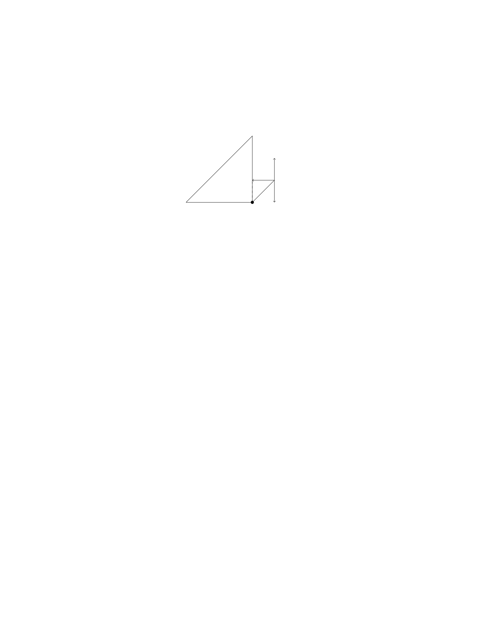
A uniform rod of length Land mass Mis supported by a pivot at one end, as
shown in the figure below. A block of mass mis attached to the free end of
the rod. The system is in equilibrium, with the rod making an angle θwith the
vertical. Find an expression for the tension Tin the rod and the normal force
Nexerted by the pivot on the rod in terms of m,M,L,g, and θ.
rod_pivot.png
25
Solution
Step 1: Begin by drawing a free body diagram of the block and the forces acting
on it.
Pivot
N
Tmg
ℓ θ
Step 2: Write out the equations of equilibrium. In the vertical direction:
N+Tsin(θ)−mg = 0
In the horizontal direction:
Tcos(θ) = 0
Step 3: Solve the horizontal equation Tcos(θ) = 0 to find T= 0. This
means there is no horizontal acceleration, which is expected since the block is
not moving horizontally.
Step 4: Substitute T= 0 into the vertical equilibrium equation:
N+ 0 −mg = 0
Thus, N=mg.
Therefore, the tension in the rod is T= 0 and the normal force exerted by
the pivot on the rod is N=mg.
Question 29
Question
A solid cylindrical rod of length Land radius Ris hanging vertically from a
ceiling. A weight Wis attached to the free end of the rod. The rod has a
uniform density ρand Young’s modulus Y. Determine the elongation of the rod
due to the weight attached to it.
Solution
Step 1: First, we will determine the mass of the rod. The mass of the rod can
be calculated as:
m=ρ·V
26

where Vis the volume of the rod. The volume of a solid cylinder with radius
Rand length Lis given by:
V=πR2L
Step 2: Substituting Vinto the equation for mass, we have:
m=ρ·πR2L
Step 3: Next, we will calculate the force due to gravity acting on the rod.
The force acting on the rod is equal to the weight of the rod plus the weight
attached to it:
F=mg =ρ·πR2L·g
Step 4: The stress due to the weight is given by:
σ=F
A
where Ais the cross-sectional area of the rod. The cross-sectional area of a
cylinder is A=πR2.
Step 5: Substituting the values of Fand Ainto the equation for stress, we
get:
σ=ρ·πR2L·g
πR2
Step 6: Using Hooke’s Law, the stress is related to the strain by:
σ=Y·ϵ
where ϵis the strain.
Step 7: Solving for ϵ, we find:
ϵ=ρ·πR2L·g
Y πR2
Step 8: The elongation ∆Lof the rod is related to the original length Land
the strain ϵby:
∆L=L·ϵ
Step 9: Substituting the value of ϵinto the equation for elongation, we have:
∆L=L·ρ·πR2L·g
Y πR2
Question 30
Question
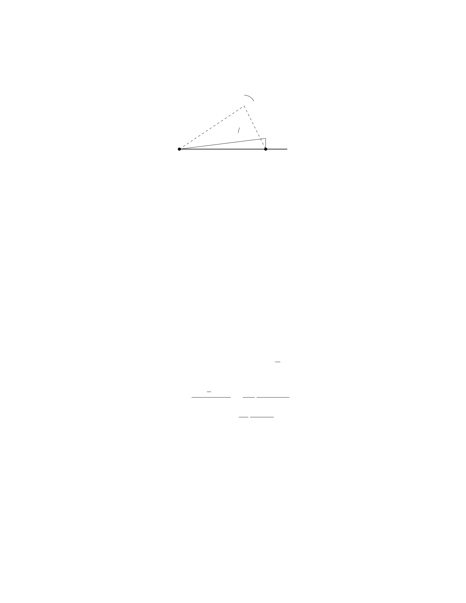
A uniform beam of length Land mass Mis attached to a wall by a hinge at
one end. The beam makes an angle θwith the horizontal and is supported by
a cable making an angle ϕwith the beam, as shown in the figure below.
27
θ
ϕ
O A
Determine the tension in the cable.
Solution
Step 1: Summing the forces in the xdirection and ydirection, we have:
XFx=Tsin ϕ−0 = 0 (since the beam is in equilibrium)
XFy=Tcos ϕ−Mg = 0
Step 2: Solving the equation PFx= 0 for T, we get:
Tsin ϕ= 0 =⇒T= 0
Step 3: Substituting T= 0 into PFy= 0, we find:
0 cos ϕ−Mg = 0 =⇒Mg = 0
Step 4: This implies that M= 0, which is not a realistic scenario. Therefore,
the tension in the cable must be non-zero.
Step 5: We realize that Tcannot be solved using the forces in the xand
ydirections since the beam is not in equilibrium. To solve for T, we need to
incorporate the torque about point O.
Step 6: The torque equation about point O is given by:
Xτ= 0 = T L sin(ϕ−θ)−Mg L
2cos θ
Step 7: Solving for T, we find:
T=Mg L
2cos θ
Lsin(ϕ−θ)=Mg
2
cos θ
sin(ϕ−θ)
Therefore, the tension in the cable is Mg
2
cos θ
sin(ϕ−θ).
Question 31
Question
A uniform rod of length Land mass Mis held horizontally with one end against
a vertical wall. A massless string is attached to the other end of the rod and
is pulled horizontally by a force Fin the direction perpendicular to the rod. If
the coefficient of static friction between the wall and the rod is µs, determine
the maximum force Fmax that can be applied before the rod starts to slip.
28

Solution
Step 1: Draw the Free Body Diagram (FBD) for the rod.
Step 2: Analyze the forces acting on the rod. - The forces acting on the
rod are the tension in the string (T), the gravitational force (Mg) acting on
the center of mass, the normal force (N) exerted by the wall on the end of the
rod, the frictional force (fs) exerted by the wall on the end of the rod, and the
applied force F.
Step 3: Write the equations for equilibrium in the vertical and horizontal
directions. In the vertical direction: N−M g = 0
In the horizontal direction: T+fs+F= 0
Step 4: Determine the expressions for the tension T, the frictional force fs,
and the normal force N.
Step 5: Express the frictional force fsin terms of the coefficient of static
friction µsand the normal force N:fs=µsN
Step 6: Substitute the expressions for Tand fsalong with N=Mg into
the equation for equilibrium in the horizontal direction, and solve for Fmax.
−T−µsMg +F= 0
Step 7: Solve for the maximum force Fmax:Fmax =T+µsMg
Step 8: Express the tension Tin terms of Fmax and solve for Fmax:Fmax =
2µsMg
Question 32
Question
A uniform rod of length Land mass Mis suspended horizontally by two vertical
wires attached at each end of the rod. If each wire makes an angle θwith the
vertical, find the tension in each wire.
Solution
Let’s denote the tension in each wire as T. We’ll start by drawing a free-body
diagram of the rod.
Step 1: Draw a free-body diagram of the rod.
The forces acting on the rod are its weight Wacting downwards (with mag-
nitude Mg), and the tensions Tacting in the upward direction at each end of
the rod. The angles between the tension forces and the horizontal are both θ.
Step 2: Resolve forces along the vertical and horizontal directions.
Resolving forces along the vertical direction:
2Tcos(θ) = Mg or T=Mg
2 cos(θ)
Step 3: Simplify the expression for tension in each wire.
Thus, the tension in each wire is T=M g
2 cos(θ).
29

Question 33
Question
A uniform rod of length Land mass Mis lying on a frictionless horizontal
surface. The rod is pivoted about a point Plocated at one end of the rod. A
point-like object with mass mis placed a distance xfrom the pivot point on the
rod. The system is in equilibrium.
If the rod is moved such that the hanging object is now a distance yfrom the
pivot point, determine the new angle θthat the rod makes with the horizontal.
Solution
1. We will begin by analyzing the forces acting on the system when the object
is placed at a distance xfrom the pivot point:
The forces acting on the mass mare: - The force of gravity, with magnitude
m·g, acting downward. - The normal force from the rod, with a vertical
component equal to Ncos θpointing upward and a horizontal component equal
to Nsin θpointing to the left. - The tension force Tin the rod, with a horizontal
component equal to Tcos θpointing to the right and a vertical component equal
to Tsin θpointing upward.
2. Since the system is in equilibrium, the sum of the forces in the xand y
directions must be zero:
Sum of forces in the xdirection:
Tcos θ=m·g
Sum of forces in the ydirection:
Ncos θ=m·g
3. Next, we will analyze the forces acting on the system when the object is
placed at a distance yfrom the pivot point:
The forces acting on the mass mare: - The force of gravity, with magnitude
m·g, acting downward. - The normal force from the rod, with a vertical
component equal to Ncos θpointing upward and a horizontal component equal
to Nsin θpointing to the left. - The tension force Tin the rod, with a horizontal
component equal to Tcos θpointing to the right and a vertical component equal
to Tsin θpointing upward.
4. Again, since the system is in equilibrium, the sum of the forces in the x
and ydirections must be zero:
Sum of forces in the xdirection:
Tcos θ=m·g
Sum of forces in the ydirection:
Ncos θ=m·g
30

5. Now, let’s find the relationship between xand y:
For the initial position:
x=Lcos θ
For the final position:
y=Lcos θ
6. Equating xand y, we have:
Lcos θ=Lcos θ
7. Therefore, the angle θremains the same when the object is moved from
a distance xto a distance yfrom the pivot point.
Question 34
Question
A 2-meter long uniform beam with a weight of 400 N is supported by a cable
attached 1.2 meters from one end of the beam. A 600 N person stands 0.8
meters from the same end. What is the tension in the cable?
Solution
Step 1: Calculate the torques about the point where the cable is attached. Let’s
choose the clockwise direction as positive. The torque due to the person at one
end of the beam is given by:
Torqueperson =−600 N ×0.8 m = −480 Nm
The torque due to the weight of the beam is given by:
Torquebeam weight =−400 N ×2 m = −800 Nm
The torque due to the tension in the cable can be calculated as follows: Let’s
denote the tension in the cable as T. The distance of the cable attachment
point from the pivot is 1.2 meters. This contributes to the overall torque in the
counter-clockwise direction:
Torquetension =T×1.2 m
Since the beam is in equilibrium, the sum of torques must equal zero:
XTorques = Torqueperson + Torquebeam weight + Torquetension = 0
−480 Nm −800 Nm + T×1.2 m = 0
Step 2: Solve for the tension in the cable.
T×1.2 m = 1280 Nm
31

T=1280 Nm
1.2 m
T= 1066.67 N
Therefore, the tension in the cable supporting the beam is 1066.67 N.
Question 35
Question
A uniform beam of length 4.0 m and mass 60 kg is supported by a rope attached
to its end. A 120 kg mass is placed 1.0 m from the end of the beam, causing the
beam to be in rotational equilibrium. Determine the tension in the rope and
the force exerted by the pivot on the beam.
Solution
Step 1: Set up the free-body diagram for the beam. The forces acting on the
beam are: - The weight of the beam acting at its center of mass ( L
2from the
pivot) - The tension in the rope acting vertically upwards at the end of the
beam - The weight of the 120 kg mass acting 1m from the end of the beam -
The force exerted by the pivot at the left end of the beam
Step 2: Write down the equilibrium condition for the beam. The sum of
the torques acting on the beam must be zero. Taking the pivot as the point of
rotation, we have:
Xτ= 0
T·4.0−60 ·9.8·4.0
2−120 ·9.8·1=0
Step 3: Solve for the tension in the rope.
4T−60 ·9.8·2 = 120 ·9.8
T=120 ·9.8 + 60 ·9.8·2
4
T=1176
2
T= 588 N
Step 4: Solve for the force exerted by the pivot on the beam. The sum of
the forces in the vertical direction must be zero.
Fpivot −60 ·9.8−120 ·9.8=0
Fpivot = 60 ·9.8 + 120 ·9.8
Fpivot = 1764 N
Therefore, the tension in the rope is 588 N and the force exerted by the pivot
on the beam is 1764 N.
32

Solving the equation for m:
m=M
4
Therefore, the maximum mass mthat can be hung at one end without
tipping the beam is M
4.
Question 2
Question
A uniform beam of length Land mass Mis supported by two strings at distances
aand bfrom one end. If the beam is in equilibrium and each string can support
a maximum tension of T, determine the maximum value of Min terms of L,a,
b, and T.
Solution
Step 1: Draw a free-body diagram of the beam. Let’s denote the tensions in
the strings as T1and T2. The gravitational force acting on the beam can be
represented as Mg acting at the center of mass of the beam.
Step 2: Write down the equilibrium equations. In the vertical direction, we
have the following equilibrium equation:
T1+T2=Mg
In the torque equilibrium about the left support (string 1), we have:
T2·b=Mg ·L
2
Step 3: Substitute T1=Tand T2=Tinto the equations. Substitute T1=T
and T2=Tinto the equilibrium equations:
T+T=Mg
T·b=Mg ·L
2
Step 4: Solve for Min terms of L,a,b, and T. From the first equation, we
get:
2T=Mg
M=2T
g
Substitute M=2T
ginto the second equation:
T·b=2T
g·L
2
2
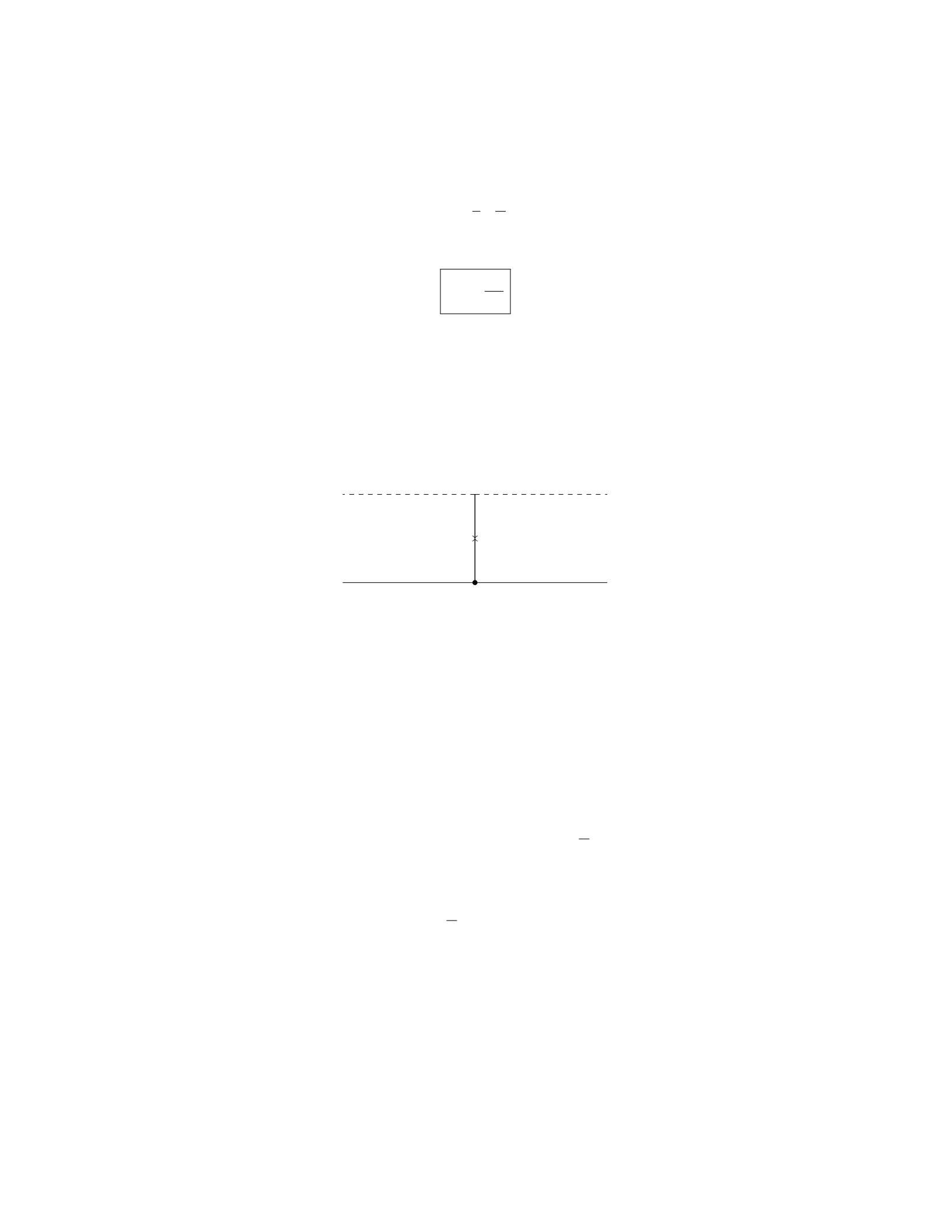
b=1
g·L
2
Therefore, the maximum value of Min terms of L,a,b, and Tis:
M=2T
g
Question 3
Question
A uniform beam of length Land mass Mis supported by a cable attached at
its midpoint as shown in the figure below. The angle between the beam and the
horizontal is θ. Find the tension in the cable.
T
Mg
A B
C
θ
Solution
Step 1: First, we will analyze the forces acting on the beam. The beam has
a weight M g acting downward at its center of mass, and a tension Tacting
upwards at the midpoint where the cable attaches. The normal force exerted
by the hinge at point Aand the horizontal component of the tension cancel
out, while the vertical components of the tension Tsin(θ) and the weight Mg
balance each other out.
Step 2: The torque equation about point Ais given by Pτ= 0. The torque
due to the weight M g about point Ais zero since it acts at the center of mass.
The torque due to the tension Tabout point Ais T·L
2sin(θ), which causes a
clockwise rotation.
Step 3: Setting the net torque equal to zero, we have:
T·L
2sin(θ)=0
Step 4: Solving for the tension T, we find:
T= 0
Step 5: The tension in the cable is zero, which implies that the beam is in
equilibrium and does not rely on the cable to support its weight.
3

Question 4
Question
A spring of stiffness 200 N/m is compressed by 0.05 m. A 2 kg mass is placed on
top of the spring and released. What is the maximum speed of the mass when
it is released? Assume there is no friction between the mass and the surface.
Solution
Step 1: Calculate the potential energy stored in the compressed spring:
Given: Spring stiffness, k= 200 N/m Compression distance, x= 0.05 m
The potential energy stored in the compressed spring is given by the equa-
tion:
P E =1
2kx2
Substitute the given values to find the potential energy:
P E =1
2×200 N/m ×(0.05 m)2
P E =1
2×200 ×0.0025
P E = 0.25 J
Step 2: Calculate the maximum speed of the mass:
At maximum compression, the spring’s potential energy is converted to ki-
netic energy of the mass. Therefore, the maximum speed of the mass can be
calculated using the energy conservation principle:
KE =1
2mv2=P E
Substitute the values and solve for the maximum speed, v:
1
2×2 kg ×v2= 0.25 J
2v2= 0.25
v2=0.25
2
v=r0.25
2
v≈0.28 m/s
Therefore, the maximum speed of the mass when it is released is approxi-
mately 0.28 m/s.
4

Question 5
Question
A block of mass Mrests on a frictionless inclined plane with an incline angle θ.
The block is connected to a spring with a spring constant k. The coefficient of
static friction between the block and the incline is µs. Calculate the maximum
compression of the spring such that the block remains at rest.
Solution
Step 1: Draw a free-body diagram for the block. Let’s draw the forces acting
on the block: - The weight force mg acting vertically downwards. - The nor-
mal force Nacting perpendicular to the incline. - The static friction force fs
acting parallel to the incline and up the incline. - The spring force kx acting
horizontally up the incline.
Step 2: Write out the force equations. In the vertical direction: N=
mg cos(θ). In the horizontal direction: fs+kx =mg sin(θ).
Step 3: Determine the maximum static friction force. The maximum static
friction force is given by fs,max =µsN=µsmg cos(θ).
Step 4: Determine the maximum compression of the spring. At maxi-
mum compression, the static friction force equals its maximum value: kx +
µsmg cos(θ) = mg sin(θ). Solving for x:x=mg(sin(θ)−µscos(θ))
k.
Therefore, the maximum compression of the spring such that the block re-
mains at rest is mg(sin(θ)−µscos(θ))
k.
Question 6
Question
A steel wire of length 2.0 m and cross-sectional area 2.0 mm2is stretched be-
tween two fixed points. The wire stretches by 0.10 mm under a load of 500 N.
Calculate the Young’s modulus of steel.
Solution
Step 1: Identify the given quantities. The given quantities are: Length of the
wire (L) = 2.0 m, Cross-sectional area of the wire (A) = 2.0 mm2= 2.0×10⁻⁶
m2, Change in length of the wire (∆L) = 0.10 mm = 0.10 ×10⁻³m, Load
applied (F) = 500 N.
Step 2: Calculate the initial length of the wire.
L= 2.0 m
Step 3: Calculate the final length of the wire. The final length of the wire
(Lf) can be calculated by adding the change in length to the initial length.
Lf=L+ ∆L
5

Lf= 2.0 m + 0.10 ×10⁻³m
Lf= 2.0001 m
Step 4: Calculate the strain. Strain (ϵ) is defined as the ratio of the change
in length to the original length.
ϵ=∆L
L
ϵ=0.10 ×10⁻³m
2.0 m
ϵ= 5 ×10⁻⁵
Step 5: Calculate the stress. Stress (σ) is defined as the force applied per
unit area.
A= 2.0×10⁻⁶m2
σ=F
A
σ=500 N
2.0×10⁻⁶m2
σ= 2.5×10⁸N/m2
Step 6: Calculate Young’s modulus (Y). Young’s modulus is defined as the
ratio of stress to strain.
Y=σ
ϵ
Y=2.5×10⁸N/m2
5×10⁻⁵
Y= 5 ×10¹² N/m2
Therefore, the Young’s modulus of steel is 5 ×10¹² N/m2.
Question 7
Question
A uniform wooden beam of length Land mass Mis supported by two vertical
ropes attached to its ends. A block of mass mis suspended from the beam a
distance xfrom the left end. Find the tension in each rope when the system is
in equilibrium.
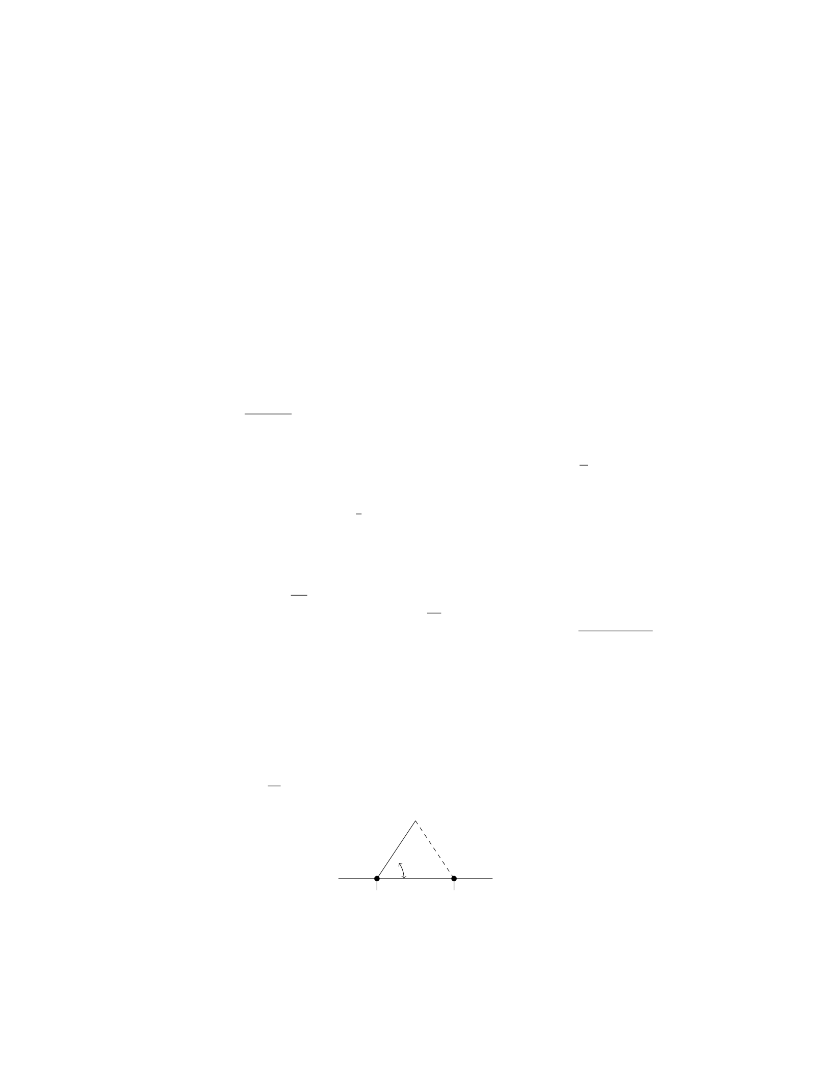
beam_system.png
6

Solution
Let’s consider the forces acting on the beam. There are three forces acting on
the beam: the force of gravity Mg acting at the center of mass of the beam, the
tension T1from the left rope, and the tension T2from the right rope.
Step 1: Set up the equations of equilibrium for the beam Since the
system is in equilibrium, the sum of torques and forces must be zero. The sum
of forces in the y-direction is zero:
T1+T2−Mg = 0
The sum of torques about any point (we choose the left end) is zero:
T2L−Mg(L/2−x)−T1x= 0
Step 2: Solve the equations simultaneously
From equation (1):
T1=Mg −T2(3)
From equation (2):
T2L−Mg(L/2−x)−T1x= 0
Substitute equation (3) into the equation above:
T2L−Mg(L/2−x)−(Mg −T2)x= 0
T2L−Mg(L/2−x)−Mgx +T2x= 0
Solving for T2:
T2L−Mg(L/2−x)−Mgx +T2x= 0
T2L−MgL/2 + Mgx −M gx +T2x= 0
T2L−MgL/2 + T2x= 0
T2(L+x) = MgL/2
T2=MgL
2(L+x)
Step 3: Calculate the tension in T1Substitute T2=Mg −T1into the
expression for T2:
Mg −T1=MgL
2(L+x)
T1=Mg −MgL
2(L+x)
T1=Mg 1−L
2(L+x)
Therefore, the tension in the left rope T1is M g 1−L
2(L+x)and the tension
in the right rope T2is MgL
2(L+x).
7
Question 8
Question
A steel rod of length 2.0 m is attached to a wall at one end and has a weight
of 400 N hanging from the other end. If Young’s modulus for steel is 2.0×10¹¹
N/m2, find the change in length of the rod. (Hint: The weight of the rod is
concentrated at the center of mass, which is 1.0 m away from the wall.)
Solution
Step 1: We first need to calculate the force of gravity acting on the steel rod.
Since the weight of the rod is being concentrated at its center of mass, the force
of gravity can be calculated as F=mg, where mis the mass of the rod and g
is the acceleration due to gravity. Given that the weight of the rod is 400 N, we
have m=400 N
9.81 m/s2≈40.73 kg. Therefore, F= 40.73 kg ×9.81 m/s2≈400 N.
Step 2: Next, we need to calculate the stress applied to the rod. As the
weight is hanging in the center of the rod, the force applied is evenly distributed
along the length. Therefore, the stress can be calculated as σ=F
A, where A
is the cross-sectional area of the rod. The cross-sectional area of the rod can
be calculated as A=πr2, where ris the radius of the rod. Since the rod is
cylindrical, the radius is r=d
2, where dis the diameter of the rod. Given that
the rod is made of steel, Young’s modulus is 2.0×10¹¹ N/m2, and the rod’s
diameter is not provided, we cannot directly calculate the cross-sectional area.
Step 3: We can relate stress (σ) to strain (ϵ) using Hooke’s Law: σ=Eϵ,
where Eis Young’s modulus and ϵis the strain. The strain in the rod can be
calculated as ϵ=∆L
L, where ∆Lis the change in length and Lis the original
length of the rod. Hence, we have ∆L=σL
E.
Step 4: Substituting the values we have calculated, we get ∆L=400 N×1.0 m
2.0×10¹¹ N/m2=
2.0×10⁻³m=2.0 mm. Therefore, the change in length of the rod is 2.0 mm.
Question 9
Question
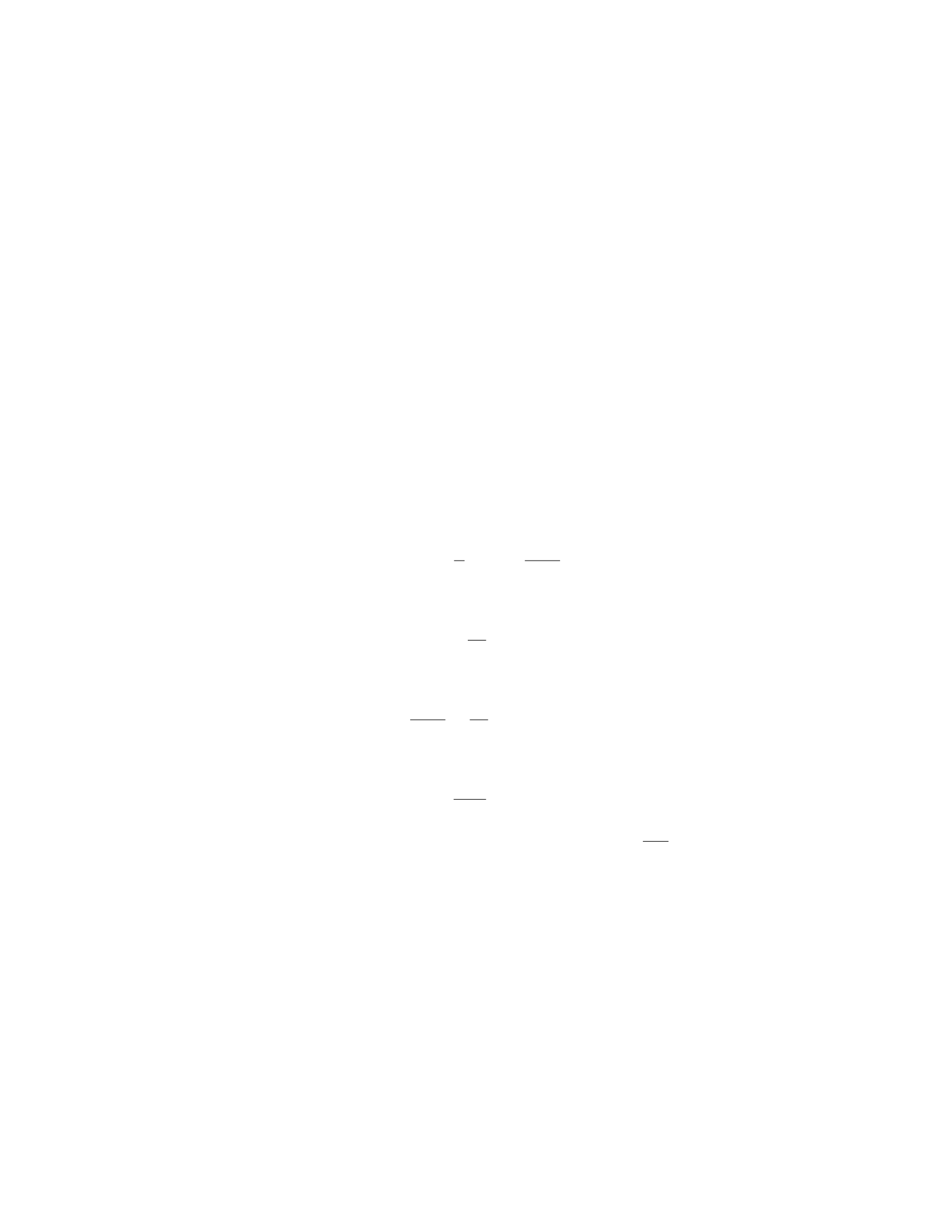
A uniform beam of length Land mass Mis resting horizontally on two sup-
ports, as shown in the diagram below. The beam is also attached to a cable
at a distance 2L
3from one end, which makes an angle θwith the horizontal.
Determine the tension in the cable as a function of θ.
θ
A B
8
Solution
Step 1: Find the forces acting on the beam. Since the beam is in equilibrium,
the sum of the forces and torques acting on the beam must add up to zero.
Let Tbe the tension in the cable, NAand NBbe the normal forces at the
supports Aand Brespectively, W=Mg be the weight of the beam, and Fhoriz
be the horizontal component of the tension.
In the vertical direction:
NA+NB−Mg = 0 ⇒NA=Mg −NB
In the horizontal direction:
Fhoriz = 0
Step 2: Determine the torque about point A. The torque about point Adue
to the weight of the beam and the tension in the cable must balance each other
out.
Torque due to the weight:
τweight =L
2·Mg =MgL
2
Torque due to the tension:
τtension =2L
3·Tsin(θ)
Setting these torques equal to each other:
MgL
2=2L
3Tsin(θ)
Step 3: Solve for the tension in the cable. Solving for T:
T=3Mg
4cot(θ)
Therefore, the tension in the cable as a function of θis T=3Mg
4cot(θ).
Question 10
Question
A cylindrical steel rod of length 2.0 m and diameter 1.0 cm hangs vertically
from the ceiling. The rod supports a weight of 100 N at its lower end. Find the
elongation of the rod. (Take Young’s modulus for steel to be 2.0×10¹¹ N/m2
and ignore the weight of the rod itself.)
9

Solution
Step 1: Calculate the cross-sectional area of the rod.
Given that the diameter of the rod is 1.0 cm, the radius ris 0.5 cm or 0.005 m.
Therefore, the cross-sectional area of the rod Ais:
A=πr2=π(0.005)2m2
Step 2: Calculate the stress in the steel rod.
The stress σis defined as the force Fapplied per unit area A:
σ=F
A=100
π(0.005)2N/m2
Step 3: Calculate the strain in the steel rod.
Using Hooke’s Law, which states that stress σis proportional to strain εby the
equation σ=Y ε, where Yis the Young’s modulus, we can solve for the strain
ε:
ε=σ
Y=100
π(0.005)2×2.0×1011
Step 4: Calculate the elongation of the rod.
The elongation ∆Lcan be found using the equation ∆L=ε×L:
∆L=100
π(0.005)2×2.0×1011 ×2.0
Therefore, the elongation of the rod is calculated to be ∆L.
Question 11
Question
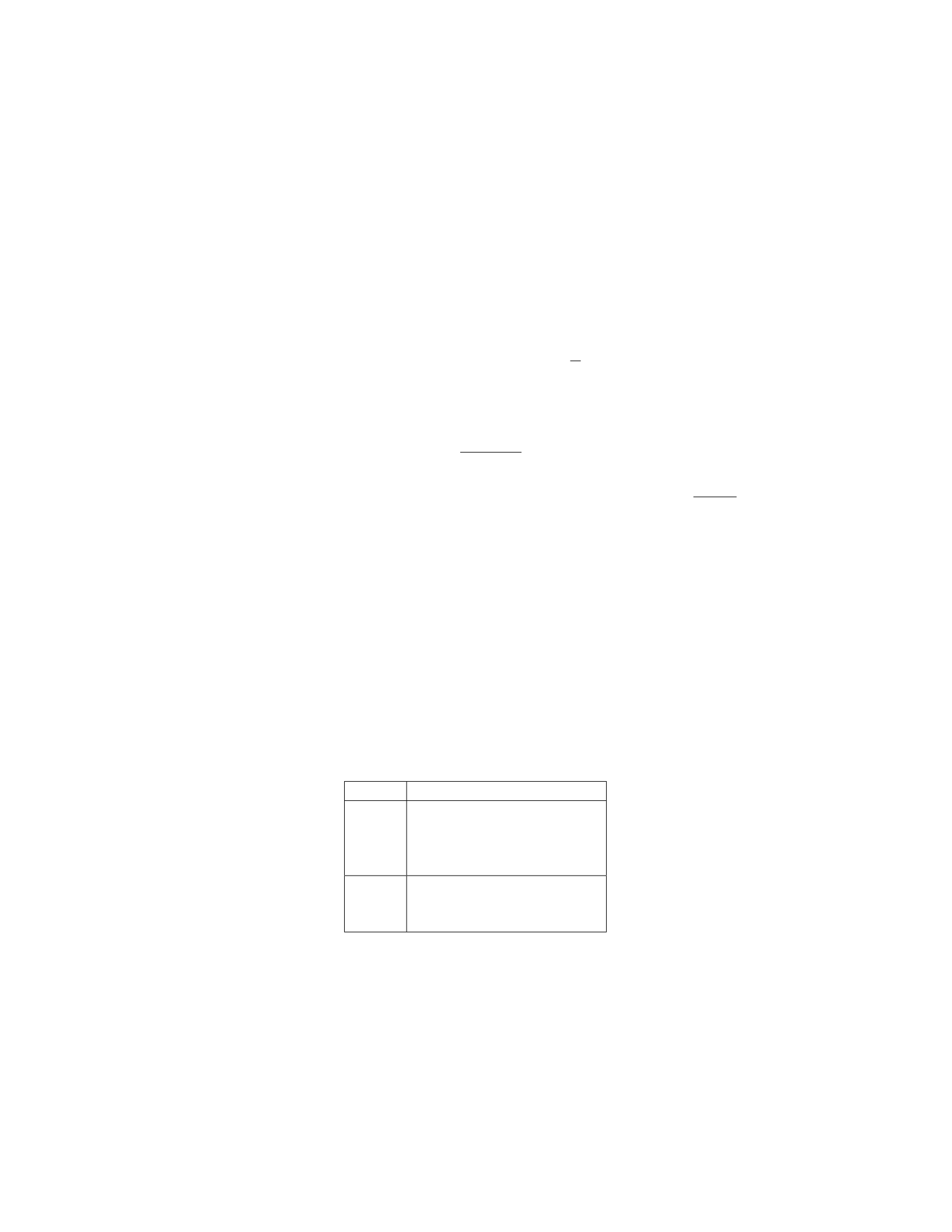
A uniform rod of length Land mass Mis hanging vertically with one end
attached to the ceiling by a hinge. A bullet of mass mand velocity vis fired
directly horizontally into the other end of the rod, where it lodges. Find the
angular speed of the rod just after the bullet lodges.
Solution
Step 1: We will start by determining the initial angular momentum of the
system. The initial angular momentum is given by the sum of the angular
momentum of the bullet and the rod:
Linitial =Lbullet +Lrod
The initial angular momentum of the bullet is:
Lbullet =m×v×L
10
Step 2: The initial angular momentum of the rod is zero since it is at rest
initially. Therefore:
Linitial =m×v×L
Step 3: After the bullet lodges in the rod, their combined mass is (M+m)
and the system rotates about the hinge. The conservation of angular momentum
gives us:
Linitial =Lfinal
m×v×L= (M+m)×ω×L
2
where ωis the angular speed of the rod just after the bullet lodges.
Step 4: Solving for ω, we find:
ω=2m×v
(M+m)
Therefore, the angular speed of the rod just after the bullet lodges is 2m×v
(M+m).
Question 12
Question
A uniform 4 kg horizontal beam is supported by two vertical ropes attached at
each end. A crate with a mass of 10 kg hangs from the middle of the beam. If
each rope makes an angle of 30 degrees with the horizontal, what is the tension
in each rope? Assume the beam is in static equilibrium.
Solution
Step 1: Draw a free-body diagram of the system. Label all the forces acting on
the beam and the crate.
Object Forces
Beam
Tension in left rope, T1
Tension in right rope, T2
Weight of beam, Wb
Normal force, N
Crate
Weight of crate, 10g
Tension in left rope, T1
Tension in right rope, T2
Step 2: Write the equations for equilibrium in the x and y directions for the
system. In the x-direction:
T2cos(30◦)−T1cos(30◦)=0
11

In the y-direction:
T1sin(30◦) + T2sin(30◦)−10g−Wb= 0
Step 3: Calculate the weight of the beam and the weight of the crate.
Wb= 4g= 40 N
10g= 10 ×9.8 = 98 N
Step 4: Substitute the known values and solve the equations simultaneously.
From the x-equation:
T2=T1
Substitute Wb, 10g, and T2=T1into the y-equation:
T1sin(30◦) + T1sin(30◦)−10 ×9.8−40 = 0
2T1sin(30◦) = 138
T1=138
2 sin(30◦)= 138
Therefore, the tension in each rope is 138 N.
Question 13
Question
A cylinder of mass mand radius ris floating in a liquid of density ρ. The top
surface of the cylinder is at a depth hbelow the liquid surface. Determine the
magnitude of the normal force exerted by the liquid on the bottom surface of
the cylinder.
Solution
Step 1: First, let’s determine the volume of the part of the cylinder submerged
in the liquid. The volume Vcan be found using the formula for the volume of
a cylinder: V=πr2h.
Step 2: The weight of the liquid displaced by the submerged part of the
cylinder is equal to the weight of the cylinder and is given by the formula
m=ρV g, where gis the acceleration due to gravity.
Step 3: The normal force exerted by the liquid on the bottom surface of
the cylinder is equal in magnitude to the weight of the liquid displaced by the
cylinder. Therefore, the normal force Fliquid =ρV g.
Step 4: Substituting the expression for Vinto the formula for the normal
force, we get Fliquid =ρπr2hg. Thus, the magnitude of the normal force exerted
by the liquid on the bottom surface of the cylinder is ρπr2hg .
12

Question 14
Question
A uniform horizontal beam of mass Mand length Lis supported by two vertical
cables attached at the ends of the beam. The tension in the left cable is given by
T1and the tension in the right cable is given by T2. If the beam is in equilibrium,
determine the tensions T1and T2in terms of M,L, and acceleration due to
gravity g.
Solution
1. Draw a free-body diagram for the beam. The forces acting on the beam
include its weight W=M g acting downwards at the beam’s center of mass, the
tension T1in the left cable acting upwards at the left end, and the tension T2
in the right cable acting upwards at the right end.
2. Since the beam is in equilibrium, the net force and net torque on the
beam are both zero.
3. Write the force balance equation in the vertical direction:
T1+T2=Mg
4. To write the torque balance equation, choose a pivot point where only
one of the cable forces will generate torque. Let’s choose the pivot at the
left end of the beam. The torque due to the tension T2about this point is
clockwise and equals T2·L. The torque due to the weight Mg about this point
is counterclockwise and equals −1
2L·Mg. The torque equation is:
T2·L−1
2L·Mg = 0
5. Solve the force balance equation for T2:
T2=Mg −T1
6. Substitute T2=Mg −T1into the torque equation:
(Mg −T1)·L−1
2L·Mg = 0
MgL −T1L−1
2MgL = 0
7. Simplify the equation:
1
2T1L=1
2MgL
T1=Mg
13

8. Finally, substitute T1=Mg back into the force balance equation:
T2=Mg −Mg = 0
Therefore, the tensions are:
T1=Mg
T2= 0
Question 15
Question
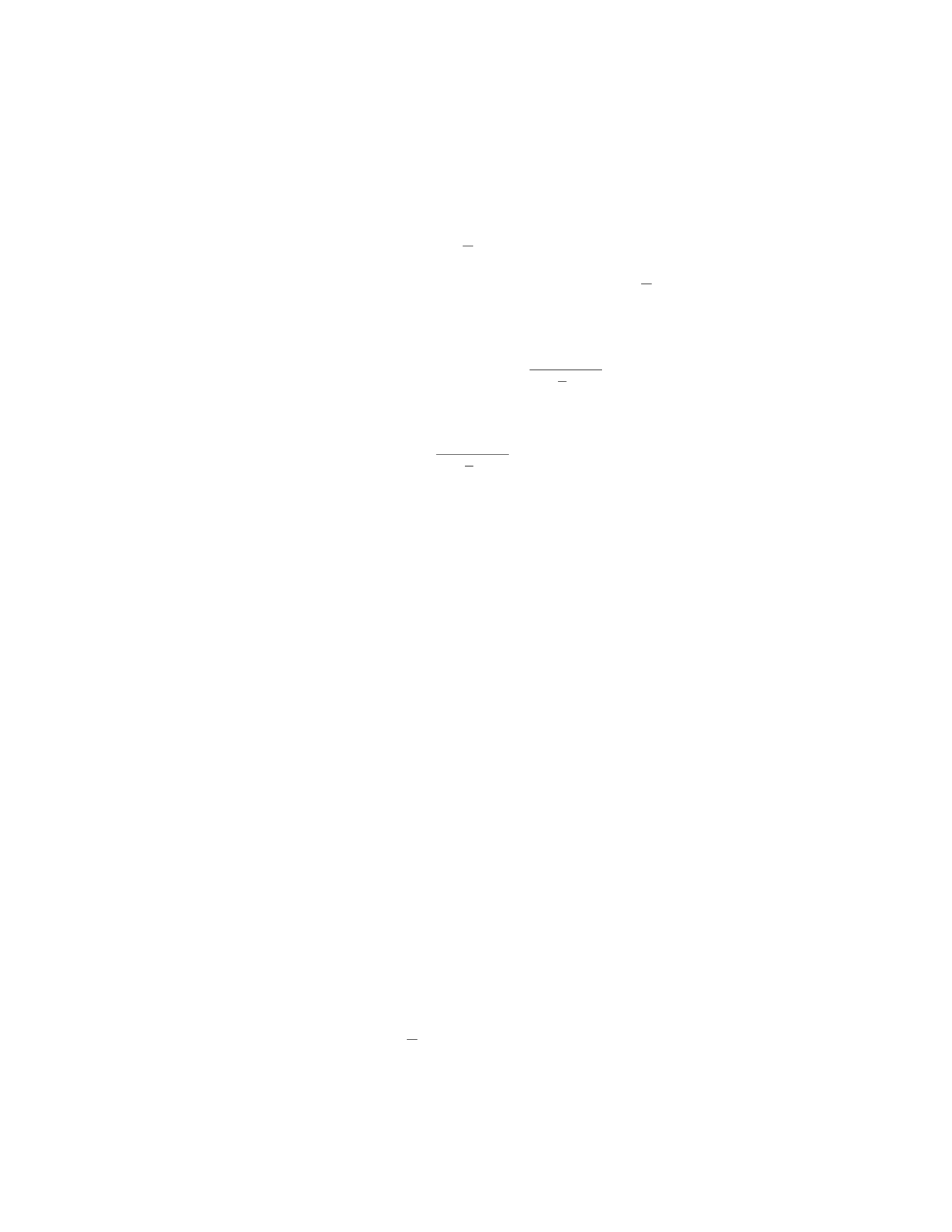
A uniform beam of length Land mass Mis supported by a pivot at one end,
with a weight Whanging from the other end. If the beam makes an angle θ
with the horizontal, determine the tension in the pivot and the force exerted by
the pivot on the beam. Assume that the beam is in equilibrium and neglect the
mass of the beam.
Solution
Step 1: First, draw a free body diagram of the beam and the forces acting on it.
Let Tbe the tension in the pivot, Nbe the normal force exerted by the pivot,
and Wbe the weight hanging from the beam. The forces can be broken down
into their x and y components:
In the xdirection: N=Tsin θ
In the ydirection: W=Mg +Tcos θ
Step 2: Since the system is in equilibrium, the sum of the torques about any
point must be zero. Let’s take torques about the pivot point. The torque due to
the weight Wis negative (since it tends to rotate the beam counterclockwise),
while the torque due to the normal force Nand the tension Tare positive
(since they tend to rotate the beam clockwise). The torque due to Wis given
by −W·L
2sin θ, and the torque due to Nis N·L. The torque equation becomes:
N·L−W·L
2sin θ= 0
Step 3: Substituting the expressions for Nand Winto the torque equation:
Tsin θ·L−(Mg +Tcos θ)·L
2sin θ= 0
14
Step 4: Solving for T, we get:
Tsin θ·L−(Mg +Tcos θ)·L
2sin θ= 0
Tsin θ·L= (Mg +Tcos θ)·L
2sin θ
2Tsin θ·L= (Mg +Tcos θ)·Lsin θ
2T=Mg +Tcos θ
T=Mg
2−L
Lcos θ
Step 5: To find N, substitute the expression for Tback into N=Tsin θ:
N=Mg
2−L
Lcos θ·sin θ
Question 16
Question
A uniform rod of length Land mass Mis supported by a pivot at one end. A
force Fis applied perpendicular to the rod at a distance xfrom the pivot. Find
the condition for the rod to be in equilibrium.
Solution
To find the condition for the rod to be in equilibrium, we need to balance the
torques acting on the rod.
Step 1: Calculate the torque due to the gravitational force on the rod. The
gravitational force acts at the center of mass, which is at a distance L/2 from
the pivot point.
The torque due to the gravitational force (τg) is given by:
τg= (L/2) ·M·g
Step 2: Calculate the torque due to the force F. The torque due to the
force Fis given by:
τF=x·F
Step 3: Set up the condition for equilibrium. For the rod to be in equilib-
rium, the net torque acting on the rod must be zero. Therefore, we have:
τnet =τg−τF= 0
Substituting in the expressions for τgand τFand setting the net torque to
zero gives: L
2·M·g−x·F= 0
15

Step 4: Solve for the condition. Solving the above equation for F, we get:
F=M·g·L
2x
Therefore, the condition for the rod to be in equilibrium is when the force
Fis equal to M·g·L
2x.
Question 17
Question
A 2 kg mass is suspended from a vertical spring, causing it to stretch 10 cm.
The spring constant is 400 N/m. Another identical mass is then added to the
first mass, causing the spring to stretch an additional 5 cm. What is the period
of oscillation for the combined system of two masses?
Solution
Step 1: Determine the total mass of the system of two masses. The mass of
each mass is 2 kg, so the total mass of the system is 2 kg + 2 kg = 4 kg.
Step 2: Calculate the total stretch in the spring. The initial stretch was 10
cm. When the second mass is added, the spring stretches an additional 5 cm,
making the total stretch 15 cm.
Step 3: Calculate the effective spring constant of the two-mass system. The
spring constant for each mass is 400 N/m. The effective spring constant for the
two-mass system is calculated as:
keff =k1·k2
k1+k2
keff =400 N/m ×400 N/m
400 N/m + 400 N/m
keff =160000 N2/m2
800 N/m = 200 N/m
Step 4: Calculate the period of oscillation for the two-mass system. The
period of oscillation for a mass-spring system is given by:
T= 2πrm
k
Where mis the total mass and kis the effective spring constant.
T= 2πs4 kg
200 N/m
T= 2πp0.02 s2/m=0.282 s
Therefore, the period of oscillation for the combined system of two masses
is 0.282 seconds.
16

Question 18
Question
A uniform horizontal shelf of length Land weight Wis supported by two vertical
springs at its ends, each with spring constant k. A block of weight wis placed
on the shelf, a distance xfrom the left end. If the springs are to support the
shelf and block without compression or extension, determine the force constant
kof the springs in terms of the given parameters.
Solution
1. Draw a free-body diagram of the system. Label the forces acting on the shelf
and block, including the normal forces from the springs and the weight of the
shelf and block.
2. Write out the equilibrium equations in the vertical and horizontal direc-
tions. For equilibrium in the vertical direction, the sum of the vertical forces
must equal zero. For equilibrium in the horizontal direction, the sum of the
horizontal forces must equal zero.
3. In the vertical direction, the forces acting on the shelf and block are the
weight of the block w, the weight of the shelf W, and the normal forces from
the two springs. Set up the equation for equilibrium in the vertical direction.
4. In the horizontal direction, the only force acting on the block is the
normal force from the spring on the left, and the only force acting on the shelf
is the normal force from the spring on the right. Write out the equation for
equilibrium in the horizontal direction.
5. Knowing that the sum of the forces is zero, solve the system of equations
to find the normal forces from the springs in terms of the given parameters.
6. Express the normal forces in terms of k,x,L,w, and W. Use these
expressions to find the force constant kin terms of the given parameters.
Therefore, the force constant kof the springs should be 4wx
L(2L−x).
Question 19
Question
A metal rod of length Lis suspended vertically from one end. A weight W
is attached to the other end of the rod, causing it to stretch by an amount
∆L. The rod has a uniform cross-sectional area Aand a Young’s modulus Y.
Calculate the stress and strain in the rod.
Solution
Step 1: To calculate the stress (σ) in the rod, we can use the formula for stress:
σ=F
A
17

where Fis the force causing the stress and Ais the cross-sectional area of the
rod. In this case, the force causing the stress is the weight W, so F=W.
Therefore, we have:
σ=W
A
Step 2: Next, let’s calculate the strain (ϵ) in the rod using Hooke’s Law.
Hooke’s Law states that the strain in a material is directly proportional to the
stress applied to it. Therefore, we have:
ϵ=∆L
L
Step 3: Substituting the given values into the formulas, we have:
σ=W
A
ϵ=∆L
L
Step 4: We can also express stress in terms of Young’s modulus and strain:
σ=Y·ϵ
Substitute in the expressions for stress and strain:
W
A=Y·∆L
L
Step 5: Now, we can solve for stress and strain:
σ=W
A
ϵ=∆L
L
Therefore, the stress in the rod is W
Aand the strain in the rod is ∆L
L.
Question 20
Question
A uniform beam of mass mand length Lis supported by a pivot at one end
and a rope attached 3/4 of its length from the other end. A weight Wis hung
from the end of the beam. If the beam is in equilibrium, determine the tension
in the rope.
18

Solution
1. Draw a free-body diagram of the beam. Label the pivot point as A, the
attachment point of the rope as B, the location of the weight Was C, and the
center of mass of the beam as G.
2. Apply the rotational equilibrium condition:
Xτ= 0
The torque at point Adue to the weight and tension is equal to 0 since the
beam is in rotational equilibrium:
τA= 0
3. Find the torque at point Bdue to the weight and tension:
τB=WL
4−T3L
4
4. The torque at point Bis also equal to 0 since the beam is in rotational
equilibrium:
τB= 0
5. Set the torque equation equal to 0 and solve for the tension T:
WL
4−T3L
4= 0
T=1
3W
Therefore, the tension in the rope is 1
3W.
Question 21
Question
A uniform beam of length Land mass Mrests horizontally on two supports, one
at each end. A block of mass mis placed a distance xfrom the left end of the
beam. If the beam just begins to tip when the block is placed on it, determine
the coefficient of static friction between the beam and the left support. Assume
the block does not slide on the beam.
Solution
Step 1: Draw a free-body diagram of the beam and block system. The forces
acting on the system are the gravitational forces mg and Mg acting on the block
and beam respectively, the normal forces N1and N2acting at the supports, and
19

the frictional force facting between the beam and the left support due to the
impending tipping motion.
Step 2: Write out the equilibrium conditions for the beam and block system
in the vertical and rotational directions. In the vertical direction: - N1+N2=
mg +Mg In the rotational direction about the point where the left support is:
-MgL/2−f·x=m·g·x
Step 3: Express the frictional force in terms of the coefficient of static friction.
The maximum static friction force that could act at the left support without
tipping the beam is fmax =µN1=µ(mg +Mg).
Step 4: Substitute fmax into the equilibrium condition for rotation to get an
expression in terms of µ: - µ(mg +Mg)·x=M·g·L/2
Step 5: Solve for the coefficient of static friction µ: - µ=M gL
2x(mg+M g)
Question 22
Question
A uniform wooden beam of length Land mass Mis supported by a rope attached
at a distance xfrom one end. If the beam makes an angle θwith the horizontal,
find the tension in the rope.
Solution
Step 1: We begin by drawing a free body diagram of the beam. Let Tbe
the tension in the rope, Rbe the force exerted by the pivot point, mg be the
gravitational force acting at the center of the beam, and Nbe the normal force
exerted by the pivot point on the beam.
Step 2: Resolve the gravitational force into components parallel and per-
pendicular to the beam. The component parallel to the beam will balance the
tension in the rope while the component perpendicular to the beam will balance
the normal force.
Step 3: Summing the forces vertically and horizontally, we get: Vertically:
Tcos θ=mg Horizontally: Tsin θ=R
Step 4: The torque about the pivot point is zero since the beam is in equilib-
rium. The torque due to the tension and the weight of the beam must balance
each other. Taking torque about the pivot point: Tsin θ·x=1
2L·M·g·cos θ
Step 5: From Step 3, we can express Rin terms of T:Tsin θ=RSubstitute
this into the torque equation: Tsin θ·x=1
2L·M·g·cos θ
Step 6: Solve the torque equation for Tto find the tension in the rope:
T=1
2L·M·g·cos θ/(xsin θ)T=1
2M·g·L·cos θ/x
Therefore, the tension in the rope is 1
2M·g·L·cos θ/x.
20

Question 23
Question
A uniform wooden beam of length Land mass Mis supported by a pivot at
one end. A ball of mass mis attached to the beam at a distance L
3from the
pivot, as shown in the diagram below. If the beam is in equilibrium and the
pivot exerts no force on the beam other than a vertical force to hold it up, find
the tension in the wire holding the ball in place.
[Diagram not shown]
Solution
1. Draw a free-body diagram of the beam. The forces acting on the beam are
its weight M g, the tension in the wire T, and the normal force Nfrom the
pivot. 2. Choose a coordinate system where the positive y-axis points upwards.
3. Write out the force equilibrium equations:
XFx= 0 and XFy= 0
4. Resolve forces parallel and perpendicular to the beam.
Parallel to beam: Tsin θ=Mg L
2(Equation 1)
Perpendicular to beam: N−Tcos θ=Mg L
3(Equation 2)
5. To find T, first eliminate θby dividing Equation 2 by Equation 1:
N−Tcos θ
Tsin θ=Mg L
3
Mg L
2
N
Tsin θ−Tcos θ
Tsin θ=1
32
1
N
Tsin θ−cot θ=2
3
6. Recognize that cot θ=1
tan θ=1
Tcos θ
Mg(L
2)
=Mg(L
2)
Tcos θ. Substitute this into the
expression from step 5:
N
Tsin θ−Mg L
2
Tcos θ=2
3
7. Rearrange the equation to solve for T:
N
T−Mg L
2
T=2
3sin θ
21

N
T=Mg L
2
T+2
3sin θ
T=N
Mg(L
2)
T+2
3sin θ
8. Since the beam is in equilibrium, the sum of vertical forces must be zero:
N=Mg L
3. Substitute this into the equation for T:
T=Mg L
3
Mg(L
2)
T+2
3sin θ
9. The tension in the wire holding the ball in place, T, can be found by solving
the above equation.
Question 24
Question
A uniform beam of length Land mass Mis supported at a pivot point located
at a distance afrom one end. A force Fis applied at the opposite end of the
beam. If the beam is in equilibrium, determine the tension in the beam at a
distance bfrom the pivot point.
Solution
To solve this problem, we will use the condition for rotational equilibrium: the
sum of the torques acting on the beam must be zero.
Step 1: Identify the torques The torque due to the force Fabout the
pivot point can be calculated as τ=F(L−b). The torque due to the gravita-
tional force acting on the beam itself can be calculated as τ′=Mg L
2−b.
Step 2: Set up the equilibrium condition In rotational equilibrium,
the sum of the torques must be zero. Thus, we have:
τ+τ′= 0
F(L−b) + Mg L
2−b= 0
Step 3: Solve for the tension Solving the equation above for F, we get:
F=−MgL
2+Mgb
Therefore, the tension in the beam at a distance bfrom the pivot point is
−MgL
2+Mgb.
22

Question 25
Question
A uniform beam of length Land mass Mis supported at two points: one-third
of the way from the left end, with a support force F1, and two-thirds of the
way from the left end, with a support force F2. If the beam is horizontal and in
equilibrium, determine the magnitudes of F1and F2in terms of M,L, and g.
Solution
Step 1: Draw a free-body diagram of the beam with the support forces F1and
F2. Step 2: Write down the force balance equations in the xand ydirections.
The beam is in equilibrium, so the net force and net torque must be zero. In
the xdirection, the equation is:
F1+F2= 0
In the ydirection, the equation is:
Mg −F1−F2= 0
Step 3: Solve the system of equations. From the xdirection equation, we get
F2=−F1. Substituting this into the ydirection equation gives:
Mg −F1−(−F1) = 0
Mg −2F1= 0
F1=Mg
2
So, F1=Mg
2. Step 4: Calculate F2using the relation F2=−F1. Substituting
F1=Mg
2into this relation gives:
F2=−Mg
2
Therefore, F2=−Mg
2(Note the negative sign indicates the direction of the
force). Thus, the magnitudes of F1and F2in terms of M,L, and gare F1=M g
2
and F2=−Mg
2.
Question 26
Question
A uniform rod of length Land mass Mis pivoted at one end and is in equilibrium
at an angle θwith the horizontal. The free end of the rod is attached to a wall
by a string, making an angle ϕwith the horizontal. If the tension in the string
is T, determine the distance xto the point where the rod is in contact with the
wall.
23

Solution
Step 1: Draw a free body diagram of the rod. Mark all forces acting on the rod.
Step 2: Resolve the forces into their horizontal and vertical components.
The forces acting on the rod are the weight M g, the tension T, and the normal
force Nfrom the wall.
Step 3: Write the equilibrium conditions in the horizontal and vertical di-
rections. Equilibrium in the horizontal direction gives Ncos ϕ=Tsin θ.
Step 4: Equilibrium in the vertical direction gives Nsin ϕ=M g −Tcos θ.
Step 5: Solve for the normal force Nin terms of Tand the angles: N=
Tsin θ
cos ϕ.
Step 6: Substitute the expression for Ninto the vertical equilibrium equation
and solve for the tension T:T=Mg
sin ϕ+cos θ.
Step 7: To find the distance x, use the fact that the torque about the pivot
point must be zero. Integrate the torque contributions of the weight and tension
force along the rod to find x.
Step 8: Integrating the torque from the weight of the rod: Rx
0
(M/L)gx
2dx =
Mg
2Lx2.
Step 9: Integrating the torque from the tension T:RL
xT x cos θdx =Tcos θL2
2−x2
2.
Step 10: Set the total torque equal to zero and solve for x:Mg
2Lx2=
Tcos θL2
2−x2
2.
Step 11: Substitute the expression for Tfrom step 6 into the torque equation
and solve for x. The final expression for xwill be in terms of L,M,g,θ, and ϕ.
Question 27
Question
A rectangular block of wood of mass 2.5 kg and dimensions 20 cm×16 cm×8 cm
floats in water with the 20 cm side horizontal. Find the distance ”d” below
the water surface where the block is in equilibrium. The density of water is
1000 kg/m3and the acceleration due to gravity is 9.81 m/s2.
Solution
Step 1: Calculate the volume of the block. The volume of the block can be
calculated using the formula:
V=l×w×h
where l= 20 cm, w= 16 cm, and h= 8 cm.
Converting all measurements to meters:
V= 0.20 m ×0.16 m ×0.08 m = 0.00256 m3
24

Step 2: Calculate the weight of the block. The weight of the block is given
by:
W=m×g
where m= 2.5 kg and g= 9.81 m/s2.
W= 2.5 kg ×9.81 m/s2= 24.525 N
Step 3: Calculate the buoyant force acting on the block. The buoyant force
is given by:
Fb=ρ×g×V
where ρ= 1000 kg/m3(density of water) and V= 0.00256 m3.
Fb= 1000 kg/m3×9.81 m/s2×0.00256 m3= 25.1136 N
Step 4: Calculate the distance ”d” below the water surface. At equilibrium,
the weight of the block is equal to the buoyant force acting on it:
W=Fb
24.525 N = 25.1136 N
Let hbe the depth submerged
Vsubmerged =l×w×h
0.20 m ×0.16 m ×h= 0.00256 m3
h=0.00256 m3
0.20 m ×0.16 m =0.00256 m3
0.032 m2= 0.08 m
Therefore, the block is in equilibrium at a distance of 8 cm below the water
surface.
Question 28
Question
A uniform rod of length Land mass Mis supported by a pivot at one end, as
shown in the figure below. A block of mass mis attached to the free end of
the rod. The system is in equilibrium, with the rod making an angle θwith the
vertical. Find an expression for the tension Tin the rod and the normal force
Nexerted by the pivot on the rod in terms of m,M,L,g, and θ.
rod_pivot.png
25
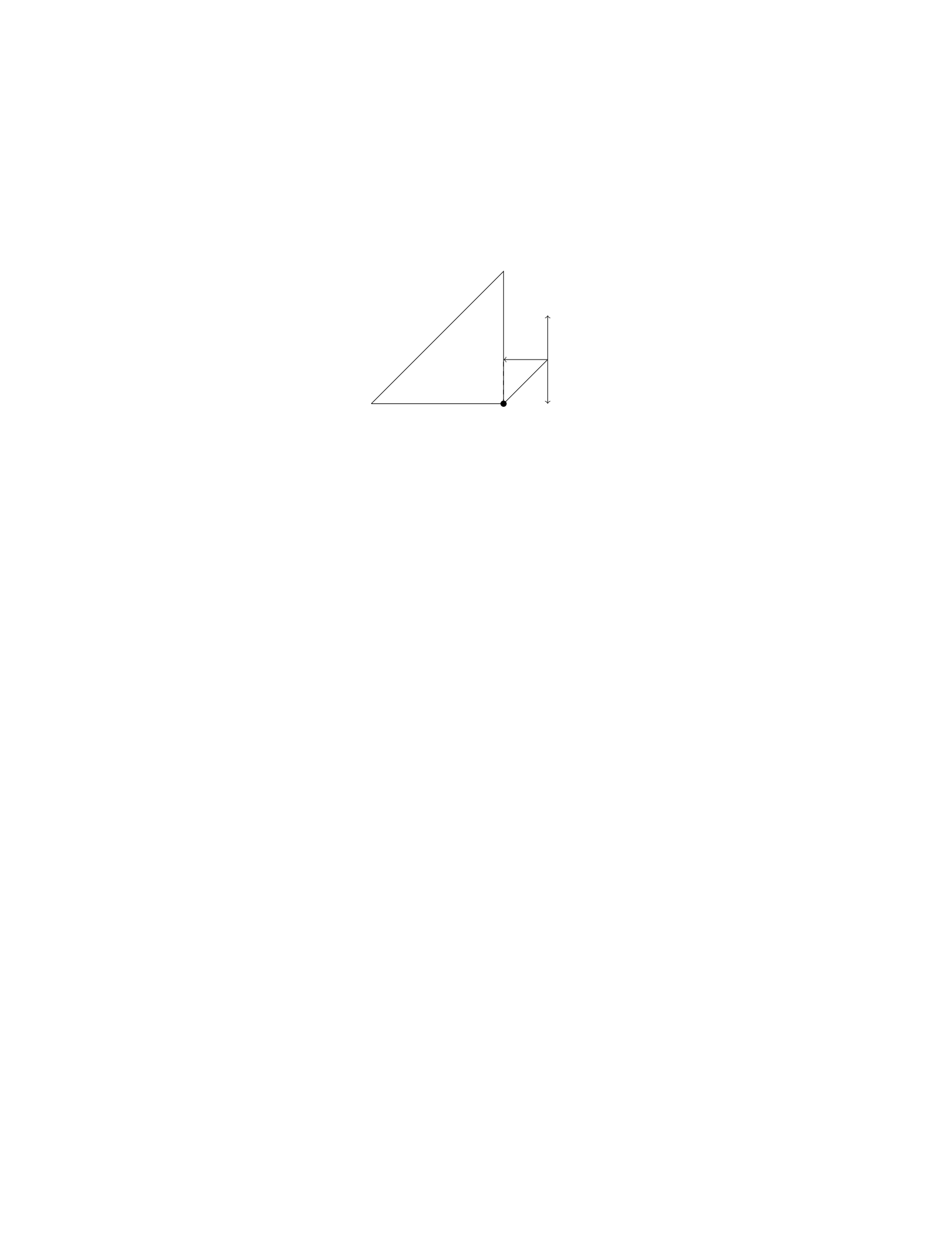
Solution
Step 1: Begin by drawing a free body diagram of the block and the forces acting
on it.
Pivot
N
Tmg
ℓ θ
Step 2: Write out the equations of equilibrium. In the vertical direction:
N+Tsin(θ)−mg = 0
In the horizontal direction:
Tcos(θ) = 0
Step 3: Solve the horizontal equation Tcos(θ) = 0 to find T= 0. This
means there is no horizontal acceleration, which is expected since the block is
not moving horizontally.
Step 4: Substitute T= 0 into the vertical equilibrium equation:
N+ 0 −mg = 0
Thus, N=mg.
Therefore, the tension in the rod is T= 0 and the normal force exerted by
the pivot on the rod is N=mg.
Question 29
Question
A solid cylindrical rod of length Land radius Ris hanging vertically from a
ceiling. A weight Wis attached to the free end of the rod. The rod has a
uniform density ρand Young’s modulus Y. Determine the elongation of the rod
due to the weight attached to it.
Solution
Step 1: First, we will determine the mass of the rod. The mass of the rod can
be calculated as:
m=ρ·V
26

where Vis the volume of the rod. The volume of a solid cylinder with radius
Rand length Lis given by:
V=πR2L
Step 2: Substituting Vinto the equation for mass, we have:
m=ρ·πR2L
Step 3: Next, we will calculate the force due to gravity acting on the rod.
The force acting on the rod is equal to the weight of the rod plus the weight
attached to it:
F=mg =ρ·πR2L·g
Step 4: The stress due to the weight is given by:
σ=F
A
where Ais the cross-sectional area of the rod. The cross-sectional area of a
cylinder is A=πR2.
Step 5: Substituting the values of Fand Ainto the equation for stress, we
get:
σ=ρ·πR2L·g
πR2
Step 6: Using Hooke’s Law, the stress is related to the strain by:
σ=Y·ϵ
where ϵis the strain.
Step 7: Solving for ϵ, we find:
ϵ=ρ·πR2L·g
Y πR2
Step 8: The elongation ∆Lof the rod is related to the original length Land
the strain ϵby:
∆L=L·ϵ
Step 9: Substituting the value of ϵinto the equation for elongation, we have:
∆L=L·ρ·πR2L·g
Y πR2
Question 30
Question
A uniform beam of length Land mass Mis attached to a wall by a hinge at
one end. The beam makes an angle θwith the horizontal and is supported by
a cable making an angle ϕwith the beam, as shown in the figure below.
27
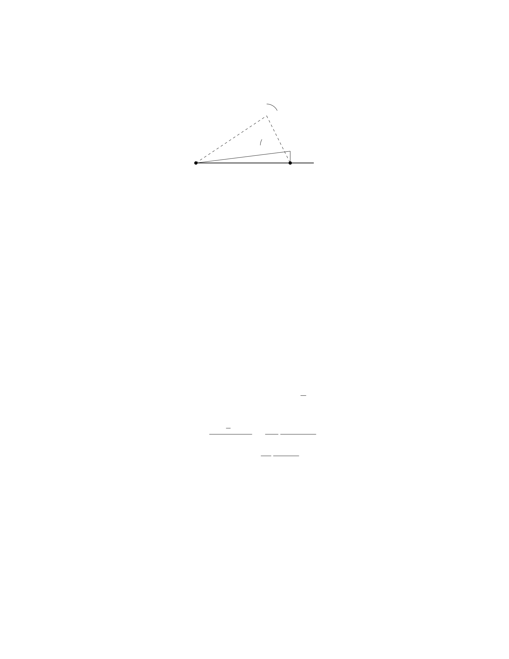
θ
ϕ
O A
Determine the tension in the cable.
Solution
Step 1: Summing the forces in the xdirection and ydirection, we have:
XFx=Tsin ϕ−0 = 0 (since the beam is in equilibrium)
XFy=Tcos ϕ−Mg = 0
Step 2: Solving the equation PFx= 0 for T, we get:
Tsin ϕ= 0 =⇒T= 0
Step 3: Substituting T= 0 into PFy= 0, we find:
0 cos ϕ−Mg = 0 =⇒Mg = 0
Step 4: This implies that M= 0, which is not a realistic scenario. Therefore,
the tension in the cable must be non-zero.
Step 5: We realize that Tcannot be solved using the forces in the xand
ydirections since the beam is not in equilibrium. To solve for T, we need to
incorporate the torque about point O.
Step 6: The torque equation about point O is given by:
Xτ= 0 = T L sin(ϕ−θ)−Mg L
2cos θ
Step 7: Solving for T, we find:
T=Mg L
2cos θ
Lsin(ϕ−θ)=Mg
2
cos θ
sin(ϕ−θ)
Therefore, the tension in the cable is Mg
2
cos θ
sin(ϕ−θ).
Question 31
Question
A uniform rod of length Land mass Mis held horizontally with one end against
a vertical wall. A massless string is attached to the other end of the rod and
is pulled horizontally by a force Fin the direction perpendicular to the rod. If
the coefficient of static friction between the wall and the rod is µs, determine
the maximum force Fmax that can be applied before the rod starts to slip.
28

Solution
Step 1: Draw the Free Body Diagram (FBD) for the rod.
Step 2: Analyze the forces acting on the rod. - The forces acting on the
rod are the tension in the string (T), the gravitational force (Mg) acting on
the center of mass, the normal force (N) exerted by the wall on the end of the
rod, the frictional force (fs) exerted by the wall on the end of the rod, and the
applied force F.
Step 3: Write the equations for equilibrium in the vertical and horizontal
directions. In the vertical direction: N−M g = 0
In the horizontal direction: T+fs+F= 0
Step 4: Determine the expressions for the tension T, the frictional force fs,
and the normal force N.
Step 5: Express the frictional force fsin terms of the coefficient of static
friction µsand the normal force N:fs=µsN
Step 6: Substitute the expressions for Tand fsalong with N=M g into
the equation for equilibrium in the horizontal direction, and solve for Fmax.
−T−µsMg +F= 0
Step 7: Solve for the maximum force Fmax:Fmax =T+µsMg
Step 8: Express the tension Tin terms of Fmax and solve for Fmax:Fmax =
2µsMg
Question 32
Question
A uniform rod of length Land mass Mis suspended horizontally by two vertical
wires attached at each end of the rod. If each wire makes an angle θwith the
vertical, find the tension in each wire.
Solution
Let’s denote the tension in each wire as T. We’ll start by drawing a free-body
diagram of the rod.
Step 1: Draw a free-body diagram of the rod.
The forces acting on the rod are its weight Wacting downwards (with mag-
nitude Mg), and the tensions Tacting in the upward direction at each end of
the rod. The angles between the tension forces and the horizontal are both θ.
Step 2: Resolve forces along the vertical and horizontal directions.
Resolving forces along the vertical direction:
2Tcos(θ) = Mg or T=Mg
2 cos(θ)
Step 3: Simplify the expression for tension in each wire.
Thus, the tension in each wire is T=M g
2 cos(θ).
29

Question 33
Question
A uniform rod of length Land mass Mis lying on a frictionless horizontal
surface. The rod is pivoted about a point Plocated at one end of the rod. A
point-like object with mass mis placed a distance xfrom the pivot point on the
rod. The system is in equilibrium.
If the rod is moved such that the hanging object is now a distance yfrom the
pivot point, determine the new angle θthat the rod makes with the horizontal.
Solution
1. We will begin by analyzing the forces acting on the system when the object
is placed at a distance xfrom the pivot point:
The forces acting on the mass mare: - The force of gravity, with magnitude
m·g, acting downward. - The normal force from the rod, with a vertical
component equal to Ncos θpointing upward and a horizontal component equal
to Nsin θpointing to the left. - The tension force Tin the rod, with a horizontal
component equal to Tcos θpointing to the right and a vertical component equal
to Tsin θpointing upward.
2. Since the system is in equilibrium, the sum of the forces in the xand y
directions must be zero:
Sum of forces in the xdirection:
Tcos θ=m·g
Sum of forces in the ydirection:
Ncos θ=m·g
3. Next, we will analyze the forces acting on the system when the object is
placed at a distance yfrom the pivot point:
The forces acting on the mass mare: - The force of gravity, with magnitude
m·g, acting downward. - The normal force from the rod, with a vertical
component equal to Ncos θpointing upward and a horizontal component equal
to Nsin θpointing to the left. - The tension force Tin the rod, with a horizontal
component equal to Tcos θpointing to the right and a vertical component equal
to Tsin θpointing upward.
4. Again, since the system is in equilibrium, the sum of the forces in the x
and ydirections must be zero:
Sum of forces in the xdirection:
Tcos θ=m·g
Sum of forces in the ydirection:
Ncos θ=m·g
30

5. Now, let’s find the relationship between xand y:
For the initial position:
x=Lcos θ
For the final position:
y=Lcos θ
6. Equating xand y, we have:
Lcos θ=Lcos θ
7. Therefore, the angle θremains the same when the object is moved from
a distance xto a distance yfrom the pivot point.
Question 34
Question
A 2-meter long uniform beam with a weight of 400 N is supported by a cable
attached 1.2 meters from one end of the beam. A 600 N person stands 0.8
meters from the same end. What is the tension in the cable?
Solution
Step 1: Calculate the torques about the point where the cable is attached. Let’s
choose the clockwise direction as positive. The torque due to the person at one
end of the beam is given by:
Torqueperson =−600 N ×0.8 m = −480 Nm
The torque due to the weight of the beam is given by:
Torquebeam weight =−400 N ×2 m = −800 Nm
The torque due to the tension in the cable can be calculated as follows: Let’s
denote the tension in the cable as T. The distance of the cable attachment
point from the pivot is 1.2 meters. This contributes to the overall torque in the
counter-clockwise direction:
Torquetension =T×1.2 m
Since the beam is in equilibrium, the sum of torques must equal zero:
XTorques = Torqueperson + Torquebeam weight + Torquetension = 0
−480 Nm −800 Nm + T×1.2 m = 0
Step 2: Solve for the tension in the cable.
T×1.2 m = 1280 Nm
31

T=1280 Nm
1.2 m
T= 1066.67 N
Therefore, the tension in the cable supporting the beam is 1066.67 N.
Question 35
Question
A uniform beam of length 4.0 m and mass 60 kg is supported by a rope attached
to its end. A 120 kg mass is placed 1.0 m from the end of the beam, causing the
beam to be in rotational equilibrium. Determine the tension in the rope and
the force exerted by the pivot on the beam.
Solution
Step 1: Set up the free-body diagram for the beam. The forces acting on the
beam are: - The weight of the beam acting at its center of mass ( L
2from the
pivot) - The tension in the rope acting vertically upwards at the end of the
beam - The weight of the 120 kg mass acting 1m from the end of the beam -
The force exerted by the pivot at the left end of the beam
Step 2: Write down the equilibrium condition for the beam. The sum of
the torques acting on the beam must be zero. Taking the pivot as the point of
rotation, we have:
Xτ= 0
T·4.0−60 ·9.8·4.0
2−120 ·9.8·1=0
Step 3: Solve for the tension in the rope.
4T−60 ·9.8·2 = 120 ·9.8
T=120 ·9.8 + 60 ·9.8·2
4
T=1176
2
T= 588 N
Step 4: Solve for the force exerted by the pivot on the beam. The sum of
the forces in the vertical direction must be zero.
Fpivot −60 ·9.8−120 ·9.8=0
Fpivot = 60 ·9.8 + 120 ·9.8
Fpivot = 1764 N
Therefore, the tension in the rope is 588 N and the force exerted by the pivot
on the beam is 1764 N.
32

