


PHYS 231 - UNIVERSITY PHYSICS I
- Equilibrium and Elasticity
Question Bank - Set 6
Liberty University
Question 1
Question
A block of mass mis placed on an inclined plane with angle θ. The coefficient of
static friction between the block and the plane is µs. Determine the minimum
angle θat which the block will remain at rest on the plane.
Solution
Step 1: Draw a free-body diagram of the block on the inclined plane. The forces
acting on the block are the gravitational force (mg) acting vertically downward,
the normal force (N) acting perpendicular to the plane, the force of static
friction (fs) acting parallel to the plane and opposing the impending motion,
and the component of the gravitational force parallel to the plane (mg sin θ).
Step 2: Write the equation for equilibrium in the direction perpendicular to the
plane:
N−mg cos θ= 0
Step 3: Write the equation for equilibrium in the direction parallel to the plane:
fs−mg sin θ= 0
Step 4: Since the block is on the verge of moving, the maximum force of static
friction can be written as fs=µsN. Step 5: Substitute N=mg cos θinto the
equation fs=µsNto get:
µsmg cos θ=mg sin θ
Step 6: Solve for θ:
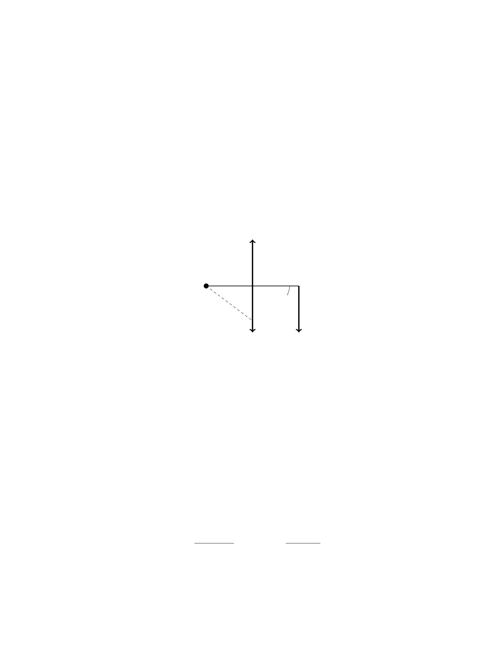
µscos θ= sin θ

tan θ=µs
Step 7: The minimum angle θat which the block will remain at rest on the
plane is:
θ= tan−1(µs)
Question 2
Question
A uniform bar of length Land mass Mis supported by two vertical cables
attached to its ends. If the left cable is at a distance L
3from the left end, and
the right cable is at a distance 2L
3from the left end, what is the tension in each
cable? Assume the bar is in equilibrium.
Solution
Step 1: Draw a Free Body Diagram (FBD) of the bar and identify the forces
acting on it. Let’s denote the tension in the left cable as T1and the tension
in the right cable as T2. Step 2: Resolve the forces in the vertical direction.
The sum of the forces in the vertical direction must be zero since the bar is in
equilibrium. Step 3: For equilibrium in the vertical direction, the sum of the
forces must be zero:
T1+T2=Mg
Step 4: Next, consider the torques acting on the bar around a pivot point at
the left end. To keep the bar in equilibrium, the net torque must be zero. Step
5: The torque (τ) due to T1is given by τ1=T1·L
3, and the torque due to T2
is given by τ2=−T2·2L
3(negative because it creates a clockwise torque). Step
6: The net torque must be zero:
T1·L
3−T2·2L
3= 0
Step 7: Solve the above two equations simultaneously to find T1and T2.
This system of equations can be simplified to find T1and T2:
T1+T2=Mg
T1·L
3−T2·2L
3= 0
Solving these equations gives:
T1=2
3Mg
T2=1
3Mg
Therefore, the tension in the left cable is 2
3Mg and the tension in the right
cable is 1
3Mg.
2
Question 3
Question
A uniform beam of length Land mass Mis supported by a pivot at its midpoint.
A block of mass mis attached to one end of the beam. The system is in
equilibrium, with the beam making an angle θwith the horizontal. Assuming
the beam is massless, determine the tension in the beam at the pivot point.
Solution
Step 1: First, draw a free-body diagram of the forces acting on the entire system.
The forces involved are: 1. The weight of the beam, acting downward at its
center of mass. 2. The weight of the block, acting downward at its position. 3.
The tension in the beam at the pivot point, acting upwards along the beam. 4.
The normal force at the pivot point, acting perpendicular to the beam.
Step 2: Write out the force equations for the system in equilibrium, in both
the vertical and horizontal directions. In the vertical direction: PFy= 0
Tcos(θ)−Mg
2−mg = 0, where Tis the tension at the pivot point, Mg is the
weight of the beam, and mg is the weight of the block.
Step 3: Solve the force equation in the vertical direction for the tension T
in terms of m,M,g, and θ.Tcos(θ) = Mg
2+mg,T=M g
2 cos(θ)+mg
cos(θ).
Therefore, the tension in the beam at the pivot point is Mg
2 cos(θ)+mg
cos(θ).
Question 4
Question
A block of mass mis placed on a ramp inclined at an angle θwith respect to
the horizontal. The coefficient of static friction between the block and the ramp
is µs. Determine the minimum angle θ0at which the block will remain at rest
on the ramp.
Solution
Step 1: Begin by drawing a free-body diagram of the forces acting on the block.
Step 2: Identify the forces acting on the block. These include the gravitational
force (mg) acting vertically downward, the normal force (N) acting perpendicu-
lar to the surface of the ramp, and the static frictional force (fs) acting parallel
to the surface of the ramp in the direction opposing motion. Step 3: Break
the gravitational force into components parallel and perpendicular to the ramp.
The component parallel to the ramp is mg sin(θ) and the component perpen-
dicular to the ramp is mg cos(θ). Step 4: Write the equilibrium condition in
the direction perpendicular to the ramp: N=mg cos(θ). Step 5: Write the
equilibrium condition parallel to the ramp: fs=mg sin(θ). Step 6: Determine
the maximum static frictional force using the relationship fs≤µsN. Substitute
3

N=mg cos(θ) into the inequality to get fs≤µsmg cos(θ). Step 7: Equate fs
and mg sin(θ) to find the angle at which the block will start moving. Thus,
mg sin(θ0) = µsmg cos(θ0). Simplify the equation to find θ0.
Question 5
Question
A uniform rod of length Land mass Mis placed horizontally on two supports,
one at each end. A weight Wis hung from a point on the rod that is a distance
2
3Lfrom one end. Find the magnitude and direction of the force each support
exerts on the rod.
Solution
Step 1: Draw a free-body diagram of the rod.
Step 2: Apply the condition for rotational equilibrium. The sum of the
torques about any point must be zero.
Let’s choose the point where the left support exerts a force on the rod to find
the unknown forces. Taking counterclockwise torques as positive, the torques
about the left support are:
τleft =−2
3L·W+L
2·Mg
Setting this equal to zero gives:
−2
3L·W+L
2·Mg = 0
Step 3: Solve for the weight Win terms of Mand g.
2
3W=1
2Mg
W=3
4Mg
Step 4: With Wfound, we can determine the forces exerted by each support
using the condition of vertical equilibrium:
Fleft +Fright =Mg +W
Substitute the known values:
Fleft +Fright =Mg +3
4Mg
Fleft +Fright =7
4Mg
Since the rod is in equilibrium, we have:
4

Fleft =Fright =7
8Mg
Therefore, the magnitude of the force each support exerts on the rod is 7
8Mg
directed vertically upwards.
Question 6
Question
A uniform cylinder of mass Mand radius Ris placed on a rough incline with an
angle θ. The coefficient of static friction between the cylinder and the incline is
µs. Find the maximum height the cylinder can reach without slipping.
Hint: Consider the equilibrium conditions for the cylinder when it is at its
maximum height.
Solution
Let’s denote the height the cylinder reaches without slipping as h. At this
height, the forces acting on the cylinder will be in equilibrium.
Step 1: Free-body diagram at maximum height At the maximum
height, the forces acting on the cylinder are the gravitational force (Mg) act-
ing downwards, the normal force (N) acting perpendicular to the incline, the
frictional force (fs) opposing motion, and the force due to static friction (fsf )
parallel to the incline.
Step 2: Resolving forces along the incline Resolving forces parallel to
the incline, we have:
fsf −Mgsin(θ)=0
fsf =Mgsin(θ)
Step 3: Maximum force of static friction The maximum force of static
friction is given by:
fs,max =µsN
Step 4: Resolving forces perpendicular to the incline Resolving forces
perpendicular to the incline, we have:
N−Mgcos(θ)=0
N=Mgcos(θ)
Step 5: Equating maximum static friction force At maximum height,
the cylinder is at the verge of slipping, so the static friction force is maximized:
µsMgcos(θ) = Mgsin(θ)
Step 6: Solving for maximum height Solving for h:
h=R−Rcos(θ)
5

Therefore, the maximum height the cylinder can reach without slipping is
R−Rcos(θ).
Question 7
Question
A uniform beam of length L, mass M, and negligible width is supported by a
hinge at one end while the other end is free to move vertically. A block of mass
mis attached to the free end of the beam. Initially, the beam is horizontal
and the block is at rest. When the block is displaced vertically downward by a
distance d, the beam makes an angle θwith the horizontal. Calculate the elastic
potential energy stored in the beam due to the bending.
Solution
Step 1: The forces acting on the system are the gravitational force (m·g),
the normal force exerted by the hinge at the fixed end of the beam, and the
tension in the beam. The normal force at the hinge is perpendicular to the given
displacement d, so it does no work. The tension in the beam has components
Tcos θand Tsin θin the horizontal and vertical directions, respectively. The
gravitational force on the block can be resolved into components mg cos θand
mg sin θin the horizontal and vertical directions, respectively.
Step 2: The system is in static equilibrium, so the sum of forces in both the
horizontal and vertical directions must be zero. Equating forces in the horizontal
direction, we have:
Tcos θ=mg cos θ
And equating forces in the vertical direction, we have:
Tsin θ=mg sin θ+M·g
Step 3: Solving the first equation for Tand substituting into the second
equation:
T=mg
cos θ
mg
cos θsin θ=mg sin θ+M·g
Step 4: Rearranging terms, we find:
M=mL sin θ
Lsin θ−d
Step 5: The elastic potential energy stored in the beam due to bending can
be calculated as:
Uelastic =1
2kx2
where kis the spring constant and xis the displacement.
6

Step 6: Since the beam can be considered as a spring with spring constant
k=M·g/L, the elastic potential energy stored in the beam is:
Uelastic =1
2mL sin θ
Lsin θ−d·gd2
Question 8
Question
A uniform bar of length Land mass Mis supported by two vertical ropes at
each end. The ropes can withstand a maximum tension of Teach. What is the
maximum distance xthat a person of mass mcan hang from one end of the bar
without breaking the ropes?
Solution
Step 1: We start by drawing a free-body diagram of the bar with the person
hanging from one end. The forces acting on the system are the tension in the
ropes, the weight of the bar, the weight of the person, and the reaction force at
the hinge. Step 2: The weight of the bar acts at its center of mass, which is at
a distance L/2 from each end. The weight of the person acts at a distance x
from one end. The forces on the bar cause a clockwise torque, which must be
balanced by the counterclockwise torque due to the reaction force at the hinge.
Step 3: Writing the torque equation about the hinge, we have:
T(L/2) −T(L−x)−mgx = 0
Step 4: Solving for xgives:
T(L/2) −T(L−x)−mgx = 0
⇒T(L/2) −T L +T x −mgx = 0
⇒T x −mgx =T L −T(L/2)
⇒x(T−mg) = T L −T(L/2)
⇒x=T L −T(L/2)
T−mg
Step 5: The maximum distance xoccurs when the tension in the ropes is at its
maximum value, T. Therefore, the maximum distance xthat the person can
hang from one end without breaking the ropes is:
x=T(L−L/2)
T−mg =T(L/2)
T−mg =L
21 + T
mg −T
7

Question 9
Question
A uniform horizontal beam of length Land mass Mis attached to a horizontal
wall by a hinge at one end. A support cable, making an angle θwith the beam,
is attached to the other end of the beam. The beam is in equilibrium, with the
cable making a force Ton the beam. Find the tension Tin the cable.
Solution
Step 1: Draw a free body diagram of the beam.
XFx=Tcos(θ)=0
XFy=N−Mg +Tsin(θ)=0
Xτ=−Mg ·L
2+Tsin(θ)·L= 0
Step 2: Solve the first equation for T.
T=0
cos(θ)= 0
So, the tension in the cable is T= 0.
Question 10
Question
A uniform horizontal bar of mass Mand length Lis supported by two vertical
strings attached to its ends. A weight of mass mhangs from the bar a distance
dfrom one end. If the tension in each string is T, find the forces exerted by (a)
the strings and (b) the pivot point on the bar.
Solution
Step 1: Draw a Free-Body Diagram (FBD) of the system. Identify all the forces
acting on the system. In this case, the forces include the tension forces in the
strings, the gravitational force on the hanging weight, the weight of the bar,
and the forces exerted by the pivot point on the bar.
Step 2: Apply the conditions for equilibrium in both the vertical and hori-
zontal directions. In the vertical direction, the sum of the forces must be zero,
and in the horizontal direction, the sum of the torques about any point must
be zero.
Step 3: In the vertical direction, the forces balance out as follows:
T+T−M·g−m·g= 0
8
2T=M·g+m·g
T=M·g+m·g
2
Step 4: In the horizontal direction, the torques must balance out. Choose a
point to calculate the torques about, like the pivot point. The torque exerted
by the hanging weight is equal to its weight multiplied by the distance d. The
torque exerted by the bar’s weight is at the center, so it has no torque about the
pivot point. The torque exerted by the tension force in the left string is T·L.
The torque exerted by the right string is also T·L. Set up the torque equation:
T·L−m·g·d= 0
M·g+m·g
2·L−m·g·d= 0
Step 5: Solve the equations simultaneously to find the forces exerted by the
strings (T) and the pivot point on the bar. After solving the equations, you will
get the values for Tand you can find the forces in part (a) and (b) accordingly.
Question 11
Question
A 2.5 m long steel beam with a cross-sectional area of 6.0×10⁻⁴m2supports
a load of 15 kN applied at the center of the beam. Determine the stress and
strain on the beam if Young’s modulus for steel is 2.0×10¹¹ N/m2.
Solution
Step 1: We will first calculate the force acting on the beam. The load applied
at the center of the beam is 15 kN = 15 ×103N. Since the load is applied at
the center, each half of the beam will support half of the load, so each half will
support 7.5×10³N. Therefore, the force acting on each half of the beam is
F= 7.5×10³N.
Step 2: Next, we calculate the stress experienced by the beam using the
formula σ=F
A, where σis the stress, Fis the force, and Ais the cross-sectional
area. First, we convert the cross-sectional area to square meters: 6.0×10⁻⁴m2=
6.0×10⁻⁴m2. Then, we substitute into the formula: σ=7.5×10³N
6.0×10⁻⁴m2=
1.25 ×10⁷N/m2.
Step 3: Now, we can calculate the strain on the beam using the formula ϵ=
σ
Y, where ϵis the strain, σis the stress, and Yis Young’s modulus. Substitute
the values into the formula: ϵ=1.25 ×10⁷N/m2
2.0×10¹¹ N/m2= 6.25 ×10⁻⁵.
Therefore, the stress experienced by the beam is 1.25 ×10⁷N/m2and the
strain on the beam is 6.25 ×10⁻⁵.
9

Question 12
Question
A uniform rod of mass Mand length Lis pivoted at one end. A force of
magnitude Fis applied perpendicular to the rod at a distance xfrom the pivot
such that the rod is in equilibrium. Find the tension in the rod and the reaction
force at the pivot point.
Solution
Step 1: Draw a free-body diagram of the rod in equilibrium. Label all the forces
acting on it.
Step 2: Resolve the forces into components. Let the tension in the rod be T
and the reaction force at the pivot point be R.
Step 3: Write down the equations of equilibrium. The sum of the forces in
the x-direction and y-direction should be zero.
Step 4: Resolve the forces along the x-axis. The force Fcan be resolved into
horizontal and vertical components. The horizontal component of Fbalances
the tension T, while the vertical component of Fbalances the reaction force R.
Step 5: Write down the equations of equilibrium. Equate the sum of the
forces in the x-direction and y-direction to zero. Solve for Tand R.
Step 6: Finally, substitute the values of F,x,M, and Linto the equations
to find the tension in the rod (T) and the reaction force at the pivot point (R).
Question 13
Question
A uniform beam of length Land mass Mrests horizontally on two supports.
A block of mass mis placed on the beam, a distance dfrom one end. The
block does not slip, and the coefficients of static and kinetic friction are µsand
µkrespectively. Determine the minimum value of dsuch that the system is in
equilibrium.
Solution
Step 1: Draw a free-body diagram for the block on the beam. Let FNbe the
normal force, fsbe the static friction force, fkbe the kinetic friction force, and
mg be the gravitational force acting on the block.
Step 2: Write the equation for equilibrium in the vertical direction:
FN−mg = 0
FN=mg
10

Step 3: Write the equation for equilibrium in the horizontal direction: For
the block not to slip, the static friction force must be at its maximum value:
fs=µsFN
fs=µsmg
Step 4: Write the equation for rotational equilibrium about the edge where
the block is placed:
fs·d=mg ·L
2
µsmg ·d=MgL
2
Step 5: Solve for dto find the minimum distance to achieve equilibrium:
d=ML
2µsm
Therefore, the minimum value of dsuch that the system is in equilibrium is
d=ML
2µsm.
Question 14
Question
A steel rod of length 1.2 m and diameter 1.5 cm hangs from the ceiling in a
classroom. The young’s modulus of steel is 2.0×10¹¹ N/m2. If the rod stretches
by 0.5 mm under the action of its own weight and a suspended weight, determine
the mass of the steel rod.
Solution
Step 1: Find the cross-sectional area of the steel rod. Given that the diameter
of the rod is 1.5 cm, we can calculate the radius ras follows:
r=1.5 cm
2= 0.75 cm = 0.0075 m
The cross-sectional area Aof the rod is given by:
A=πr2=π(0.0075)2= 1.77 ×10⁻⁴m2
Step 2: Calculate the force due to the weight of the rod. The weight of the
rod is given by:
Wrod =mg
where mis the mass of the rod and gis the acceleration due to gravity (9.81 m/s2).
The force can also be expressed using the stress-strain formula:
σ=F
A=Y∆L
L
11

where σis stress, Fis force, Ais the cross-sectional area, Yis the Young’s
modulus, ∆Lis the change in length, and Lis the original length. Given that
the rod stretches by 0.5 mm (0.0005 m), we can rearrange the formula to solve
for the force F:
F=σA =Y∆L
LA
F= (2.0×10¹¹ N/m2)×0.0005 m
1.2 m ×1.77 ×10−4m2
F≈147.5 N
Step 3: Find the mass of the steel rod. Equating the weight of the rod to
the force calculated earlier gives:
mg = 147.5 N
m=147.5 N
9.81 m/s2
m≈15.0 kg
Therefore, the mass of the steel rod is approximately 15.0 kg.
Question 15
Question
A uniform rod of length Land mass Mis supported by a pivot at one end. A
block of mass mis hung from the other end of the rod at a distance xfrom the
pivot. Find the condition for equilibrium in terms of m,M,x, and L.
Solution
Let’s denote the acceleration due to gravity as g, and the distance from the
pivot to the block as d=L−x.
Step 1: Set up the sum of torques equation for equilibrium. Since the
system is in equilibrium, the sum of torques acting on the rod must be zero.
Choose the pivot point as the axis of rotation and set the counterclockwise
torques equal to the clockwise torques.
Tcounterclockwise =Tclockwise
Step 2: Calculate the torque due to the block. The torque due to the block
of mass mis given by τblock =mgd in the counterclockwise direction.
Step 3: Calculate the torque due to the rod. The torque due to the rod can
be calculated by considering the center of mass of the rod. The torque due to
the rod is equal to the weight of the rod acting at the center of mass and can
be represented as τrod =M g L
2in the clockwise direction.
12

Step 4: Set up the equilibrium equation. Setting the sum of torques equal
to zero:
mgd =Mg L
2
Step 5: Simplify the equation. Substitute d=L−xinto the equation:
mg(L−x) = Mg L
2
Step 6: Solve for the condition of equilibrium. Solving for xgives us the
condition for equilibrium:
x=2M
m+ 2ML
Question 16
Question
A 2 kg block is suspended from a vertical spring with a spring constant of 1000
N/m. The block is released from rest and comes to rest momentarily after
descending 5 cm. Determine the speed of the block just before it comes to rest.
Solution
Let’s denote the initial position of the block as yi= 0 and the final position
as yf=−0.05 m, taking downward direction as positive. The potential energy
stored in the spring when the block is at rest is equal to the gravitational
potential energy gained by the block during its descent:
1
2k∆y=mgh
where ∆y=yf−yi,h=−yf, and vf= 0 at y=−0.05 m. Solving for the
speed viof the block at y= 0:
1
2k(−0.05) = mg(−0.05)
1
2(1000)(−0.05) = 2(9.81)(−0.05)
−25 = −19.62
This indicates a mistake in our calculations. Let’s re-evaluate the equation.
1
2(1000)(−0.05) = 2(9.81)(0.05) + 1
2mv2
i
Solving for vi:
13

−25 = 1 −0.05v2
i
−26 = −0.05v2
i
vi=√520
Therefore, the speed of the block just before it comes to rest is √520 m/s or
approximately 22.8 m/s.
Question 17
Question
A uniform rod of length Land mass Mis initially at rest on a horizontal
frictionless surface. A bullet of mass mand velocity vstrikes the rod at a
distance L
4from one end and becomes embedded in it. Find the angular velocity
of the system just after the bullet strikes the rod.
Solution
Step 1: Let’s first consider the conservation of linear momentum along the x-
axis. The initial linear momentum is given by mv and the final linear momentum
is (M+m)V, where Vis the final velocity of the system. Therefore, we have:
mv = (M+m)V
Step 2: Next, we can consider the conservation of angular momentum about the
point where the bullet strikes the rod. The initial angular momentum is zero
since the system is initially at rest. The final angular momentum is Irodωrod +
Ibulletωbullet, where Irod and Ibullet are the moments of inertia of the rod and
bullet, respectively, and ωrod and ωbullet are their angular velocities, respectively.
Step 3: The moment of inertia of the rod about the point where the bullet strikes
is 1
3ML
22and the moment of inertia of the bullet about the same point is
1
12 mL2. Using the conservation of angular momentum, we have:
0 = 1
3ML
22
ωrod +1
12mL2ωbullet
Step 4: Additionally, we can relate the linear velocity of the system to the
angular velocities using V=ωrod L
2. Step 5: Now, we can substitute the value
of Vinto the conservation of linear momentum equation to solve for ωrod.
mv = (M+m)ωrod
L
2
14

ωrod =2mv
(M+m)L
Step 6: Substituting this value back into the conservation of angular momentum
equation along with the relationship between ωrod and ωbullet, we can solve for
ωbullet. Step 7: The final angular velocity of the system just after the bullet
strikes the rod is ωbullet =−6v
L.
Question 18
Question
A block of mass mis hanging by a light string from the ceiling of an elevator that
is initially at rest. The elevator is then accelerated upwards with acceleration a.
Determine the tension in the string when the elevator is moving upwards with
constant velocity.
Solution
Step 1: First, we will draw a free-body diagram of the block when the elevator
is moving upwards with constant velocity. There are two forces acting on the
block: the tension in the string (T) pulling upwards and the force of gravity
(mg) pulling downwards. Step 2: Using Newton’s second law in the vertical
direction, we can write:
ΣFy=T−mg =ma
where ais the acceleration of the elevator. Since the elevator is moving upwards
with constant velocity, a= 0. Thus, we have:
T−mg = 0
Step 3: Solving for tension T, we find:
T=mg
Step 4: Therefore, the tension in the string when the elevator is moving upwards
with constant velocity is mg.
Question 19
Question
A steel wire of length 2.0 m and cross-sectional area 0.20 cm2is stretched by a
force of 500 N. If the Young’s modulus of steel is 2.0×10¹¹ N/m2, determine
the change in length of the wire.
15

Solution
Step 1: First, calculate the initial cross-sectional area of the wire in m2. Given:
Initial cross-sectional area A0= 0.20 cm2and 1 cm2= 10−4m2, we have
A0= 0.20 ×10−4= 2.0×10⁻⁵m2
Step 2: Calculate the original length of the wire in m. Given: Original
length L0= 2.0 m, we have
L0= 2.0 m
Step 3: Calculate the original volume of the wire in m3. Since volume
V0=A0×L0, we have
V0= (2.0×10⁻⁵m2)×(2.0 m) = 4.0×10⁻⁵m3
Step 4: Calculate the original tension in the wire in N. Given: Tension
F= 500 N, we have
F= 500 N
Step 5: Calculate the original stress in the wire in N/m2. Since stress σ=F
A0,
we have
σ=500
2.0×10−5= 2.5×10⁷N/m2
Step 6: Calculate the original strain in the wire. Given: Young’s modulus
Y= 2.0×10¹¹ N/m2and strain ϵ=σ
Y, we have
ϵ=2.5×10⁷
2.0×1011 = 1.25 ×10⁻⁴
Step 7: Calculate the change in length of the wire. Since strain ϵ=∆L
L0, we
can rearrange to find the change in length:
∆L=ϵ×L0= 1.25 ×10−4×2.0=2.5×10⁻⁴m
Therefore, the change in length of the wire is 2.5×10⁻⁴m.
Question 20
Question
A uniform beam of length Land mass Mis supported by two cables, each
attached a distance afrom one end of the beam. If the cables make angles θ1
and θ2with the horizontal, determine the tension in each cable.
beam_cables.png
16

Solution
Step 1: Resolve the forces acting on the beam in the horizontal and vertical
directions. Let T1and T2represent the tensions in cable 1 and cable 2, respec-
tively. In the horizontal direction, the sum of the forces is zero:
T1cos(θ1)−T2cos(θ2)=0
In the vertical direction, the sum of the forces is zero:
T1sin(θ1) + T2sin(θ2)−Mg = 0
Step 2: Express the problem in terms of an indeterminate system. Since we
have two unknowns (T1and T2) and two equations, we can solve for T1and T2.
To eliminate T2from the system, we can rewrite the first equation as:
T1=T2
cos(θ2)
cos(θ1)
Step 3: Substitute the expression for T1into the second equation to solve
for T2. Substitute T1=T2cos(θ2)
cos(θ1)into the second equation:
T2
cos(θ2)
cos(θ1)sin(θ1) + T2sin(θ2)−Mg = 0
Step 4: Solve for T2.
T2cos(θ2)
cos(θ1)sin(θ1) + sin(θ2)=Mg
T2=Mg
cos(θ2)
cos(θ1)sin(θ1) + sin(θ2)
Step 5: Substitute the value of T2back into the expression for T1to find its
value.
T1=T2
cos(θ2)
cos(θ1)
T1=Mg cos(θ2)
cos(θ2)
cos(θ1)sin(θ1) + sin(θ2)cos(θ1)
Therefore, the tension in cable 1 is Mg cos(θ2)
cos(θ2)
cos(θ1)sin(θ1)+sin(θ2)cos(θ1)and the ten-
sion in cable 2 is Mg
cos(θ2)
cos(θ1)sin(θ1)+sin(θ2).
Question 21
Question
A uniform rod of length Land mass Mis initially at rest on a frictionless
horizontal surface. A force of magnitude Fis applied at a distance 2L
3from one
end of the rod along the line perpendicular to the rod. Determine the magnitude
of the force required to keep the rod at rest in equilibrium.
17

Solution
Let’s first draw a free body diagram of the rod to analyze the forces acting on
it.
Step 1: Identify the forces There are three forces acting on the rod: the
gravitational force ( mg), the normal force from the ground (
N), and the applied
force (
F).
Step 2: Set up the equations of equilibrium Since the rod is at rest,
the forces and torques must balance out. The conditions for equilibrium are:
X
F= 0 and Xτ= 0
Step 3: Equate forces along the x-axis Since the rod is at rest, the net
force along the x-axis must be zero:
F−N= 0
N=F(1)
Step 4: Calculate the torque about the center of mass To ensure
equilibrium, the net torque about any point on the rod must also be zero. Let’s
choose the center of mass as the pivot point. The torque of the gravitational
force about the center of mass is zero since it acts through the center of mass.
The torque τFdue to the applied force F is given by:
τF=F·2L
3=2
3LF (2)
Step 5: Equate torques about the center of mass The net torque
about the center of mass should be zero:
τF= 0
2
3LF = 0
Step 6: Solve for the magnitude of the force F From equation (1),
we have N=F. From equation (2), we have 2
3LF = 0. Therefore, the force
required to keep the rod at rest in equilibrium is F= 0.
Question 22
Question
A metal rod of length Land cross-sectional area Ais fixed at one end and free
to rotate about that end. A force Fis applied perpendicular to the rod at a
distance xfrom the fixed end. The rod has a modulus of elasticity E. Determine
the angle through which the rod rotates under the applied force.
18

Solution
Step 1: Calculate the torque exerted by the force Fabout the fixed end of the
rod. The torque (τ) is given by the formula:
τ=F x
Step 2: Calculate the restoring torque exerted by the material of the rod.
The restoring torque is given by the formula:
τrestoring =Y Adθ
L
where Yis the Young’s modulus of the material, dis the distance from the axis
of rotation to the center of the rod, and θis the angle through which the rod
rotates.
Step 3: Set up the equation for rotational equilibrium. For the rod to be in
rotational equilibrium, the net torque must be zero. Therefore, we have:
τ−τrestoring = 0
Step 4: Plug in the expressions for torque and restoring torque into the
equilibrium equation and solve for the angle θ.
F x −Y Adθ
L= 0
Step 5: Solve for θ.
θ=F L
Y Ad
Therefore, the angle through which the rod rotates under the applied force
is F L
Y Ad .
Question 23
Question
A uniform ladder of length Land mass mleans against a frictionless wall,
making an angle θwith the horizontal. The coefficient of static friction between
the ladder and the ground is µs. Find the maximum distance the ladder can be
from the wall without slipping.
Solution
Step 1: Draw a free body diagram of the ladder. Let Rbe the normal force
acting on the ladder at the contact point with the ground, fsbe the static
frictional force acting on the ladder at the contact point with the ground, and
Wbe the weight of the ladder acting at its center of mass. The forces acting on
19

the ladder are the normal force R, the frictional force fs, and the weight Wof
the ladder. The forces acting on the ladder make an angle θwith the horizontal.
Step 2: Write the equilibrium equations. In the vertical direction, the forces
balance out:
R+fs=Wcos θ
In the horizontal direction, the forces balance out:
fs=Wsin θ
Step 3: Express the normal force and frictional force in terms of known
quantities. From the vertical equilibrium equation:
R=Wcos θ−fs
From the horizontal equilibrium equation:
fs=Wsin θ
Step 4: Determine the distance the ladder can be from the wall without slip-
ping. The maximum distance the ladder can be from the wall without slipping
occurs when the frictional force is at its maximum value. The maximum value
of the frictional force is given by µsR. Therefore, when the ladder is at the
point of slipping, we have:
fs=µsR
Substitute the expressions for Rand fsinto the equation above:
Wcos θ−µs(Wcos θ−Wsin θ) = Wsin θ
Solve for the maximum distance x:
x=L
21−µs
tan θ+µs
Therefore, the maximum distance the ladder can be from the wall without
slipping is L
21−µs
tan θ+µs.
Question 24
Question
A uniform cylindrical rod of length Land mass Mis suspended horizontally
from one end. A weight Wis hung from the other end. Determine the stress at
a point located a distance xfrom the end where the rod is suspended.
20
Solution
Step 1: Start by drawing a free-body diagram of the rod with the weight at-
tached at one end. Step 2: Let’s consider a small element of length dx at a
distance xfrom the end where the rod is suspended. The forces acting on this
element are the weight of the element dm =M
Ldx acting downwards, the weight
dW =W
Ldx acting downwards, and the tension Tacting upwards. Step 3: The
forces acting on this element in the vertical direction must sum to zero since
the element is in equilibrium. Therefore, we have:
dT −M
Lgdx −W
Ldx = 0
Step 4: Solving the equation from Step 3 for dT , we get:
dT =M+W
Lgdx
Step 5: The stress at the point located a distance xfrom the end where the rod
is suspended is given by:
σ= lim
∆A→0
∆F
∆A
Step 6: The force acting on the element ∆Fis given by dT . The area ∆A
is the cross-sectional area of the rod. Since the rod is cylindrical, the area
∆A=Arod =πr2, where ris the radius of the rod. Step 7: The stress at the
point xis then:
σ= lim
∆A→0
dT
∆A=dT
dA =dT
πr2
Step 8: Substitute the expression we found for dT in Step 4 to get:
σ=M+W
Lπr2gdx
Therefore, the stress at a point located a distance xfrom the end where the rod
is suspended is M+W
Lπr2g.
Question 25
Question
A uniform horizontal beam of length Land mass Mis supported by a vertical
cable attached to its end. The beam makes an angle θwith the horizontal. Find
the tension in the cable and the reaction force at the pivot point (supporting
the beam) as functions of L,M, and θ.
Solution
Step 1: Draw a free-body diagram of the beam. Step 2: Consider the forces
acting on the beam. Step 3: Write the equilibrium equations in the vertical
and horizontal directions. Step 4: Solve the equations to find the tension in the
cable and reaction force at the pivot point.
21
Question 26
Question
A uniform rod of length Land mass Mis supported on a frictionless pivot at
one end. A force Fis applied at a distance dfrom the pivot to hold the rod
in equilibrium at an angle θwith respect to the horizontal. Find the tension in
the rod at a distance xfrom the pivot.
Solution
We can start by drawing a free body diagram of the rod to illustrate the forces
acting on it. Let T(x) be the tension at a distance xfrom the pivot.
Pivot
Mg
T(x)
F
L−xθ
At equilibrium, the sum of the torques acting on the rod must be zero. The
torque from the force Fabout the pivot is F·d, while the torque due to the
tension T(x) is T(x)·(L−x)·sin θ. Setting these equal gives:
F d =T(x)(L−x) sin θ
Since the rod is in equilibrium, the sum of the vertical forces must also be
zero:
T(x) = Mg cos θ−F
Since we’ve already established that T(x)(L−x) sin θ=F d, we can substi-
tute T(x) in terms of F:
F d = (Mg cos θ−F)(L−x) sin θ
Solving for F, we get:
F d =MgL sin θcos θ−F(L−x) sin2θ
F d =MgL sin 2θ
2−F(L−x)1−cos 2θ
2
22
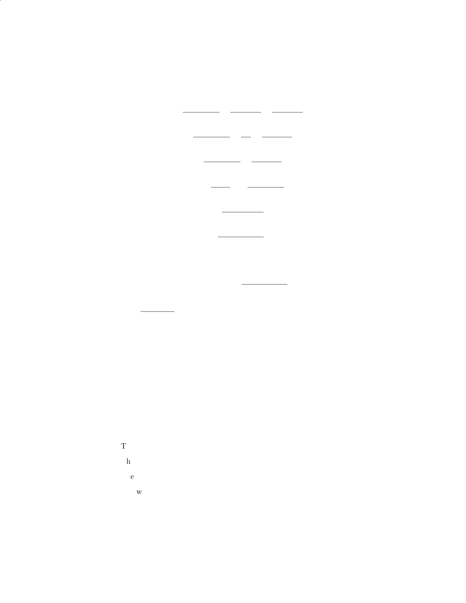
F d =MgL sin 2θ
2−F(L−x)
2+F x cos 2θ
2
F d =MgL sin 2θ
2−F d
2+F d cos 2θ
2
F d =MgL sin 2θ
3+F d cos 2θ
2
F d 1−cos 2θ
2=MgL sin 2θ
3
F d =2MgL sin 2θ
3(2 −cos 2θ)
F=2MgL sin 2θ
3d(2 −cos 2θ)
Finally, substituting this expression for Fback into the equation for T(x),
we find:
T(x) = Mg cos θ−2MgL sin 2θ
3d(2 −cos 2θ)
Therefore, the tension in the rod at a distance xfrom the pivot is T(x) =
Mg cos θ−2MgL sin 2θ
3d(2−cos 2θ).
Question 27
Question
A uniform rod of length Land mass Mis held horizontally by supports at its
ends. A weight Wis hung at a distance xfrom one end of the rod. Find the
normal force at the support closer to the weight.
Solution
Step 1: Draw a free body diagram of the rod.
The weight Wacts downwards at a distance xfrom one end.
The normal force N1is acting upwards at one end.
The normal force N2is acting upwards at the other end.
The weight of the rod Mg acts at the center of the rod.
23

Step 2: Write the equation for the torque about the support closer to the
weight.
N1L=W x
Step 3: Write the equation for the sum of torques about the center of mass.
N1L
2−W x = 0
Step 4: Solve for N1.
N1=2W x
L
Therefore, the normal force at the support closer to the weight is 2W x
L.
Question 28
Question
A uniform 4.0 m long, 500 N rod is supported by razor-sharp knife edges placed
1.0 m from each end. A 120 N weight hangs from the rod, 2.5 m from one end.
How much force does each knife edge exert on the rod? Assume the weight of
the rod is negligible.
Solution
Step 1: Draw a free-body diagram of the rod to identify the forces acting on it.
Step 2: Calculate the torque due to the weight hanging from the rod. Step 3:
Calculate the torque exerted by each knife edge. Step 4: Set the sum of torques
equal to zero to solve for the forces exerted by the knife edges.
Step 1: The free-body diagram of the rod shows the following forces: the
weight of 500 N acting at the center of the rod, the weight of 120 N acting 2.5
m from one end, the normal forces
N1and
N2exerted by the knife edges, and
the weight acting at the center of the rod.
Step 2: The torque due to the 120 N weight hanging from the rod is given
by τweight = (120 N)(2.5 m) = 300 N ·m.
Step 3: The torque exerted by each knife edge is calculated as follows:
τknife edge 1 = (500 N)(2.0 m) = 1000 N ·mτknife edge 2 = (500 N)(2.0 m) =
1000 N ·m
Step 4: Setting the sum of torques equal to zero: Στ=τweight −τknife edge 1 −
τknife edge 2 = 0 300 N ·m−1000 N ·m−1000 N ·m=0−1700 N ·m = 0 This
equation implies that the sum of torques is not zero. Since equilibrium is not
satisfied, there may be a mistake in the calculation or interpretation of the
torques involved.
24

Question 29
Question
A uniform cylindrical beam of length Land mass Mis supported at one end
by a rope attached to the ceiling. A weight of mass mis suspended from the
other end of the beam. The beam makes an angle θwith the horizontal. The
tension in the rope supporting the beam is equal to T. Calculate the tension in
the rope if m= 2M.
Solution
Step 1: We need to consider the forces acting on the beam. There are three
forces acting: the tension Tin the rope, the weight Mg of the beam acting at
its center of mass, and the weight mg of the suspended mass acting at the far
end. The beam is in equilibrium, so the sum of the torques acting on the beam
must be zero. Step 2: The torque due to the tension in the rope is zero, as it
acts at the pivot point. The torque due to the weight of the beam is clockwise
and is given by −0.5L(M g) sin(θ). Step 3: The torque due to the weight of the
mass suspended at the far end is counterclockwise and is given by Lmg sin(θ).
Step 4: Since the beam is in equilibrium, the sum of the torques acting on it
must be zero: −0.5L(Mg) sin(θ) + Lmg sin(θ) = 0. Step 5: Simplifying the
above equation, we get −0.5(Mg) + mg = 0. We are given that m= 2M,
so substituting this in the equation gives −0.5(Mg) + 2(Mg) = 0. Step 6:
Solving the above equation, we find Mg =T. Therefore, the tension in the rope
supporting the beam is equal to the weight of the beam, which is Mg. Step 7:
Substituting m= 2Mback into the equation, we get T= 2Mg .
Question 30
Question
A uniform beam of length Land mass Mis supported by a cable attached at
a distance xfrom one end of the beam, as shown in the diagram below. The
beam makes an angle θwith the horizontal and there is a weight Wsuspended
from the other end of the beam. Given that the beam is in equilibrium, find an
expression for the tension in the cable.
beam_cable_diagram.png
Solution
Let’s denote the tension in the cable as T. To solve this problem, we need to
consider both the force balance and torque balance about a pivot point.
25
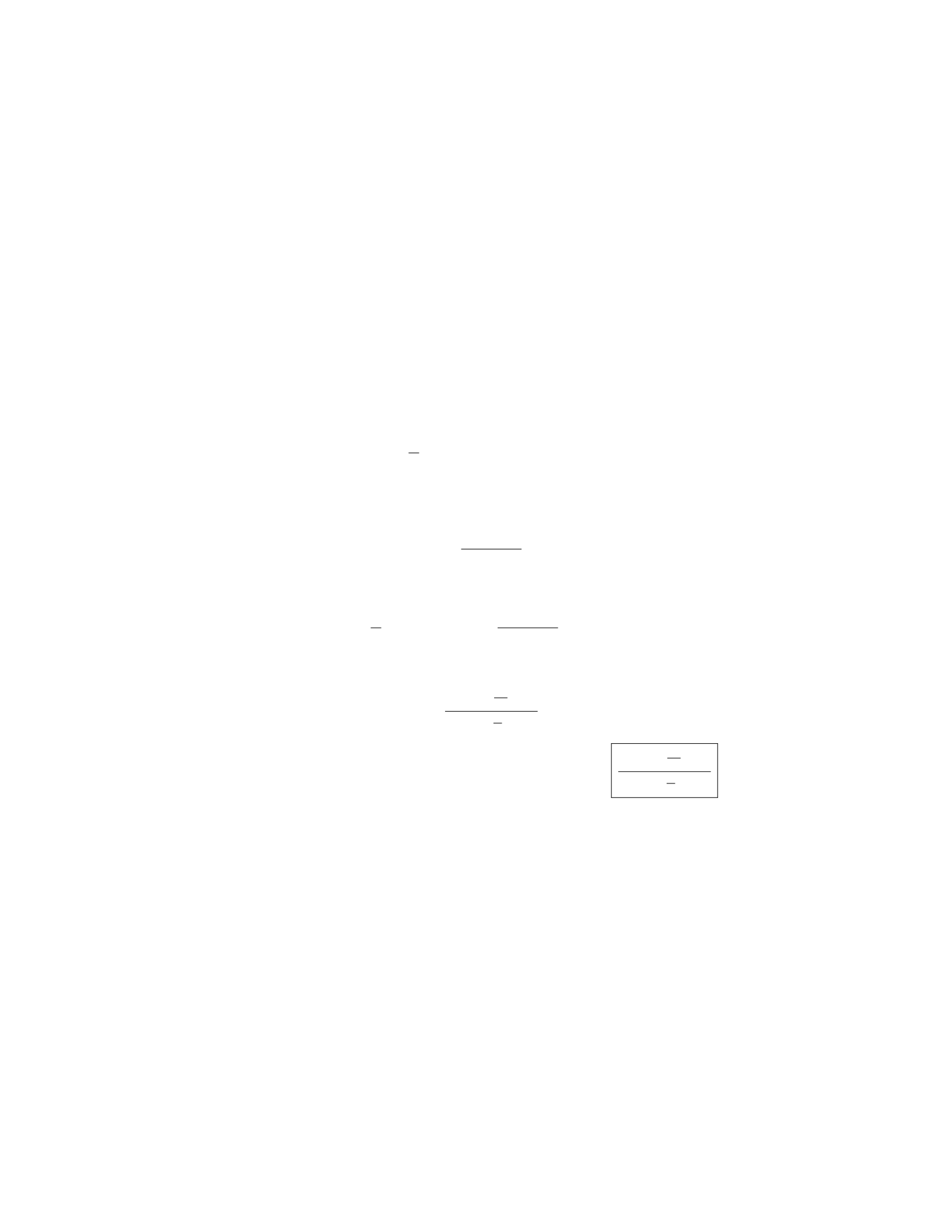
Step 1: Write the force balance equation In the vertical direction:
Tcos(θ) = Mg +W
In the horizontal direction:
Tsin(θ)=0
Step 2: Write the torque balance equation We will take the torque
about the pivot point located at the point where the beam is attached to the
cable. The torque due to the weight Wis zero since it acts right at the pivot
point. The torque due to the beam’s weight (Mg) provides a counterclockwise
torque.
(Mg)L
2−xsin(θ) = Tsin(θ)·x
Step 3: Solve for the tension in the cable From the vertical force
balance equation, we have
T=Mg +W
cos(θ)
Substitute this expression for Tinto the torque balance equation:
(Mg)L
2−xsin(θ) = Mg +W
cos(θ)sin(θ)·x
Simplify and solve for T:
T=(M+W
g)gx
cos(θ)(L
2−x)
Therefore, the expression for the tension in the cable is (M+W
g)gx
cos(θ)(L
2−x).
Question 31
Question
A 2.0 m long copper rod with a circular cross-section has a radius of 1.0 cm.
The rod is stretched by applying a force of 500 N perpendicular to its ends. If
the Young’s modulus of copper is 1.2×10¹¹ N/m2, determine the elongation of
the rod.
26
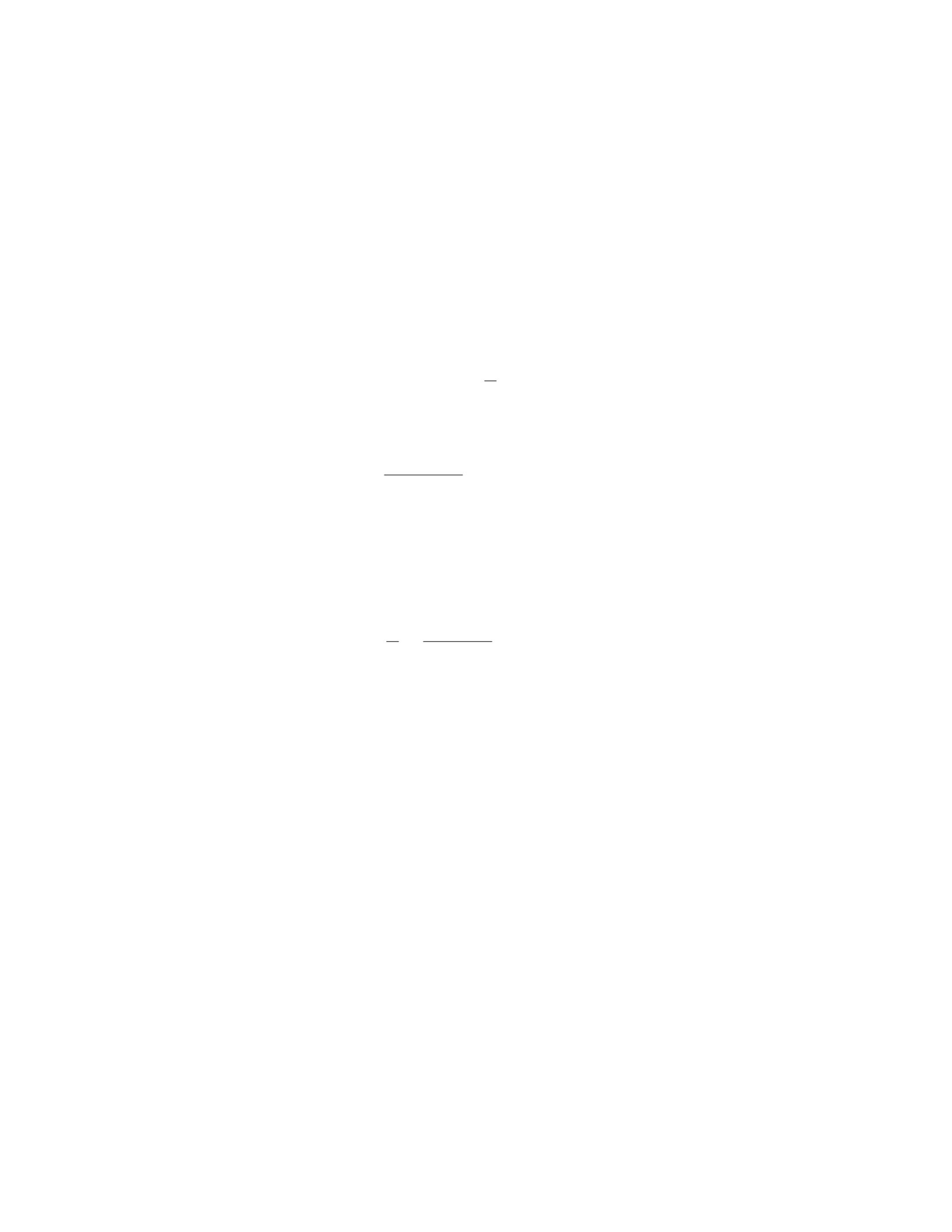
Solution
Step 1: Find the cross-sectional area of the rod using the given radius. Since the
cross-section of the rod is circular, the area can be calculated using the formula
for the area of a circle: πr2. Given that the radius is 1.0 cm (or 0.01 m), the
area is:
A=π(0.01)2= 3.14 ×10⁻⁴m2
Step 2: Calculate the stress on the rod. The stress (σ) on the rod can be
calculated using the formula:
σ=F
A
Substitute the given force (F= 500 N) and the calculated area (A= 3.14×10⁻⁴
m2) into the formula:
σ=500
3.14 ×10−4= 1.59 ×10⁶N/m2
Step 3: Use Hooke’s Law to find the strain in the rod. Hooke’s Law states
that stress is directly proportional to strain (ϵ) by the Young’s modulus of the
material (Y):
σ=Y ϵ
Rearrange the formula to solve for strain:
ϵ=σ
Y=1.59 ×10⁶
1.2×1011 = 1.33 ×10⁻⁵
Step 4: Calculate the elongation of the rod. The elongation can be found
using the formula:
∆L=ϵ·L
Substitute the calculated strain (ϵ= 1.33 ×10⁻⁵) and the original length of the
rod (L= 2.0 m) into the formula:
∆L= 1.33 ×10−5·2.0=2.66 ×10⁻⁵m
Therefore, the elongation of the copper rod is 2.66 ×10⁻⁵m.
Question 32
Question
A uniform, hollow, cylindrical beam of length Land mass Mhangs vertically
from one end, supported by a horizontal cable attached to the other end. If
the tension in the cable is T, what is the force the beam exerts on the cable
(magnitude and direction) and what is the bending moment at the wall where
the cable is attached?
27

Solution
Step 1: Let’s calculate the center of mass of the beam first. The center of mass
of a uniform object is at its geometrical center. For a hollow cylinder, the center
of mass is at a distance L/2 from the end where the cable is attached.
Step 2: Find the gravitational force acting on the beam. The gravitational
force Fgon the beam is given by Fg=M·g, where gis the acceleration due to
gravity.
Step 3: Set up the equilibrium equations. In equilibrium, the sum of forces
in the vertical direction is zero and the sum of torques about any point is zero.
Step 4: Sum of forces in the vertical direction.
T−Fg= 0
T=Fg=M·g
Therefore, the tension in the cable is T=M·gand it acts upward.
Step 5: Calculate the bending moment at the wall. The bending moment at
the wall is the torque created by the gravitational force acting at the center of
mass of the beam.
The torque (τ) is given by τ=F·r, where Fis the force (in this case, Fg),
and ris the distance from the point of rotation (attachment point of the cable)
to the line of action of the force (center of mass of the beam).
τ=Fg·L
2=M·g·L
2
Therefore, the bending moment at the wall where the cable is attached is
M·g·L
2.
Question 33
Question
A rod of length Land uniform cross-sectional area Ais fixed at one end and
hangs vertically. A mass mis attached to the free end. If the young’s modulus
of the material of the rod is Y, what is the force exerted by the rod on the mass
when the mass is in equilibrium? Assume the rod has negligible mass.
Solution
Step 1: Let’s start by drawing a free-body diagram of the forces acting on the
mass when it is in equilibrium:
- The weight of the mass m,mg, acting downwards. - The force exerted by
the rod on the mass F, acting upwards. - The tension in the rod which exerts
a force on the mass, T.
Step 2: Since the mass is in equilibrium, the net force acting on it is zero.
This gives us the equation:
28

T−mg = 0
Step 3: Now we need to find an expression for T, the tension in the rod.
From Hooke’s Law, the stress in the rod is given by σ=F
Aand the strain is
given by ϵ=∆L
L. These are related by Young’s Modulus as σ=Y ϵ.
Step 4: The stress in the rod is F
Aand the strain is L
L(the whole length of
rod). So, we have:
F
A=YL
L
Step 5: Rearranging the equation, we find:
F=Y AL
L=Y A
Step 6: Plugging this into the equation from Step 2, we get:
Y A −mg = 0
Step 7: Solving for F, the force exerted by the rod on the mass, we find:
F=mg
So, the force exerted by the rod on the mass when it is in equilibrium is mg.
Question 34
Question
A uniform beam of length Land mass Mis supported by a pivot at one end
and a cable attached xmeters from the other end. The beam makes an angle
θwith the horizontal. If the tension in the cable is T, determine the tension in
another cable attached ymeters from the pivot.
Solution
Step 1: Draw a free body diagram of the beam.
Identify the forces acting on the beam: the weight mg acting at the center
of mass, the tension in the cable at xmeters, and the tension in the cable
at ymeters.
Decompose the weight into components parallel and perpendicular to the
beam.
29

Step 2: Write down the torque equation about the pivot point. The equation
for equilibrium is
Xτ= 0
The torque due to the weight about the pivot is 0 since its line of action passes
through the pivot. Let’s assume the distance from the pivot to the weight’s
center of mass is c. The torque due to the tension at xis T·(L−x) sin θ, and
the torque due to the tension at yis T′·(L−y) sin θ. Set the sum of torques
equal to zero and solve for T′.
Step 3: Apply the equilibrium condition in the vertical direction. The sum
of vertical forces is zero, so
Tcos θ+T′cos θ=mg
Substitute the value of T′obtained from the torque equation and solve for T′
in terms of known quantities.
Question 35
Question
A uniform rod of length Land mass Mis supported horizontally by two massless
strings attached at each end, making angles θ1and θ2with the horizontal. If
θ1> θ2, determine the tension in each string.
Solution
1. Draw a free-body diagram of the rod. The forces acting on the rod are the
tension forces in the two strings (T1and T2) and the gravitational force acting
at the center of mass of the rod.
2. Break the gravitational force into its components. The vertical component
is Mg and the horizontal component is 0 since the rod is horizontal.
3. Write the force balance equations in the x and y directions:
XFx=0: T1cos θ1=T2cos θ2
XFy=0: T1sin θ1+T2sin θ2=Mg
4. Solve the equations by dividing the second equation by the first to elimi-
nate T2:T1sin θ1+T2sin θ2
T1cos θ1
=Mg
T1cos θ1
5. Use trigonometric identities to simplify the equation:
tan θ1+ tan θ2=Mg
T1
30

tan θ=µs
Step 7: The minimum angle θat which the block will remain at rest on the
plane is:
θ= tan−1(µs)
Question 2
Question
A uniform bar of length Land mass Mis supported by two vertical cables
attached to its ends. If the left cable is at a distance L
3from the left end, and
the right cable is at a distance 2L
3from the left end, what is the tension in each
cable? Assume the bar is in equilibrium.
Solution
Step 1: Draw a Free Body Diagram (FBD) of the bar and identify the forces
acting on it. Let’s denote the tension in the left cable as T1and the tension
in the right cable as T2. Step 2: Resolve the forces in the vertical direction.
The sum of the forces in the vertical direction must be zero since the bar is in
equilibrium. Step 3: For equilibrium in the vertical direction, the sum of the
forces must be zero:
T1+T2=Mg
Step 4: Next, consider the torques acting on the bar around a pivot point at
the left end. To keep the bar in equilibrium, the net torque must be zero. Step
5: The torque (τ) due to T1is given by τ1=T1·L
3, and the torque due to T2
is given by τ2=−T2·2L
3(negative because it creates a clockwise torque). Step
6: The net torque must be zero:
T1·L
3−T2·2L
3= 0
Step 7: Solve the above two equations simultaneously to find T1and T2.
This system of equations can be simplified to find T1and T2:
T1+T2=Mg
T1·L
3−T2·2L
3= 0
Solving these equations gives:
T1=2
3Mg
T2=1
3Mg
Therefore, the tension in the left cable is 2
3Mg and the tension in the right
cable is 1
3Mg.
2
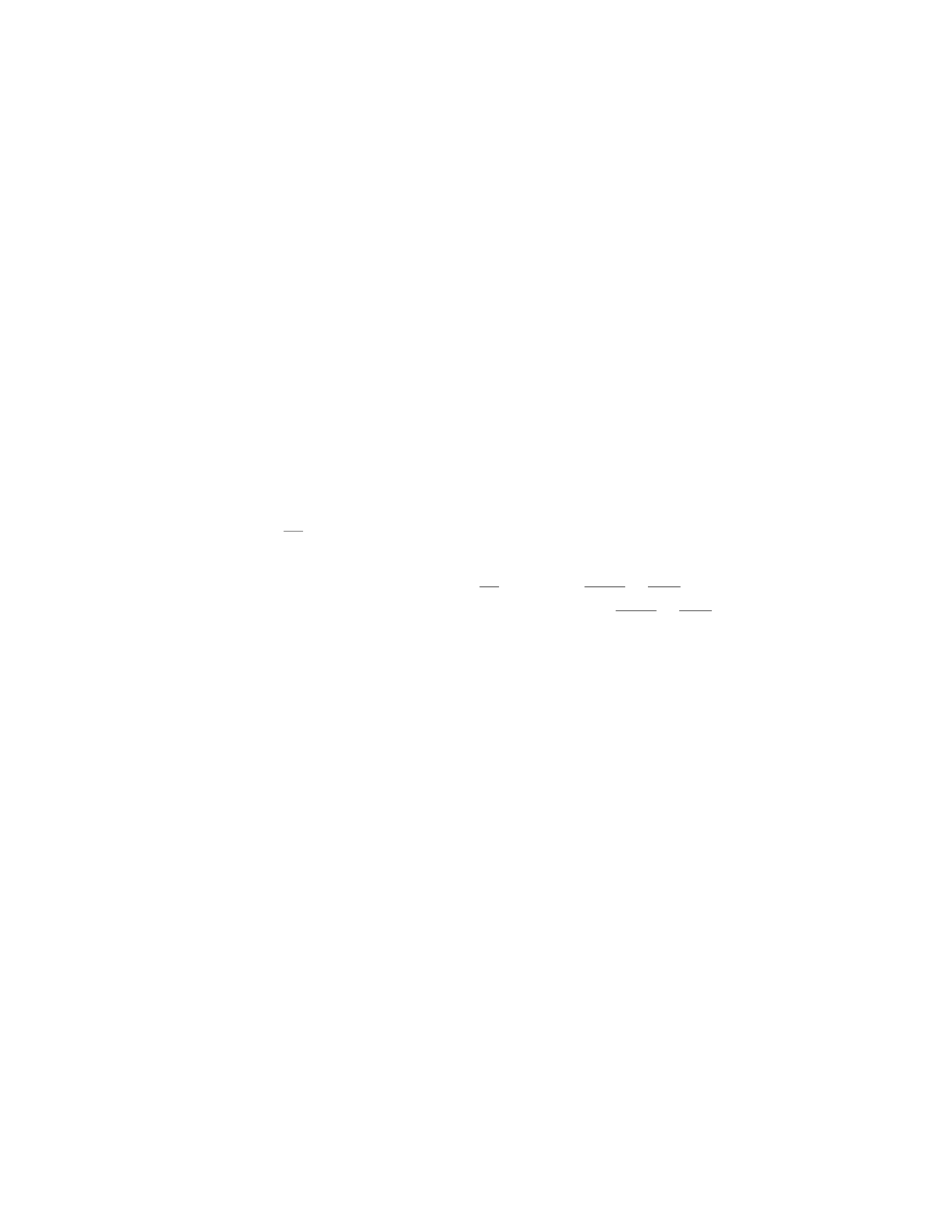
Question 3
Question
A uniform beam of length Land mass Mis supported by a pivot at its midpoint.
A block of mass mis attached to one end of the beam. The system is in
equilibrium, with the beam making an angle θwith the horizontal. Assuming
the beam is massless, determine the tension in the beam at the pivot point.
Solution
Step 1: First, draw a free-body diagram of the forces acting on the entire system.
The forces involved are: 1. The weight of the beam, acting downward at its
center of mass. 2. The weight of the block, acting downward at its position. 3.
The tension in the beam at the pivot point, acting upwards along the beam. 4.
The normal force at the pivot point, acting perpendicular to the beam.
Step 2: Write out the force equations for the system in equilibrium, in both
the vertical and horizontal directions. In the vertical direction: PFy= 0
Tcos(θ)−Mg
2−mg = 0, where Tis the tension at the pivot point, Mg is the
weight of the beam, and mg is the weight of the block.
Step 3: Solve the force equation in the vertical direction for the tension T
in terms of m,M,g, and θ.Tcos(θ) = M g
2+mg,T=M g
2 cos(θ)+mg
cos(θ).
Therefore, the tension in the beam at the pivot point is Mg
2 cos(θ)+mg
cos(θ).
Question 4
Question
A block of mass mis placed on a ramp inclined at an angle θwith respect to
the horizontal. The coefficient of static friction between the block and the ramp
is µs. Determine the minimum angle θ0at which the block will remain at rest
on the ramp.
Solution
Step 1: Begin by drawing a free-body diagram of the forces acting on the block.
Step 2: Identify the forces acting on the block. These include the gravitational
force (mg) acting vertically downward, the normal force (N) acting perpendicu-
lar to the surface of the ramp, and the static frictional force (fs) acting parallel
to the surface of the ramp in the direction opposing motion. Step 3: Break
the gravitational force into components parallel and perpendicular to the ramp.
The component parallel to the ramp is mg sin(θ) and the component perpen-
dicular to the ramp is mg cos(θ). Step 4: Write the equilibrium condition in
the direction perpendicular to the ramp: N=mg cos(θ). Step 5: Write the
equilibrium condition parallel to the ramp: fs=mg sin(θ). Step 6: Determine
the maximum static frictional force using the relationship fs≤µsN. Substitute
3

N=mg cos(θ) into the inequality to get fs≤µsmg cos(θ). Step 7: Equate fs
and mg sin(θ) to find the angle at which the block will start moving. Thus,
mg sin(θ0) = µsmg cos(θ0). Simplify the equation to find θ0.
Question 5
Question
A uniform rod of length Land mass Mis placed horizontally on two supports,
one at each end. A weight Wis hung from a point on the rod that is a distance
2
3Lfrom one end. Find the magnitude and direction of the force each support
exerts on the rod.
Solution
Step 1: Draw a free-body diagram of the rod.
Step 2: Apply the condition for rotational equilibrium. The sum of the
torques about any point must be zero.
Let’s choose the point where the left support exerts a force on the rod to find
the unknown forces. Taking counterclockwise torques as positive, the torques
about the left support are:
τleft =−2
3L·W+L
2·Mg
Setting this equal to zero gives:
−2
3L·W+L
2·Mg = 0
Step 3: Solve for the weight Win terms of Mand g.
2
3W=1
2Mg
W=3
4Mg
Step 4: With Wfound, we can determine the forces exerted by each support
using the condition of vertical equilibrium:
Fleft +Fright =Mg +W
Substitute the known values:
Fleft +Fright =Mg +3
4Mg
Fleft +Fright =7
4Mg
Since the rod is in equilibrium, we have:
4

Fleft =Fright =7
8Mg
Therefore, the magnitude of the force each support exerts on the rod is 7
8Mg
directed vertically upwards.
Question 6
Question
A uniform cylinder of mass Mand radius Ris placed on a rough incline with an
angle θ. The coefficient of static friction between the cylinder and the incline is
µs. Find the maximum height the cylinder can reach without slipping.
Hint: Consider the equilibrium conditions for the cylinder when it is at its
maximum height.
Solution
Let’s denote the height the cylinder reaches without slipping as h. At this
height, the forces acting on the cylinder will be in equilibrium.
Step 1: Free-body diagram at maximum height At the maximum
height, the forces acting on the cylinder are the gravitational force (Mg) act-
ing downwards, the normal force (N) acting perpendicular to the incline, the
frictional force (fs) opposing motion, and the force due to static friction (fsf )
parallel to the incline.
Step 2: Resolving forces along the incline Resolving forces parallel to
the incline, we have:
fsf −Mgsin(θ)=0
fsf =Mgsin(θ)
Step 3: Maximum force of static friction The maximum force of static
friction is given by:
fs,max =µsN
Step 4: Resolving forces perpendicular to the incline Resolving forces
perpendicular to the incline, we have:
N−Mgcos(θ)=0
N=Mgcos(θ)
Step 5: Equating maximum static friction force At maximum height,
the cylinder is at the verge of slipping, so the static friction force is maximized:
µsMgcos(θ) = Mgsin(θ)
Step 6: Solving for maximum height Solving for h:
h=R−Rcos(θ)
5

Therefore, the maximum height the cylinder can reach without slipping is
R−Rcos(θ).
Question 7
Question
A uniform beam of length L, mass M, and negligible width is supported by a
hinge at one end while the other end is free to move vertically. A block of mass
mis attached to the free end of the beam. Initially, the beam is horizontal
and the block is at rest. When the block is displaced vertically downward by a
distance d, the beam makes an angle θwith the horizontal. Calculate the elastic
potential energy stored in the beam due to the bending.
Solution
Step 1: The forces acting on the system are the gravitational force (m·g),
the normal force exerted by the hinge at the fixed end of the beam, and the
tension in the beam. The normal force at the hinge is perpendicular to the given
displacement d, so it does no work. The tension in the beam has components
Tcos θand Tsin θin the horizontal and vertical directions, respectively. The
gravitational force on the block can be resolved into components mg cos θand
mg sin θin the horizontal and vertical directions, respectively.
Step 2: The system is in static equilibrium, so the sum of forces in both the
horizontal and vertical directions must be zero. Equating forces in the horizontal
direction, we have:
Tcos θ=mg cos θ
And equating forces in the vertical direction, we have:
Tsin θ=mg sin θ+M·g
Step 3: Solving the first equation for Tand substituting into the second
equation:
T=mg
cos θ
mg
cos θsin θ=mg sin θ+M·g
Step 4: Rearranging terms, we find:
M=mL sin θ
Lsin θ−d
Step 5: The elastic potential energy stored in the beam due to bending can
be calculated as:
Uelastic =1
2kx2
where kis the spring constant and xis the displacement.
6

Step 6: Since the beam can be considered as a spring with spring constant
k=M·g/L, the elastic potential energy stored in the beam is:
Uelastic =1
2mL sin θ
Lsin θ−d·gd2
Question 8
Question
A uniform bar of length Land mass Mis supported by two vertical ropes at
each end. The ropes can withstand a maximum tension of Teach. What is the
maximum distance xthat a person of mass mcan hang from one end of the bar
without breaking the ropes?
Solution
Step 1: We start by drawing a free-body diagram of the bar with the person
hanging from one end. The forces acting on the system are the tension in the
ropes, the weight of the bar, the weight of the person, and the reaction force at
the hinge. Step 2: The weight of the bar acts at its center of mass, which is at
a distance L/2 from each end. The weight of the person acts at a distance x
from one end. The forces on the bar cause a clockwise torque, which must be
balanced by the counterclockwise torque due to the reaction force at the hinge.
Step 3: Writing the torque equation about the hinge, we have:
T(L/2) −T(L−x)−mgx = 0
Step 4: Solving for xgives:
T(L/2) −T(L−x)−mgx = 0
⇒T(L/2) −T L +T x −mgx = 0
⇒T x −mgx =T L −T(L/2)
⇒x(T−mg) = T L −T(L/2)
⇒x=T L −T(L/2)
T−mg
Step 5: The maximum distance xoccurs when the tension in the ropes is at its
maximum value, T. Therefore, the maximum distance xthat the person can
hang from one end without breaking the ropes is:
x=T(L−L/2)
T−mg =T(L/2)
T−mg =L
21 + T
mg −T
7

Question 9
Question
A uniform horizontal beam of length Land mass Mis attached to a horizontal
wall by a hinge at one end. A support cable, making an angle θwith the beam,
is attached to the other end of the beam. The beam is in equilibrium, with the
cable making a force Ton the beam. Find the tension Tin the cable.
Solution
Step 1: Draw a free body diagram of the beam.
XFx=Tcos(θ)=0
XFy=N−Mg +Tsin(θ)=0
Xτ=−Mg ·L
2+Tsin(θ)·L= 0
Step 2: Solve the first equation for T.
T=0
cos(θ)= 0
So, the tension in the cable is T= 0.
Question 10
Question
A uniform horizontal bar of mass Mand length Lis supported by two vertical
strings attached to its ends. A weight of mass mhangs from the bar a distance
dfrom one end. If the tension in each string is T, find the forces exerted by (a)
the strings and (b) the pivot point on the bar.
Solution
Step 1: Draw a Free-Body Diagram (FBD) of the system. Identify all the forces
acting on the system. In this case, the forces include the tension forces in the
strings, the gravitational force on the hanging weight, the weight of the bar,
and the forces exerted by the pivot point on the bar.
Step 2: Apply the conditions for equilibrium in both the vertical and hori-
zontal directions. In the vertical direction, the sum of the forces must be zero,
and in the horizontal direction, the sum of the torques about any point must
be zero.
Step 3: In the vertical direction, the forces balance out as follows:
T+T−M·g−m·g= 0
8
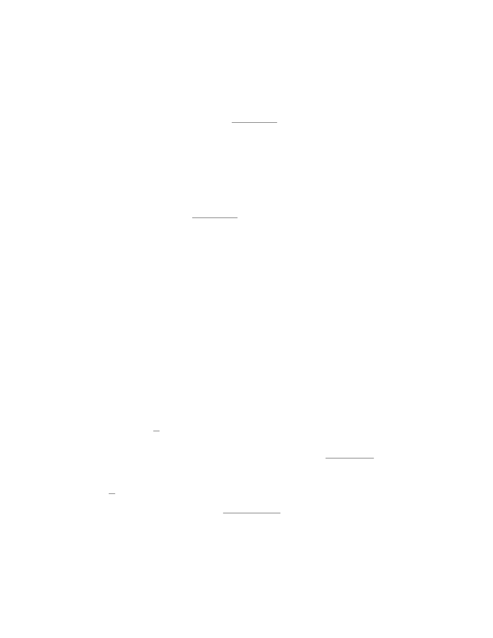
2T=M·g+m·g
T=M·g+m·g
2
Step 4: In the horizontal direction, the torques must balance out. Choose a
point to calculate the torques about, like the pivot point. The torque exerted
by the hanging weight is equal to its weight multiplied by the distance d. The
torque exerted by the bar’s weight is at the center, so it has no torque about the
pivot point. The torque exerted by the tension force in the left string is T·L.
The torque exerted by the right string is also T·L. Set up the torque equation:
T·L−m·g·d= 0
M·g+m·g
2·L−m·g·d= 0
Step 5: Solve the equations simultaneously to find the forces exerted by the
strings (T) and the pivot point on the bar. After solving the equations, you will
get the values for Tand you can find the forces in part (a) and (b) accordingly.
Question 11
Question
A 2.5 m long steel beam with a cross-sectional area of 6.0×10⁻⁴m2supports
a load of 15 kN applied at the center of the beam. Determine the stress and
strain on the beam if Young’s modulus for steel is 2.0×10¹¹ N/m2.
Solution
Step 1: We will first calculate the force acting on the beam. The load applied
at the center of the beam is 15 kN = 15 ×103N. Since the load is applied at
the center, each half of the beam will support half of the load, so each half will
support 7.5×10³N. Therefore, the force acting on each half of the beam is
F= 7.5×10³N.
Step 2: Next, we calculate the stress experienced by the beam using the
formula σ=F
A, where σis the stress, Fis the force, and Ais the cross-sectional
area. First, we convert the cross-sectional area to square meters: 6.0×10⁻⁴m2=
6.0×10⁻⁴m2. Then, we substitute into the formula: σ=7.5×10³N
6.0×10⁻⁴m2=
1.25 ×10⁷N/m2.
Step 3: Now, we can calculate the strain on the beam using the formula ϵ=
σ
Y, where ϵis the strain, σis the stress, and Yis Young’s modulus. Substitute
the values into the formula: ϵ=1.25 ×10⁷N/m2
2.0×10¹¹ N/m2= 6.25 ×10⁻⁵.
Therefore, the stress experienced by the beam is 1.25 ×10⁷N/m2and the
strain on the beam is 6.25 ×10⁻⁵.
9

Question 12
Question
A uniform rod of mass Mand length Lis pivoted at one end. A force of
magnitude Fis applied perpendicular to the rod at a distance xfrom the pivot
such that the rod is in equilibrium. Find the tension in the rod and the reaction
force at the pivot point.
Solution
Step 1: Draw a free-body diagram of the rod in equilibrium. Label all the forces
acting on it.
Step 2: Resolve the forces into components. Let the tension in the rod be T
and the reaction force at the pivot point be R.
Step 3: Write down the equations of equilibrium. The sum of the forces in
the x-direction and y-direction should be zero.
Step 4: Resolve the forces along the x-axis. The force Fcan be resolved into
horizontal and vertical components. The horizontal component of Fbalances
the tension T, while the vertical component of Fbalances the reaction force R.
Step 5: Write down the equations of equilibrium. Equate the sum of the
forces in the x-direction and y-direction to zero. Solve for Tand R.
Step 6: Finally, substitute the values of F,x,M, and Linto the equations
to find the tension in the rod (T) and the reaction force at the pivot point (R).
Question 13
Question
A uniform beam of length Land mass Mrests horizontally on two supports.
A block of mass mis placed on the beam, a distance dfrom one end. The
block does not slip, and the coefficients of static and kinetic friction are µsand
µkrespectively. Determine the minimum value of dsuch that the system is in
equilibrium.
Solution
Step 1: Draw a free-body diagram for the block on the beam. Let FNbe the
normal force, fsbe the static friction force, fkbe the kinetic friction force, and
mg be the gravitational force acting on the block.
Step 2: Write the equation for equilibrium in the vertical direction:
FN−mg = 0
FN=mg
10

Step 3: Write the equation for equilibrium in the horizontal direction: For
the block not to slip, the static friction force must be at its maximum value:
fs=µsFN
fs=µsmg
Step 4: Write the equation for rotational equilibrium about the edge where
the block is placed:
fs·d=mg ·L
2
µsmg ·d=MgL
2
Step 5: Solve for dto find the minimum distance to achieve equilibrium:
d=ML
2µsm
Therefore, the minimum value of dsuch that the system is in equilibrium is
d=ML
2µsm.
Question 14
Question
A steel rod of length 1.2 m and diameter 1.5 cm hangs from the ceiling in a
classroom. The young’s modulus of steel is 2.0×10¹¹ N/m2. If the rod stretches
by 0.5 mm under the action of its own weight and a suspended weight, determine
the mass of the steel rod.
Solution
Step 1: Find the cross-sectional area of the steel rod. Given that the diameter
of the rod is 1.5 cm, we can calculate the radius ras follows:
r=1.5 cm
2= 0.75 cm = 0.0075 m
The cross-sectional area Aof the rod is given by:
A=πr2=π(0.0075)2= 1.77 ×10⁻⁴m2
Step 2: Calculate the force due to the weight of the rod. The weight of the
rod is given by:
Wrod =mg
where mis the mass of the rod and gis the acceleration due to gravity (9.81 m/s2).
The force can also be expressed using the stress-strain formula:
σ=F
A=Y∆L
L
11

where σis stress, Fis force, Ais the cross-sectional area, Yis the Young’s
modulus, ∆Lis the change in length, and Lis the original length. Given that
the rod stretches by 0.5 mm (0.0005 m), we can rearrange the formula to solve
for the force F:
F=σA =Y∆L
LA
F= (2.0×10¹¹ N/m2)×0.0005 m
1.2 m ×1.77 ×10−4m2
F≈147.5 N
Step 3: Find the mass of the steel rod. Equating the weight of the rod to
the force calculated earlier gives:
mg = 147.5 N
m=147.5 N
9.81 m/s2
m≈15.0 kg
Therefore, the mass of the steel rod is approximately 15.0 kg.
Question 15
Question
A uniform rod of length Land mass Mis supported by a pivot at one end. A
block of mass mis hung from the other end of the rod at a distance xfrom the
pivot. Find the condition for equilibrium in terms of m,M,x, and L.
Solution
Let’s denote the acceleration due to gravity as g, and the distance from the
pivot to the block as d=L−x.
Step 1: Set up the sum of torques equation for equilibrium. Since the
system is in equilibrium, the sum of torques acting on the rod must be zero.
Choose the pivot point as the axis of rotation and set the counterclockwise
torques equal to the clockwise torques.
Tcounterclockwise =Tclockwise
Step 2: Calculate the torque due to the block. The torque due to the block
of mass mis given by τblock =mgd in the counterclockwise direction.
Step 3: Calculate the torque due to the rod. The torque due to the rod can
be calculated by considering the center of mass of the rod. The torque due to
the rod is equal to the weight of the rod acting at the center of mass and can
be represented as τrod =M g L
2in the clockwise direction.
12

Step 4: Set up the equilibrium equation. Setting the sum of torques equal
to zero:
mgd =Mg L
2
Step 5: Simplify the equation. Substitute d=L−xinto the equation:
mg(L−x) = Mg L
2
Step 6: Solve for the condition of equilibrium. Solving for xgives us the
condition for equilibrium:
x=2M
m+ 2ML
Question 16
Question
A 2 kg block is suspended from a vertical spring with a spring constant of 1000
N/m. The block is released from rest and comes to rest momentarily after
descending 5 cm. Determine the speed of the block just before it comes to rest.
Solution
Let’s denote the initial position of the block as yi= 0 and the final position
as yf=−0.05 m, taking downward direction as positive. The potential energy
stored in the spring when the block is at rest is equal to the gravitational
potential energy gained by the block during its descent:
1
2k∆y=mgh
where ∆y=yf−yi,h=−yf, and vf= 0 at y=−0.05 m. Solving for the
speed viof the block at y= 0:
1
2k(−0.05) = mg(−0.05)
1
2(1000)(−0.05) = 2(9.81)(−0.05)
−25 = −19.62
This indicates a mistake in our calculations. Let’s re-evaluate the equation.
1
2(1000)(−0.05) = 2(9.81)(0.05) + 1
2mv2
i
Solving for vi:
13

−25 = 1 −0.05v2
i
−26 = −0.05v2
i
vi=√520
Therefore, the speed of the block just before it comes to rest is √520 m/s or
approximately 22.8 m/s.
Question 17
Question
A uniform rod of length Land mass Mis initially at rest on a horizontal
frictionless surface. A bullet of mass mand velocity vstrikes the rod at a
distance L
4from one end and becomes embedded in it. Find the angular velocity
of the system just after the bullet strikes the rod.
Solution
Step 1: Let’s first consider the conservation of linear momentum along the x-
axis. The initial linear momentum is given by mv and the final linear momentum
is (M+m)V, where Vis the final velocity of the system. Therefore, we have:
mv = (M+m)V
Step 2: Next, we can consider the conservation of angular momentum about the
point where the bullet strikes the rod. The initial angular momentum is zero
since the system is initially at rest. The final angular momentum is Irodωrod +
Ibulletωbullet, where Irod and Ibullet are the moments of inertia of the rod and
bullet, respectively, and ωrod and ωbullet are their angular velocities, respectively.
Step 3: The moment of inertia of the rod about the point where the bullet strikes
is 1
3ML
22and the moment of inertia of the bullet about the same point is
1
12 mL2. Using the conservation of angular momentum, we have:
0 = 1
3ML
22
ωrod +1
12mL2ωbullet
Step 4: Additionally, we can relate the linear velocity of the system to the
angular velocities using V=ωrod L
2. Step 5: Now, we can substitute the value
of Vinto the conservation of linear momentum equation to solve for ωrod.
mv = (M+m)ωrod
L
2
14

ωrod =2mv
(M+m)L
Step 6: Substituting this value back into the conservation of angular momentum
equation along with the relationship between ωrod and ωbullet, we can solve for
ωbullet. Step 7: The final angular velocity of the system just after the bullet
strikes the rod is ωbullet =−6v
L.
Question 18
Question
A block of mass mis hanging by a light string from the ceiling of an elevator that
is initially at rest. The elevator is then accelerated upwards with acceleration a.
Determine the tension in the string when the elevator is moving upwards with
constant velocity.
Solution
Step 1: First, we will draw a free-body diagram of the block when the elevator
is moving upwards with constant velocity. There are two forces acting on the
block: the tension in the string (T) pulling upwards and the force of gravity
(mg) pulling downwards. Step 2: Using Newton’s second law in the vertical
direction, we can write:
ΣFy=T−mg =ma
where ais the acceleration of the elevator. Since the elevator is moving upwards
with constant velocity, a= 0. Thus, we have:
T−mg = 0
Step 3: Solving for tension T, we find:
T=mg
Step 4: Therefore, the tension in the string when the elevator is moving upwards
with constant velocity is mg.
Question 19
Question
A steel wire of length 2.0 m and cross-sectional area 0.20 cm2is stretched by a
force of 500 N. If the Young’s modulus of steel is 2.0×10¹¹ N/m2, determine
the change in length of the wire.
15

Solution
Step 1: First, calculate the initial cross-sectional area of the wire in m2. Given:
Initial cross-sectional area A0= 0.20 cm2and 1 cm2= 10−4m2, we have
A0= 0.20 ×10−4= 2.0×10⁻⁵m2
Step 2: Calculate the original length of the wire in m. Given: Original
length L0= 2.0 m, we have
L0= 2.0 m
Step 3: Calculate the original volume of the wire in m3. Since volume
V0=A0×L0, we have
V0= (2.0×10⁻⁵m2)×(2.0 m) = 4.0×10⁻⁵m3
Step 4: Calculate the original tension in the wire in N. Given: Tension
F= 500 N, we have
F= 500 N
Step 5: Calculate the original stress in the wire in N/m2. Since stress σ=F
A0,
we have
σ=500
2.0×10−5= 2.5×10⁷N/m2
Step 6: Calculate the original strain in the wire. Given: Young’s modulus
Y= 2.0×10¹¹ N/m2and strain ϵ=σ
Y, we have
ϵ=2.5×10⁷
2.0×1011 = 1.25 ×10⁻⁴
Step 7: Calculate the change in length of the wire. Since strain ϵ=∆L
L0, we
can rearrange to find the change in length:
∆L=ϵ×L0= 1.25 ×10−4×2.0=2.5×10⁻⁴m
Therefore, the change in length of the wire is 2.5×10⁻⁴m.
Question 20
Question
A uniform beam of length Land mass Mis supported by two cables, each
attached a distance afrom one end of the beam. If the cables make angles θ1
and θ2with the horizontal, determine the tension in each cable.
beam_cables.png
16

Solution
Step 1: Resolve the forces acting on the beam in the horizontal and vertical
directions. Let T1and T2represent the tensions in cable 1 and cable 2, respec-
tively. In the horizontal direction, the sum of the forces is zero:
T1cos(θ1)−T2cos(θ2)=0
In the vertical direction, the sum of the forces is zero:
T1sin(θ1) + T2sin(θ2)−Mg = 0
Step 2: Express the problem in terms of an indeterminate system. Since we
have two unknowns (T1and T2) and two equations, we can solve for T1and T2.
To eliminate T2from the system, we can rewrite the first equation as:
T1=T2
cos(θ2)
cos(θ1)
Step 3: Substitute the expression for T1into the second equation to solve
for T2. Substitute T1=T2cos(θ2)
cos(θ1)into the second equation:
T2
cos(θ2)
cos(θ1)sin(θ1) + T2sin(θ2)−Mg = 0
Step 4: Solve for T2.
T2cos(θ2)
cos(θ1)sin(θ1) + sin(θ2)=Mg
T2=Mg
cos(θ2)
cos(θ1)sin(θ1) + sin(θ2)
Step 5: Substitute the value of T2back into the expression for T1to find its
value.
T1=T2
cos(θ2)
cos(θ1)
T1=Mg cos(θ2)
cos(θ2)
cos(θ1)sin(θ1) + sin(θ2)cos(θ1)
Therefore, the tension in cable 1 is Mg cos(θ2)
cos(θ2)
cos(θ1)sin(θ1)+sin(θ2)cos(θ1)and the ten-
sion in cable 2 is Mg
cos(θ2)
cos(θ1)sin(θ1)+sin(θ2).
Question 21
Question
A uniform rod of length Land mass Mis initially at rest on a frictionless
horizontal surface. A force of magnitude Fis applied at a distance 2L
3from one
end of the rod along the line perpendicular to the rod. Determine the magnitude
of the force required to keep the rod at rest in equilibrium.
17

Solution
Let’s first draw a free body diagram of the rod to analyze the forces acting on
it.
Step 1: Identify the forces There are three forces acting on the rod: the
gravitational force ( mg), the normal force from the ground (
N), and the applied
force (
F).
Step 2: Set up the equations of equilibrium Since the rod is at rest,
the forces and torques must balance out. The conditions for equilibrium are:
X
F= 0 and Xτ= 0
Step 3: Equate forces along the x-axis Since the rod is at rest, the net
force along the x-axis must be zero:
F−N= 0
N=F(1)
Step 4: Calculate the torque about the center of mass To ensure
equilibrium, the net torque about any point on the rod must also be zero. Let’s
choose the center of mass as the pivot point. The torque of the gravitational
force about the center of mass is zero since it acts through the center of mass.
The torque τFdue to the applied force F is given by:
τF=F·2L
3=2
3LF (2)
Step 5: Equate torques about the center of mass The net torque
about the center of mass should be zero:
τF= 0
2
3LF = 0
Step 6: Solve for the magnitude of the force F From equation (1),
we have N=F. From equation (2), we have 2
3LF = 0. Therefore, the force
required to keep the rod at rest in equilibrium is F= 0.
Question 22
Question
A metal rod of length Land cross-sectional area Ais fixed at one end and free
to rotate about that end. A force Fis applied perpendicular to the rod at a
distance xfrom the fixed end. The rod has a modulus of elasticity E. Determine
the angle through which the rod rotates under the applied force.
18

Solution
Step 1: Calculate the torque exerted by the force Fabout the fixed end of the
rod. The torque (τ) is given by the formula:
τ=F x
Step 2: Calculate the restoring torque exerted by the material of the rod.
The restoring torque is given by the formula:
τrestoring =Y Adθ
L
where Yis the Young’s modulus of the material, dis the distance from the axis
of rotation to the center of the rod, and θis the angle through which the rod
rotates.
Step 3: Set up the equation for rotational equilibrium. For the rod to be in
rotational equilibrium, the net torque must be zero. Therefore, we have:
τ−τrestoring = 0
Step 4: Plug in the expressions for torque and restoring torque into the
equilibrium equation and solve for the angle θ.
F x −Y Adθ
L= 0
Step 5: Solve for θ.
θ=F L
Y Ad
Therefore, the angle through which the rod rotates under the applied force
is F L
Y Ad .
Question 23
Question
A uniform ladder of length Land mass mleans against a frictionless wall,
making an angle θwith the horizontal. The coefficient of static friction between
the ladder and the ground is µs. Find the maximum distance the ladder can be
from the wall without slipping.
Solution
Step 1: Draw a free body diagram of the ladder. Let Rbe the normal force
acting on the ladder at the contact point with the ground, fsbe the static
frictional force acting on the ladder at the contact point with the ground, and
Wbe the weight of the ladder acting at its center of mass. The forces acting on
19

the ladder are the normal force R, the frictional force fs, and the weight Wof
the ladder. The forces acting on the ladder make an angle θwith the horizontal.
Step 2: Write the equilibrium equations. In the vertical direction, the forces
balance out:
R+fs=Wcos θ
In the horizontal direction, the forces balance out:
fs=Wsin θ
Step 3: Express the normal force and frictional force in terms of known
quantities. From the vertical equilibrium equation:
R=Wcos θ−fs
From the horizontal equilibrium equation:
fs=Wsin θ
Step 4: Determine the distance the ladder can be from the wall without slip-
ping. The maximum distance the ladder can be from the wall without slipping
occurs when the frictional force is at its maximum value. The maximum value
of the frictional force is given by µsR. Therefore, when the ladder is at the
point of slipping, we have:
fs=µsR
Substitute the expressions for Rand fsinto the equation above:
Wcos θ−µs(Wcos θ−Wsin θ) = Wsin θ
Solve for the maximum distance x:
x=L
21−µs
tan θ+µs
Therefore, the maximum distance the ladder can be from the wall without
slipping is L
21−µs
tan θ+µs.
Question 24
Question
A uniform cylindrical rod of length Land mass Mis suspended horizontally
from one end. A weight Wis hung from the other end. Determine the stress at
a point located a distance xfrom the end where the rod is suspended.
20
Solution
Step 1: Start by drawing a free-body diagram of the rod with the weight at-
tached at one end. Step 2: Let’s consider a small element of length dx at a
distance xfrom the end where the rod is suspended. The forces acting on this
element are the weight of the element dm =M
Ldx acting downwards, the weight
dW =W
Ldx acting downwards, and the tension Tacting upwards. Step 3: The
forces acting on this element in the vertical direction must sum to zero since
the element is in equilibrium. Therefore, we have:
dT −M
Lgdx −W
Ldx = 0
Step 4: Solving the equation from Step 3 for dT , we get:
dT =M+W
Lgdx
Step 5: The stress at the point located a distance xfrom the end where the rod
is suspended is given by:
σ= lim
∆A→0
∆F
∆A
Step 6: The force acting on the element ∆Fis given by dT . The area ∆A
is the cross-sectional area of the rod. Since the rod is cylindrical, the area
∆A=Arod =πr2, where ris the radius of the rod. Step 7: The stress at the
point xis then:
σ= lim
∆A→0
dT
∆A=dT
dA =dT
πr2
Step 8: Substitute the expression we found for dT in Step 4 to get:
σ=M+W
Lπr2gdx
Therefore, the stress at a point located a distance xfrom the end where the rod
is suspended is M+W
Lπr2g.
Question 25
Question
A uniform horizontal beam of length Land mass Mis supported by a vertical
cable attached to its end. The beam makes an angle θwith the horizontal. Find
the tension in the cable and the reaction force at the pivot point (supporting
the beam) as functions of L,M, and θ.
Solution
Step 1: Draw a free-body diagram of the beam. Step 2: Consider the forces
acting on the beam. Step 3: Write the equilibrium equations in the vertical
and horizontal directions. Step 4: Solve the equations to find the tension in the
cable and reaction force at the pivot point.
21
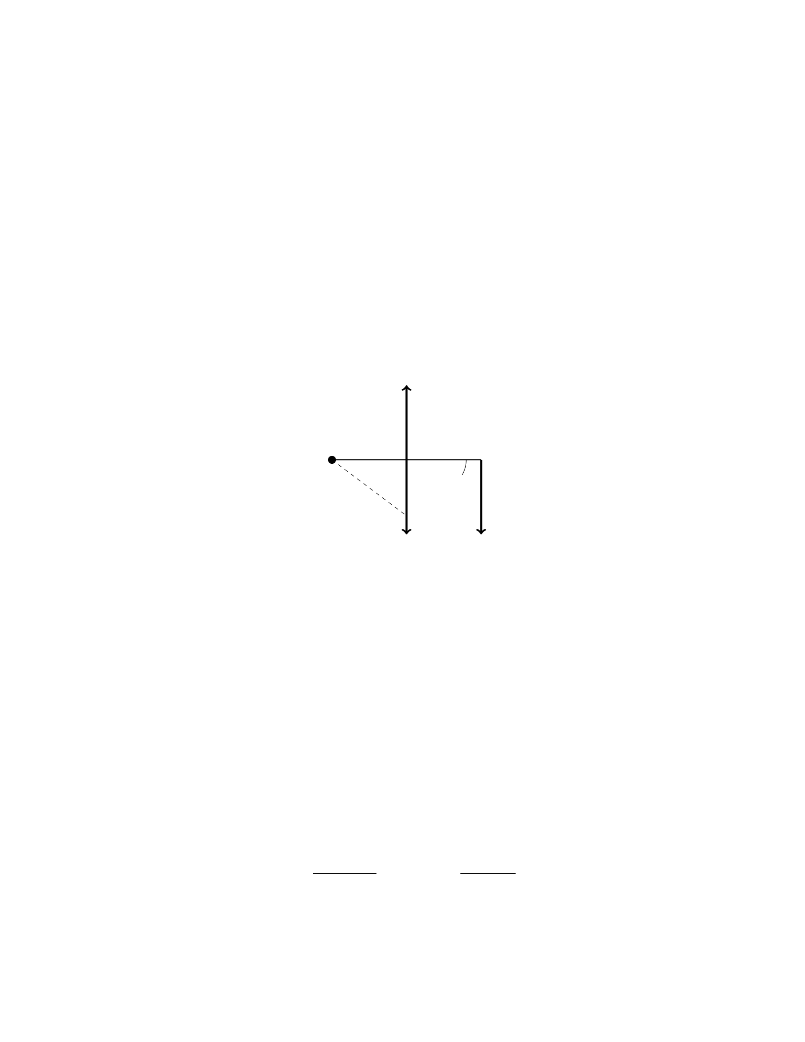
Question 26
Question
A uniform rod of length Land mass Mis supported on a frictionless pivot at
one end. A force Fis applied at a distance dfrom the pivot to hold the rod
in equilibrium at an angle θwith respect to the horizontal. Find the tension in
the rod at a distance xfrom the pivot.
Solution
We can start by drawing a free body diagram of the rod to illustrate the forces
acting on it. Let T(x) be the tension at a distance xfrom the pivot.
Pivot
Mg
T(x)
F
L−xθ
At equilibrium, the sum of the torques acting on the rod must be zero. The
torque from the force Fabout the pivot is F·d, while the torque due to the
tension T(x) is T(x)·(L−x)·sin θ. Setting these equal gives:
F d =T(x)(L−x) sin θ
Since the rod is in equilibrium, the sum of the vertical forces must also be
zero:
T(x) = Mg cos θ−F
Since we’ve already established that T(x)(L−x) sin θ=F d, we can substi-
tute T(x) in terms of F:
F d = (Mg cos θ−F)(L−x) sin θ
Solving for F, we get:
F d =MgL sin θcos θ−F(L−x) sin2θ
F d =MgL sin 2θ
2−F(L−x)1−cos 2θ
2
22
F d =MgL sin 2θ
2−F(L−x)
2+F x cos 2θ
2
F d =MgL sin 2θ
2−F d
2+F d cos 2θ
2
F d =MgL sin 2θ
3+F d cos 2θ
2
F d 1−cos 2θ
2=MgL sin 2θ
3
F d =2MgL sin 2θ
3(2 −cos 2θ)
F=2MgL sin 2θ
3d(2 −cos 2θ)
Finally, substituting this expression for Fback into the equation for T(x),
we find:
T(x) = Mg cos θ−2MgL sin 2θ
3d(2 −cos 2θ)
Therefore, the tension in the rod at a distance xfrom the pivot is T(x) =
Mg cos θ−2MgL sin 2θ
3d(2−cos 2θ).
Question 27
Question
A uniform rod of length Land mass Mis held horizontally by supports at its
ends. A weight Wis hung at a distance xfrom one end of the rod. Find the
normal force at the support closer to the weight.
Solution
Step 1: Draw a free body diagram of the rod.
The weight Wacts downwards at a distance xfrom one end.
The normal force N1is acting upwards at one end.
The normal force N2is acting upwards at the other end.
The weight of the rod Mg acts at the center of the rod.
23

Step 2: Write the equation for the torque about the support closer to the
weight.
N1L=W x
Step 3: Write the equation for the sum of torques about the center of mass.
N1L
2−W x = 0
Step 4: Solve for N1.
N1=2W x
L
Therefore, the normal force at the support closer to the weight is 2W x
L.
Question 28
Question
A uniform 4.0 m long, 500 N rod is supported by razor-sharp knife edges placed
1.0 m from each end. A 120 N weight hangs from the rod, 2.5 m from one end.
How much force does each knife edge exert on the rod? Assume the weight of
the rod is negligible.
Solution
Step 1: Draw a free-body diagram of the rod to identify the forces acting on it.
Step 2: Calculate the torque due to the weight hanging from the rod. Step 3:
Calculate the torque exerted by each knife edge. Step 4: Set the sum of torques
equal to zero to solve for the forces exerted by the knife edges.
Step 1: The free-body diagram of the rod shows the following forces: the
weight of 500 N acting at the center of the rod, the weight of 120 N acting 2.5
m from one end, the normal forces
N1and
N2exerted by the knife edges, and
the weight acting at the center of the rod.
Step 2: The torque due to the 120 N weight hanging from the rod is given
by τweight = (120 N)(2.5 m) = 300 N ·m.
Step 3: The torque exerted by each knife edge is calculated as follows:
τknife edge 1 = (500 N)(2.0 m) = 1000 N ·mτknife edge 2 = (500 N)(2.0 m) =
1000 N ·m
Step 4: Setting the sum of torques equal to zero: Στ=τweight −τknife edge 1 −
τknife edge 2 = 0 300 N ·m−1000 N ·m−1000 N ·m=0−1700 N ·m = 0 This
equation implies that the sum of torques is not zero. Since equilibrium is not
satisfied, there may be a mistake in the calculation or interpretation of the
torques involved.
24

Question 29
Question
A uniform cylindrical beam of length Land mass Mis supported at one end
by a rope attached to the ceiling. A weight of mass mis suspended from the
other end of the beam. The beam makes an angle θwith the horizontal. The
tension in the rope supporting the beam is equal to T. Calculate the tension in
the rope if m= 2M.
Solution
Step 1: We need to consider the forces acting on the beam. There are three
forces acting: the tension Tin the rope, the weight Mg of the beam acting at
its center of mass, and the weight mg of the suspended mass acting at the far
end. The beam is in equilibrium, so the sum of the torques acting on the beam
must be zero. Step 2: The torque due to the tension in the rope is zero, as it
acts at the pivot point. The torque due to the weight of the beam is clockwise
and is given by −0.5L(M g) sin(θ). Step 3: The torque due to the weight of the
mass suspended at the far end is counterclockwise and is given by Lmg sin(θ).
Step 4: Since the beam is in equilibrium, the sum of the torques acting on it
must be zero: −0.5L(Mg) sin(θ) + Lmg sin(θ) = 0. Step 5: Simplifying the
above equation, we get −0.5(Mg) + mg = 0. We are given that m= 2M,
so substituting this in the equation gives −0.5(Mg) + 2(Mg) = 0. Step 6:
Solving the above equation, we find Mg =T. Therefore, the tension in the rope
supporting the beam is equal to the weight of the beam, which is Mg. Step 7:
Substituting m= 2Mback into the equation, we get T= 2Mg .
Question 30
Question
A uniform beam of length Land mass Mis supported by a cable attached at
a distance xfrom one end of the beam, as shown in the diagram below. The
beam makes an angle θwith the horizontal and there is a weight Wsuspended
from the other end of the beam. Given that the beam is in equilibrium, find an
expression for the tension in the cable.
beam_cable_diagram.png
Solution
Let’s denote the tension in the cable as T. To solve this problem, we need to
consider both the force balance and torque balance about a pivot point.
25
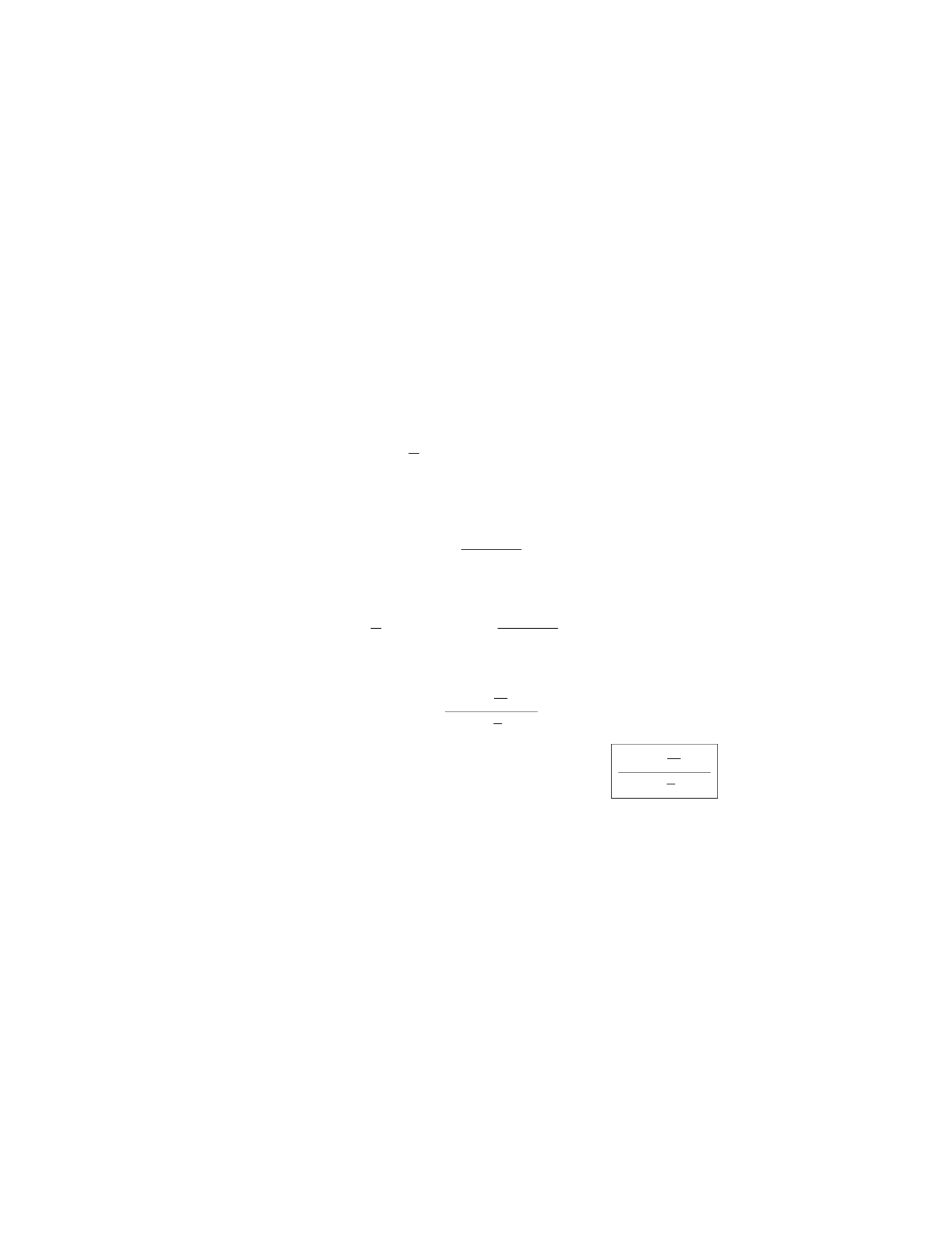
Step 1: Write the force balance equation In the vertical direction:
Tcos(θ) = Mg +W
In the horizontal direction:
Tsin(θ)=0
Step 2: Write the torque balance equation We will take the torque
about the pivot point located at the point where the beam is attached to the
cable. The torque due to the weight Wis zero since it acts right at the pivot
point. The torque due to the beam’s weight (Mg) provides a counterclockwise
torque.
(Mg)L
2−xsin(θ) = Tsin(θ)·x
Step 3: Solve for the tension in the cable From the vertical force
balance equation, we have
T=Mg +W
cos(θ)
Substitute this expression for Tinto the torque balance equation:
(Mg)L
2−xsin(θ) = Mg +W
cos(θ)sin(θ)·x
Simplify and solve for T:
T=(M+W
g)gx
cos(θ)(L
2−x)
Therefore, the expression for the tension in the cable is (M+W
g)gx
cos(θ)(L
2−x).
Question 31
Question
A 2.0 m long copper rod with a circular cross-section has a radius of 1.0 cm.
The rod is stretched by applying a force of 500 N perpendicular to its ends. If
the Young’s modulus of copper is 1.2×10¹¹ N/m2, determine the elongation of
the rod.
26
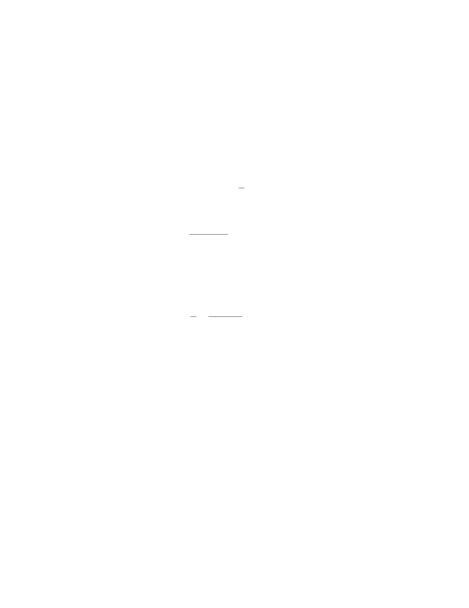
Solution
Step 1: Find the cross-sectional area of the rod using the given radius. Since the
cross-section of the rod is circular, the area can be calculated using the formula
for the area of a circle: πr2. Given that the radius is 1.0 cm (or 0.01 m), the
area is:
A=π(0.01)2= 3.14 ×10⁻⁴m2
Step 2: Calculate the stress on the rod. The stress (σ) on the rod can be
calculated using the formula:
σ=F
A
Substitute the given force (F= 500 N) and the calculated area (A= 3.14×10⁻⁴
m2) into the formula:
σ=500
3.14 ×10−4= 1.59 ×10⁶N/m2
Step 3: Use Hooke’s Law to find the strain in the rod. Hooke’s Law states
that stress is directly proportional to strain (ϵ) by the Young’s modulus of the
material (Y):
σ=Y ϵ
Rearrange the formula to solve for strain:
ϵ=σ
Y=1.59 ×10⁶
1.2×1011 = 1.33 ×10⁻⁵
Step 4: Calculate the elongation of the rod. The elongation can be found
using the formula:
∆L=ϵ·L
Substitute the calculated strain (ϵ= 1.33 ×10⁻⁵) and the original length of the
rod (L= 2.0 m) into the formula:
∆L= 1.33 ×10−5·2.0=2.66 ×10⁻⁵m
Therefore, the elongation of the copper rod is 2.66 ×10⁻⁵m.
Question 32
Question
A uniform, hollow, cylindrical beam of length Land mass Mhangs vertically
from one end, supported by a horizontal cable attached to the other end. If
the tension in the cable is T, what is the force the beam exerts on the cable
(magnitude and direction) and what is the bending moment at the wall where
the cable is attached?
27

Solution
Step 1: Let’s calculate the center of mass of the beam first. The center of mass
of a uniform object is at its geometrical center. For a hollow cylinder, the center
of mass is at a distance L/2 from the end where the cable is attached.
Step 2: Find the gravitational force acting on the beam. The gravitational
force Fgon the beam is given by Fg=M·g, where gis the acceleration due to
gravity.
Step 3: Set up the equilibrium equations. In equilibrium, the sum of forces
in the vertical direction is zero and the sum of torques about any point is zero.
Step 4: Sum of forces in the vertical direction.
T−Fg= 0
T=Fg=M·g
Therefore, the tension in the cable is T=M·gand it acts upward.
Step 5: Calculate the bending moment at the wall. The bending moment at
the wall is the torque created by the gravitational force acting at the center of
mass of the beam.
The torque (τ) is given by τ=F·r, where Fis the force (in this case, Fg),
and ris the distance from the point of rotation (attachment point of the cable)
to the line of action of the force (center of mass of the beam).
τ=Fg·L
2=M·g·L
2
Therefore, the bending moment at the wall where the cable is attached is
M·g·L
2.
Question 33
Question
A rod of length Land uniform cross-sectional area Ais fixed at one end and
hangs vertically. A mass mis attached to the free end. If the young’s modulus
of the material of the rod is Y, what is the force exerted by the rod on the mass
when the mass is in equilibrium? Assume the rod has negligible mass.
Solution
Step 1: Let’s start by drawing a free-body diagram of the forces acting on the
mass when it is in equilibrium:
- The weight of the mass m,mg, acting downwards. - The force exerted by
the rod on the mass F, acting upwards. - The tension in the rod which exerts
a force on the mass, T.
Step 2: Since the mass is in equilibrium, the net force acting on it is zero.
This gives us the equation:
28

T−mg = 0
Step 3: Now we need to find an expression for T, the tension in the rod.
From Hooke’s Law, the stress in the rod is given by σ=F
Aand the strain is
given by ϵ=∆L
L. These are related by Young’s Modulus as σ=Y ϵ.
Step 4: The stress in the rod is F
Aand the strain is L
L(the whole length of
rod). So, we have:
F
A=YL
L
Step 5: Rearranging the equation, we find:
F=Y AL
L=Y A
Step 6: Plugging this into the equation from Step 2, we get:
Y A −mg = 0
Step 7: Solving for F, the force exerted by the rod on the mass, we find:
F=mg
So, the force exerted by the rod on the mass when it is in equilibrium is mg.
Question 34
Question
A uniform beam of length Land mass Mis supported by a pivot at one end
and a cable attached xmeters from the other end. The beam makes an angle
θwith the horizontal. If the tension in the cable is T, determine the tension in
another cable attached ymeters from the pivot.
Solution
Step 1: Draw a free body diagram of the beam.
Identify the forces acting on the beam: the weight mg acting at the center
of mass, the tension in the cable at xmeters, and the tension in the cable
at ymeters.
Decompose the weight into components parallel and perpendicular to the
beam.
29

Step 2: Write down the torque equation about the pivot point. The equation
for equilibrium is
Xτ= 0
The torque due to the weight about the pivot is 0 since its line of action passes
through the pivot. Let’s assume the distance from the pivot to the weight’s
center of mass is c. The torque due to the tension at xis T·(L−x) sin θ, and
the torque due to the tension at yis T′·(L−y) sin θ. Set the sum of torques
equal to zero and solve for T′.
Step 3: Apply the equilibrium condition in the vertical direction. The sum
of vertical forces is zero, so
Tcos θ+T′cos θ=mg
Substitute the value of T′obtained from the torque equation and solve for T′
in terms of known quantities.
Question 35
Question
A uniform rod of length Land mass Mis supported horizontally by two massless
strings attached at each end, making angles θ1and θ2with the horizontal. If
θ1> θ2, determine the tension in each string.
Solution
1. Draw a free-body diagram of the rod. The forces acting on the rod are the
tension forces in the two strings (T1and T2) and the gravitational force acting
at the center of mass of the rod.
2. Break the gravitational force into its components. The vertical component
is Mg and the horizontal component is 0 since the rod is horizontal.
3. Write the force balance equations in the x and y directions:
XFx=0: T1cos θ1=T2cos θ2
XFy=0: T1sin θ1+T2sin θ2=Mg
4. Solve the equations by dividing the second equation by the first to elimi-
nate T2:T1sin θ1+T2sin θ2
T1cos θ1
=Mg
T1cos θ1
5. Use trigonometric identities to simplify the equation:
tan θ1+ tan θ2=Mg
T1
30
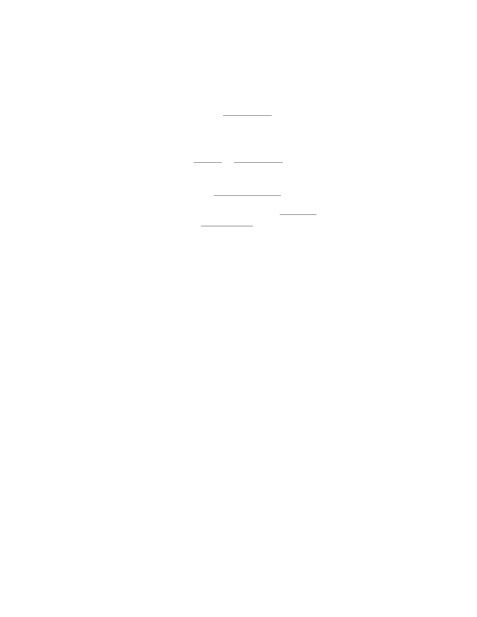
6. Solve for T1:
T1=Mg
tan θ1+ tan θ2
7. Substitute the value of T1back into the force balance equation in the
x-direction to find T2:
T2cos θ2
cos θ1
=Mg
tan θ1+ tan θ2
8. Solve for T2:
T2=Mg cos θ2tan θ1
cos θ1−sin θ1tan θ2
Therefore, the tension in the first string is T1=Mg
tan θ1+tan θ2and the tension
in the second string is T2=Mg cos θ2tan θ1
cos θ1−sin θ1tan θ2.
31

