


Lab - Configure Basic Router Settings
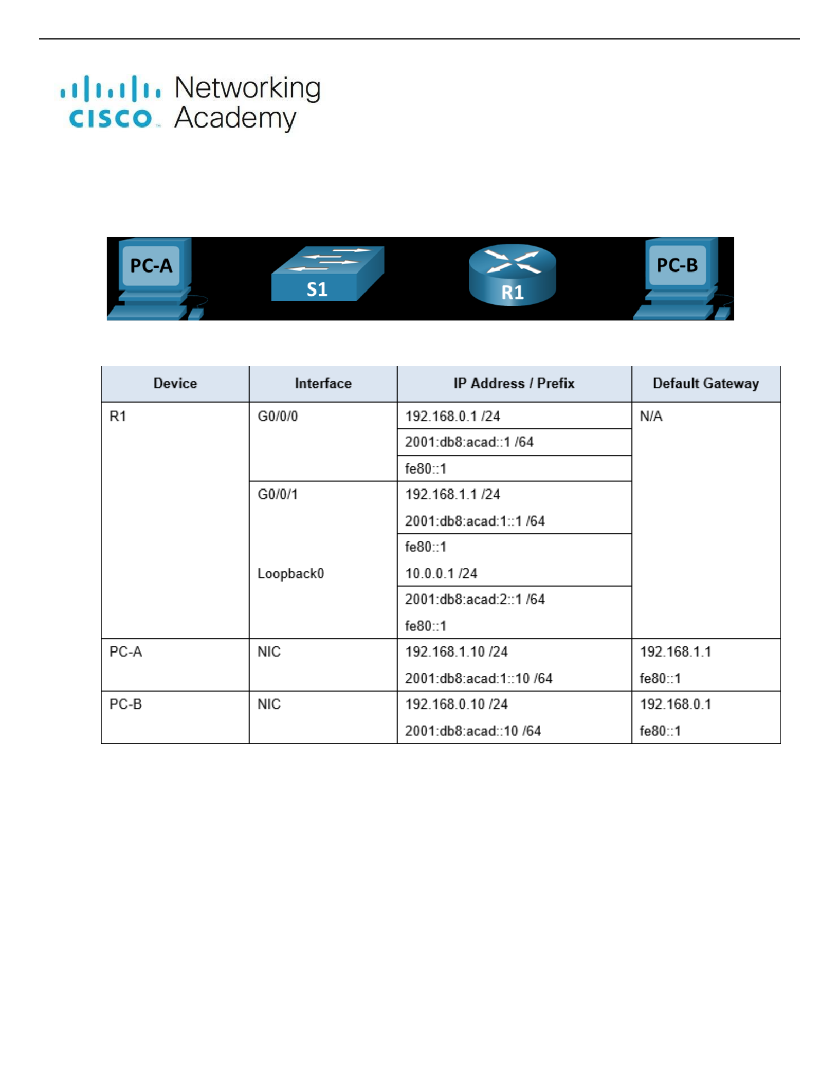
Topology
Addressing Table
Objectives
Part 1: Set Up the Topology and Initialize Devices
• Cable equipment to match the network topology.
• Initialize and restart the router and switch.
Part 2: Configure Devices and Verify Connectivity
• Assign static IPv4 and IPv6 information to the PC interfaces.
• Configure basic router settings.
• Configure the router for SSH.
• Verify network connectivity.

Lab - Configure Basic Router Settings
Part 3: Display Router Information
• Retrieve hardware and software information from the router.
• Interpret the output from the startup configuration.
• Interpret the output from the routing table.
• Verify the status of the interfaces.
Background / Scenario
This is a comprehensive lab to review previously covered IOS router commands. In Parts 1 and 2, you will cable the
equipment and complete basic configurations and interface settings on the router.
In Part 3, you will use SSH to connect to the router remotely and utilize the IOS commands to retrieve information from
the device to answer questions about the router.
For review purposes, this lab provides the commands necessary for specific router configurations.
Note: The routers used with CCNA hands-on labs are Cisco 4221 with Cisco IOS XE Release 16.9.4 (universalk9
image). The switches used in the labs are Cisco Catalyst 2960s with Cisco IOS Release 15.2(2) (lanbasek9 image).
Other routers, switches, and Cisco IOS versions can be used. Depending on the model and Cisco IOS version, the
commands available and the output produced might vary from what is shown in the labs. Refer to the Router Interface
Summary Table at the end of the lab for the correct interface identifiers.
Note: Make sure that the router and switch have been erased and have no startup configurations. Consult with your
instructor for the procedure to initialize and reload a router and switch.
Required Resources
• 1 Router (Cisco 4221 with Cisco IOS XE Release 16.9.4 universal image or comparable)
• 1 Switch (Cisco 2960 with Cisco IOS Release 15.2(2) lanbasek9 image or comparable)
• 2 PCs (Windows with a terminal emulation program, such as Tera Term)
• Console cables to configure the Cisco IOS devices via the console ports
• Ethernet cables as shown in the topology
Note: The Gigabit Ethernet interfaces on Cisco 4221 routers are autosensing and an Ethernet straightthrough cable may
be used between the router and PC-B. If using another model Cisco router, it may be necessary to use an Ethernet
crossover cable.
Instructions Part 1: Set Up the Topology and Initialize Devices
Step 1: Cable the network as shown in the topology.
a. Attach the devices as shown in the topology diagram, and cable as necessary.
b. Power on all the devices in the topology.
Step 2: Initialize and reload the router and switch.
Part 2: Configure Devices and Verify
Connectivity
Step 1: Configure the PC interfaces.
a. Configure the IP address, subnet mask, and default gateway settings on PC-A.
b. Configure the IP address, subnet mask, and default gateway settings on PC-B.

Lab - Configure Basic Router Settings
Step 2: Configure the router.
a. Console into the router and enable privileged EXEC mode.
b. Enter configuration mode.
c. Assign a device name to the router.
d. Set the router’s domain name as ccna-lab.com.
e. Disable DNS lookup to prevent the router from attempting to translate incorrectly entered commands as though
they were host names.
f. Encrypt the plaintext passwords.
g. Configure the system to require a minimum 12-character password.
h. Configure the username SSHadmin with an encrypted password of 55Hadm!n2020.
i. Generate a set of crypto keys with a 1024 bit modulus
j. Assign the privileged EXEC password to $cisco!PRIV*
k. Assign $cisco!!CON* as the console password, configure sessions to disconnect after four minutes of inactivity,
and enable login.
l. Assign $cisco!!VTY* as the vty password, configure the vty lines to accept SSH connections only,
configure sessions to disconnect after four minutes of inactivity, and enable login using the local database.
m. Create a banner that warns anyone accessing the device that unauthorized access is prohibited. n.
Enable IPv6 Routing
o. Configure all three interfaces on the router with the IPv4 and IPv6 addressing information from the
addressing table above. Configure all three interfaces with descriptions. Activate all three interfaces.
p. The router should not allow vty logins for two minutes if three failed login attempts occur within 60
seconds.
q. Set the clock on the router.
r. Save the running configuration to the startup configuration file.
What would be the result of reloading the router prior to completing the copy running-config startupconfig
command?
***Answer all of the questions with ***
Step 3: Verify network connectivity.
a. Using the command line at PC-A, ping the IPv4 and IPv6 addresses for PC-B.
Note: It may be necessary to disable the PCs firewall.
Were the pings successful? Yes
b. Remotely access R1 from PC-A using the Tera Term SSH client.
Using Tera Term on PC-A, open an SSH session to the R1 Loopback interface IPv4 address. Ensure that the SSH
radio button is selected and then click OK to connect to the router. Log in as SSHadmin with the password
55Hadm!n2020.

Lab - Configure Basic Router Settings
Was remote access successful? Yes
Using Tera Term on PC-A, open an SSH session to the R1 Loopback interface IPv6 address. Ensure that the SSH
radio button is selected and then click OK to connect to the router. Log in as SSHadmin with the password
55Hadm!n2020. Note: The IPv6 address should be surrounded with square brackets, i.e. [IPv6 address]
Was remote access successful? Yes
Why is the Telnet protocol considered to be a security risk? A Telnet session can be seen in clear text, it is not
encrypted. Passwords can easily be seen using a packet sniffer.
Part 3: Display Router Information
In Part 3, you will use show commands from an SSH session to retrieve information from the router.
Step 1: Establish an SSH session to R1.
Using Tera Term on PC-B, open an SSH session to the R1 Loopback interface IPv6 address and log in as
SSHadmin with the password 55Hadm!n2020.
Step 2: Retrieve important hardware and software information.
a. Use the show version command to answer questions about the router.
What is the name of the IOS image that the router is running? Isr4300-universalk9.03.16.05.s.155-3.s5- ext.SPA.bin
How much non-volatile random-access memory (NVRAM) does the router have? 32768K of non-volatile configuration
memory.
How much Flash memory does the router have? 3223551K of flash memory.
b. The show commands often provide multiple screens of outputs. Filtering the output allows a user to display certain
sections of the output. To enable the filtering command, enter a pipe (|) character after a show command, followed
by a filtering parameter and a filtering expression. You can match the output to the filtering statement by using the
include keyword to display all lines from the output that contain the filtering expression. Filter the show version
command, using show version | include register to answer the following question.
What is the boot process for the router on the next reload? In most cases (0x2102), the router will undergo a normal
boot, load the IOS from the flash memory, and load the startup configuration from the NVRAM.
Step 3: Display the startup configuration.
Use the show startup-config command on the router to answer the following questions.

Lab - Configure Basic Router Settings
How are passwords presented in the output? Passwords are encrypted due to the service password- encryption command.
Use the show startup-config | section vty command.
What is the result of using this command? Shows the entire section that starts with the filtering expression.
Step 4: Display the routing table on the router.
Use the show ip route command on the router to answer the following questions.
What code is used in the routing table to indicate a directly connected network? The “C” designates a directly connected
subnet.
How many route entries are coded with a C code in the routing table? 3
Step 5: Display a summary list of the interfaces on the router.
a. Use the show ip interface brief command on the router to answer the following question.
What command changed the status of the Gigabit Ethernet ports from administratively down to up? “No shutdown”
b. Use the show ipv6 int brief command to verify IPv6 settings on R1.
What is the meaning of the [up/up] part of the output? It reflects the layer 1 and layer 2 status of the interface and
does not rely on layer 3 for status.
c. On PC-B, change its configuration so that it no longer has a static IPv6 address. You may have to reboot the
machine. Then, issue the ipconfig command on PC-B to examine the IPv6 configuration.
What is the IPv6 address assigned to PC-B? 2001:db8:acad::10
What is the default gateway assigned to PC-B? 2001:db8:acad::1
Issue a ping from PC-B to the R1 default gateway link local address. Was it successful? Yes
Issue a ping from PC-B to the R1 IPv6 unicast address 2001:db8:acad::1. Was it successful? Yes
Reflection Questions
1. In researching a network connectivity issue, a technician suspects that an interface was not enabled. What show
command could the technician use to troubleshoot this issue? Either “show ip interface brief” or “show startup-config”
would work.
Lab - Configure Basic Router Settings
2. In researching a network connectivity issue, a technician suspects that an interface was assigned an incorrect subnet
mask. What show command could the technician use to troubleshoot this issue? “show startup-config” or “show
running-config”
Router Interface Summary Table
Router Model
Ethernet Interface #1
Ethernet Interface #2
Serial Interface #1
Serial Interface #2
1800
Fast Ethernet 0/0
(F0/0)
Fast Ethernet 0/1
(F0/1)
Serial 0/0/0 (S0/0/0)
Serial 0/0/1 (S0/0/1)
1900
Gigabit Ethernet 0/0
(G0/0)
Gigabit Ethernet 0/1
(G0/1)
Serial 0/0/0 (S0/0/0)
Serial 0/0/1 (S0/0/1)
2801
Fast Ethernet 0/0
(F0/0)
Fast Ethernet 0/1
(F0/1)
Serial 0/1/0 (S0/1/0)
Serial 0/1/1 (S0/1/1)
2811
Fast Ethernet 0/0
(F0/0)
Fast Ethernet 0/1
(F0/1)
Serial 0/0/0 (S0/0/0)
Serial 0/0/1 (S0/0/1)
2900
Gigabit Ethernet 0/0
(G0/0)
Gigabit Ethernet 0/1
(G0/1)
Serial 0/0/0 (S0/0/0)
Serial 0/0/1 (S0/0/1)
4221
Gigabit Ethernet 0/0/0
(G0/0/0)
Gigabit Ethernet 0/0/1
(G0/0/1)
Serial 0/1/0 (S0/1/0)
Serial 0/1/1 (S0/1/1)
4300
Gigabit Ethernet 0/0/0
(G0/0/0)
Gigabit Ethernet 0/0/1
(G0/0/1)
Serial 0/1/0 (S0/1/0)
Serial 0/1/1 (S0/1/1)
Note: To find out how the router is configured, look at the interfaces to identify the type of router and how many interfaces
the router has. There is no way to effectively list all the combinations of configurations for each router class. This table
includes identifiers for the possible combinations of Ethernet and Serial interfaces in the device. The table does not include
any other type of interface, even though a specific router may contain one. An example of this might be an ISDN BRI
interface. The string in parenthesis is the legal abbreviation that can be used in Cisco IOS commands to represent the
interface.

