


BMIS 520
Contents
General Instructions.........................................................................................................................2
Compliant Screenshot Example and Instructions............................................................................3
Honesty Statement Instructions.......................................................................................................4
Part 1 Assignment............................................................................................................................5
Assignment Requirements...........................................................................................................5
Assignment Network Topology (From Diaz, 2018)....................................................................7
Example Configurations (From Diaz, 2018)...............................................................................8
Part 2 Assignment..........................................................................................................................10
Assignment Requirements.........................................................................................................10
Assignment Network Topology (From Diaz, 2018)..................................................................11
Example Configurations (From Diaz, 2018).............................................................................13
Final working example configuration of VLANs......................................................................16
Page 1 of 18

BMIS 520
General Instructions
1) Unzip the file PacketTracerAndLabs.zip under "IT Infrastructure Project Assignments".
2) In the zip file PacketTracerAndLabs.zip, install Packet Tracer using the .exe file “Cisco
Packet Tracer 6.2 for Windows Student Version.exe”.
3) Open the PDF in the zip file for an introduction to Packet Tracer.
4) You must use the Packet Tracer version 6.2, provided in the Project instructions zip
file. Instructors cannot open other versions due to licensing and will not be able to open
incompatible versions, resulting in loss of points.
5) Take progressive screenshots that show completion of your work in Packet Tracer. Please
see the example screenshot for how to create proper screenshots for your assignments and
projects.
6) Leave all passwords blank on devices in Packet Tracer so that your assignment can be
graded properly.
7) Complete all assignment deliverables in one (1) Cisco Packet Tracer file.
8) Submit your one (1) Packet Tracer file for credit.
9) Submit one (1) Microsoft Word document with your honesty statement, compliant
screenshots, and all references used.
10) Submit each file individually - no compressed or zipped files will be received for credit.
Page 2 of 18
BMIS 520
Compliant Screenshot Example and Instructions
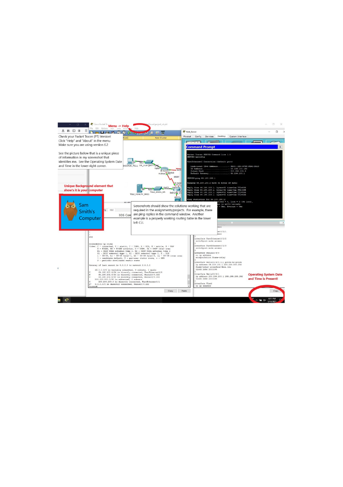
Replace the picture that identifies you with an authentic picture not found on the Internet.
Include multiple side by side windows of routers, switches, PCs, etc. For example, show the
before and after routing table of a router to verify your static route or routing protocol
configuration is correct. Ensure the screenshot is visible, includes all elements in the example.
Include all screenshots in one (1) Microsoft Word document and submit this with your
assignment to the learning management system.
Page 3 of 18

BMIS 520
Honesty Statement Instructions
Completed by Amy Smith on <Include Date Here>
Honesty Statement
I, Amy Smith, did not copy any of the following writing or designs or configurations or code
from any source. I did not use any automated tools, artificial intelligence, or person to assist in
any way in completing this work. All writing, design work, configurations, and code is 100% my
own, original, and created solely for this class. Less than 5% of this work contains direct quotes
or paraphrases. I agree to receive an academic violation if TurnItIn and/or SafeAssign matches
exist of over 10% or I have copied existing Packet Tracer solutions in any form from any person
or source.
Page 4 of 18
BMIS 520
Part 1 Assignment
Unless otherwise specified, the assignment content comes from our Diaz (2018) textbook.
Complete the Diaz (2018) assigned reading to further your understanding of the concepts and
their applications prior to attempting the assignments. In addition, depending on prior
networking preparation, additional chapters may be helpful. For example, if you have never
learned subnetting it is advisable to complete the reading on subnetting.
Reference
Diaz, L. (2018). . Packt Publishing. CCNA Routing and Switching 200-125 Certification Guide
ISBN-13: 978-1-78712-788-3.
Assignment Requirements
1. Open a brand new Cisco Packet Tracer file.
2. Create the assignment network topology in Cisco Packet Tracer.
3. Create a minimum of four (4) local area networks (LANs).
4. Each LAN requires a minimum of one (1) switch and two (2) laptops/PCs.
5. Use proper NIC hardware for each port and assign proper cables between the devices.
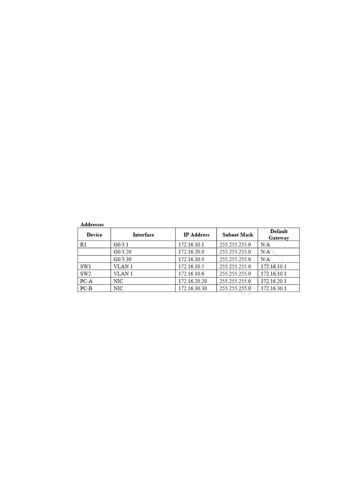
6. Create a spreadsheet in Microsoft Excel and add this to your Microsoft Word document
that shows all devices, interfaces, IP addresses, subnet masks, wildcard masks, default
gateways and any other relevant information. For example:
7. Design and assign proper IP addresses per the topology to all NIC cards on the routers,
switches, and PCs. Use efficient subnets. IPv4 or IPv6 can be used.
8. Label the NIC cards in Packet Tracer with their assigned IP addresses.
9. Try to ping the server from one of the PCs. It will not work unless the routing tables in
the routers know the routes.
10. To ensure routing is working, add proper static routes for all LAN subnets.
11. Once static routing is correct, show proper screenshots that validate the network is
completely functional. All devices should be able to communicate.
Page 5 of 18

BMIS 520
12. *Note, to provide hints and extra help a working example is provided at the end of this
assignment with a topology and configurations.
Page 6 of 18
BMIS 520
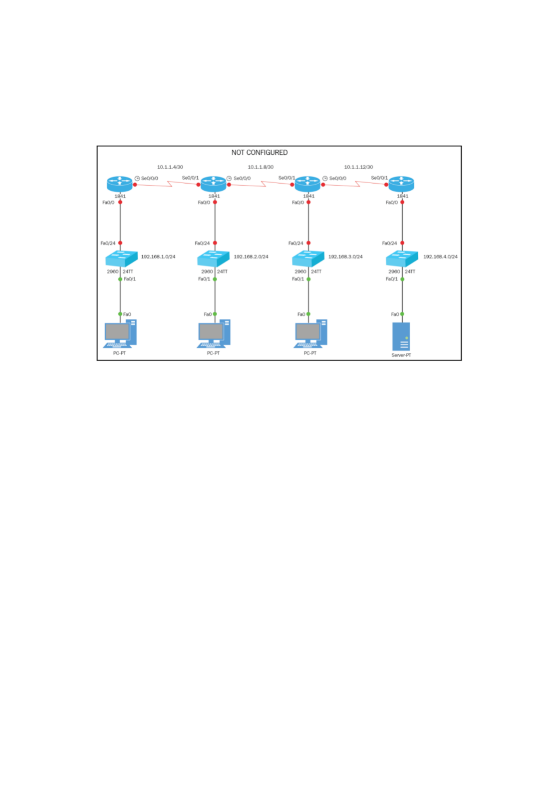
Assignment Network Topology (From Diaz, 2018)
*Note, this is only an example. It is necessary to add to and modify this network topology to
meet the assignment requirements.
Page 7 of 18
BMIS 520
Example Configurations (From Diaz, 2018)
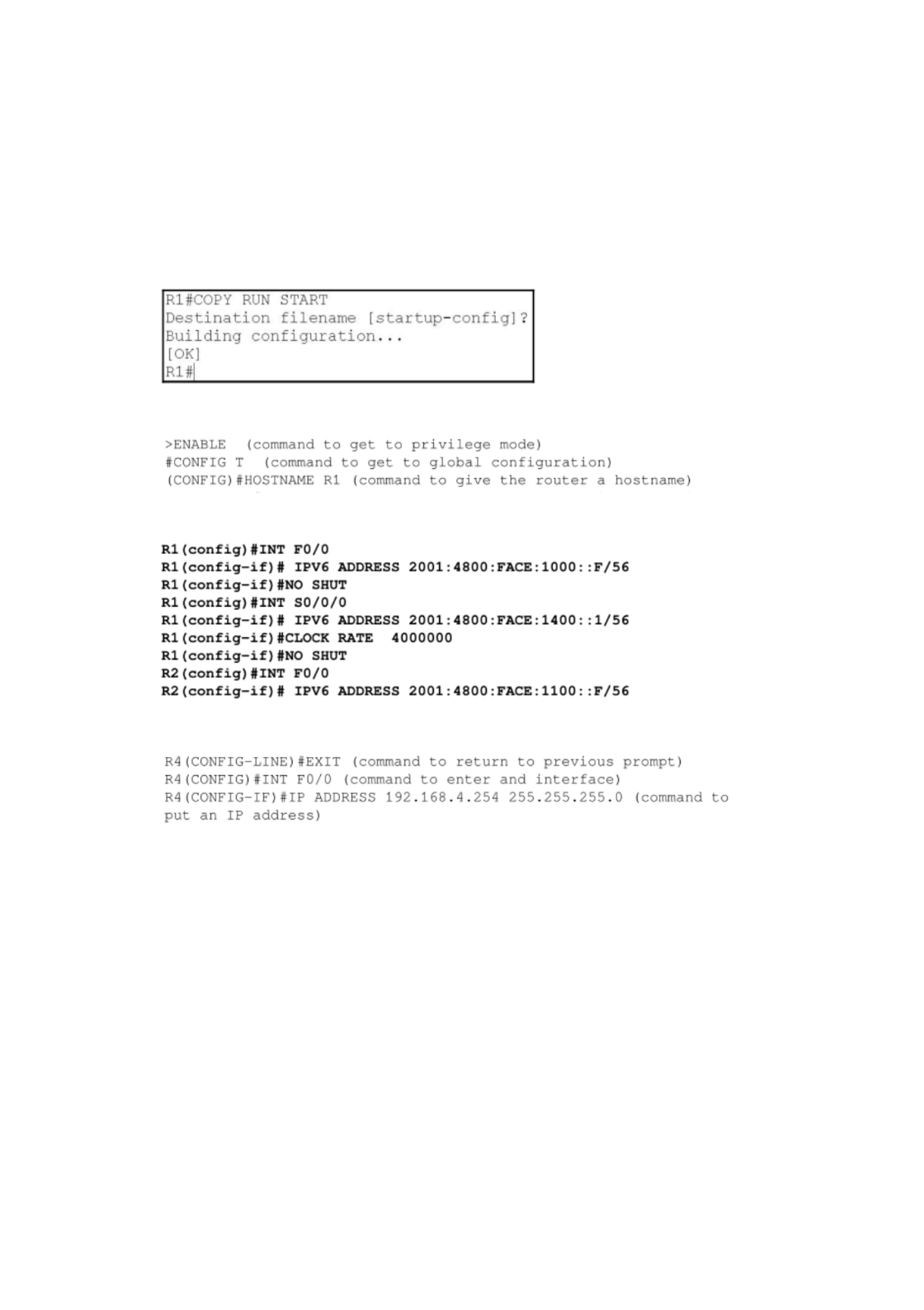
*Note, these are only a few select examples of what should be learned prior to completing the
assignment. This is not comprehensive. All relevant configurations are necessary from the
textbook.
Saving configurations on a router:
Router modes when logging in:
IPv6 NIC assignment on interfaces:
IPv4 NIC assignment on interfaces:
To bring an interface up or enable it:
R4(CONFIG-IF)# no shutdown
To remove a configuration place “no” in front of the original command:
R4(CONFIG-IF)# no ip address 192.168.4.254
Page 8 of 18
BMIS 520
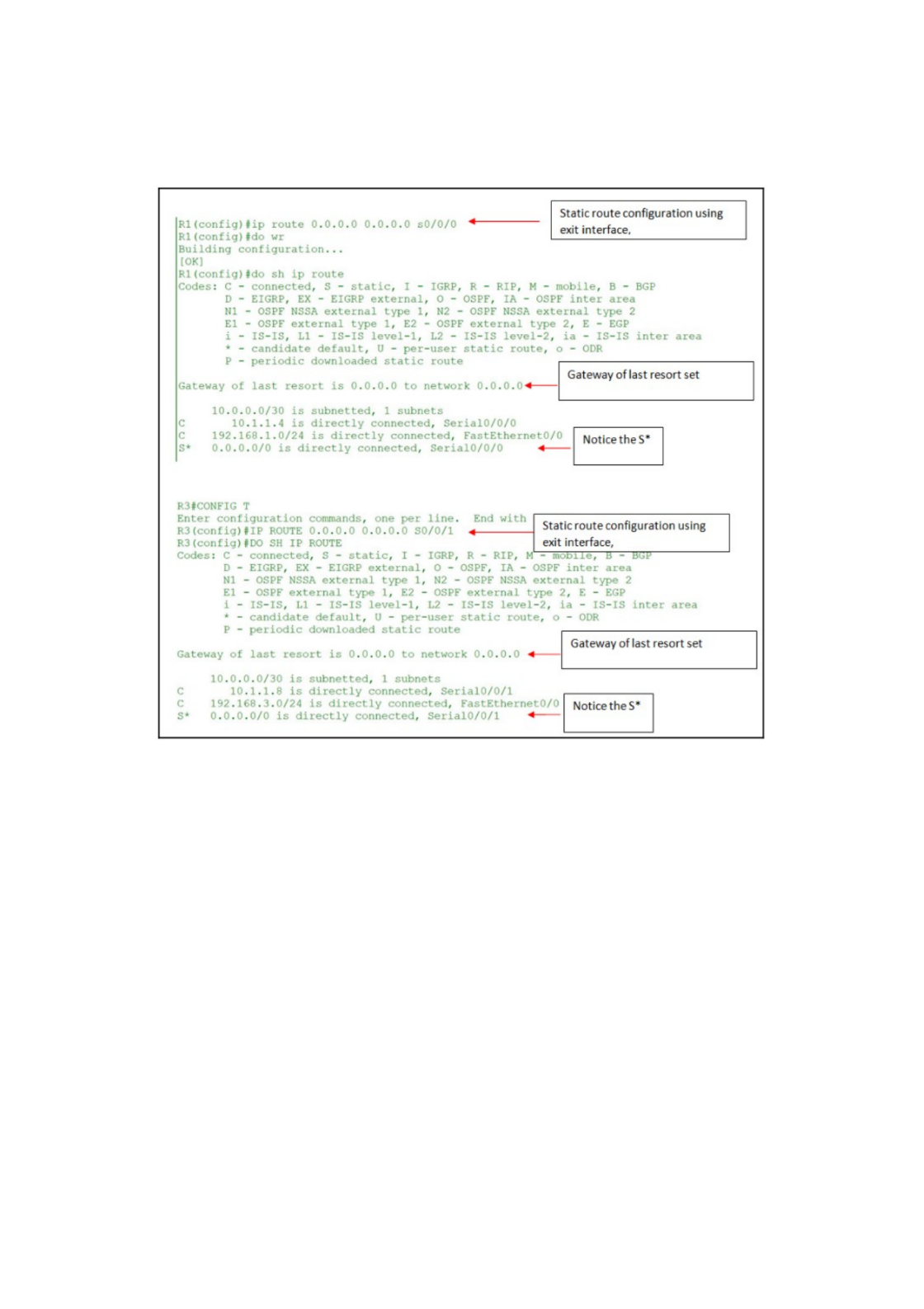
Static route assignment examples:
Once you have these examples completed, create the assignment network topology and apply
what you have learned.
Page 9 of 18
BMIS 520
Part 2 Assignment
Unless otherwise specified, the assignment content comes from our Diaz (2018) textbook.
Complete the Diaz (2018) assigned reading to further your understanding of the concepts and
their applications prior to attempting the assignments. In addition, depending on prior
networking preparation, additional chapters may be helpful.
Reference
Diaz, L. (2018). . Packt Publishing. CCNA Routing and Switching 200-125 Certification Guide
ISBN-13: 978-1-78712-788-3.
Assignment Requirements
1. Add to and modify the part 1 Cisco Packet Tracer file as necessary.
2. Use proper NIC hardware for each port and assign proper cables between the devices.
3. Create a spreadsheet in Microsoft Excel that shows all devices, interfaces, IP addresses,
subnet masks, wildcard masks, default gateways and any other relevant information. Add
the spreadsheet to your Microsoft Word document. For example:
4. Design and assign proper IP addresses per the topology to all NIC cards on the routers,
switches, and PCs. Use efficient subnets. IPv4 or IPv6 can be used.
5. Label the NIC cards in Packet Tracer with their assigned IP addresses.
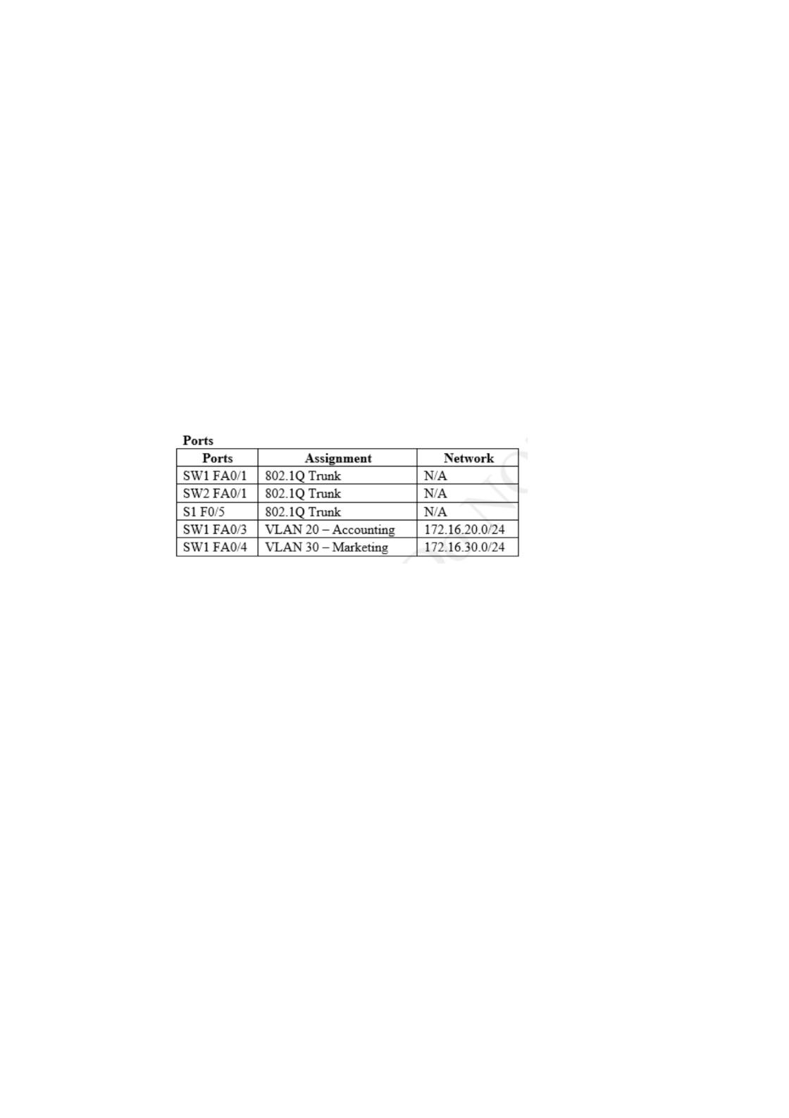
6. Design, create, and implement four (4) VLANs for four (4) business departments such as
the accounting department.
7. Name the VLANs starting with your first and last name, e.g.
<Amy_Smith_Acct_VLAN>
8. Add the VLANs to four (4) routers and four (4) switches.
9. Ensure inter-VLAN routing is working by properly configuring four (4) VLANs to
function across four unique routers.
10. Once this part of the assignment is correct, show proper screenshots that validate all of
the latter deliverables are completely functional.
Page 10 of 18
BMIS 520
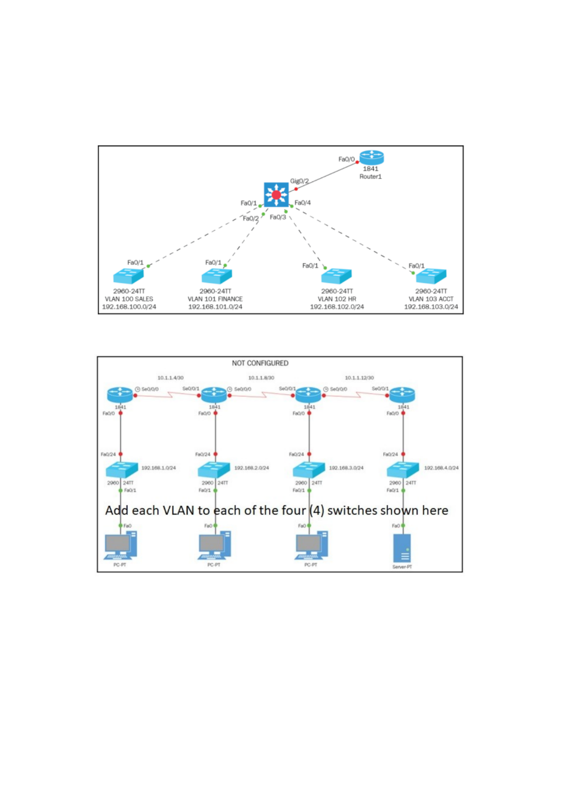
Assignment Network Topology (From Diaz, 2018)
*Note, this is only an example. It is necessary to add to and modify this network topology to
meet the assignment requirements.
Add the VLANs in the latter topology to EACH router in the topology below and ensure inter-
VLAN routing is working between each sub-network.
Page 11 of 18
BMIS 520
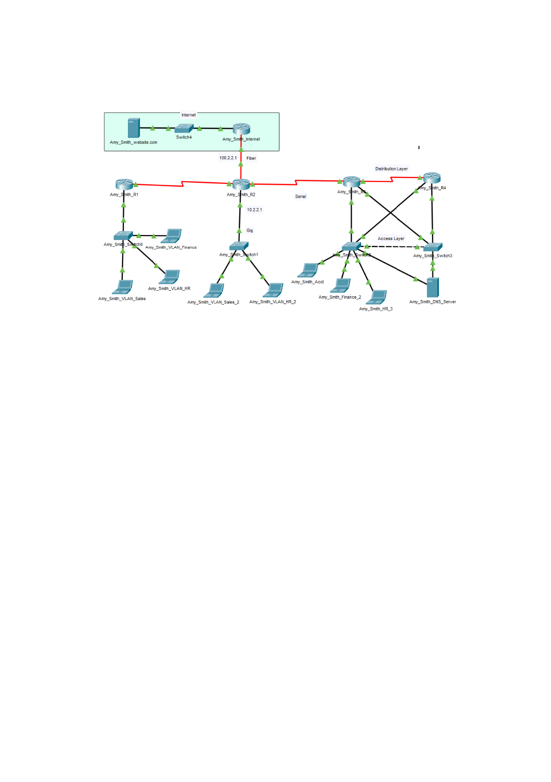
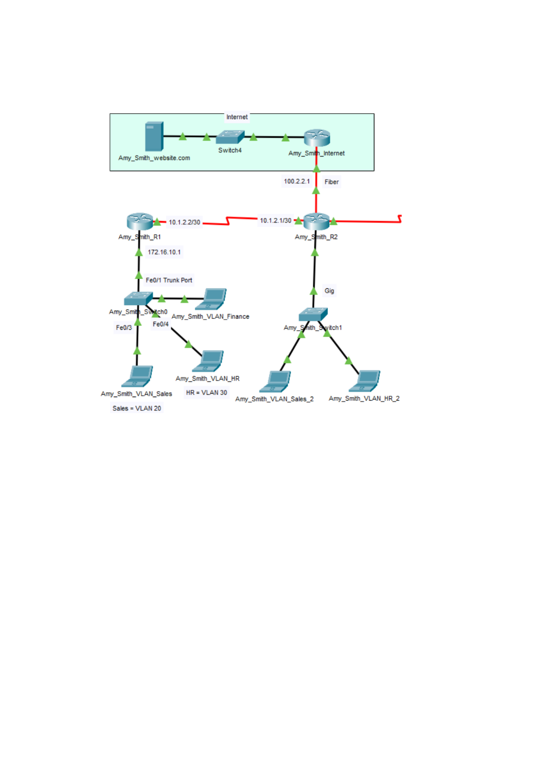
Final working example with inter-VLAN routing, a 2-tier LAN, and an Internet:
Page 12 of 18
BMIS 520
Example Configurations (From Diaz, 2018)
*Note, these are only a few select examples of what should be learned prior to completing the
assignment. This is not comprehensive. All relevant configurations are necessary from the
textbook.
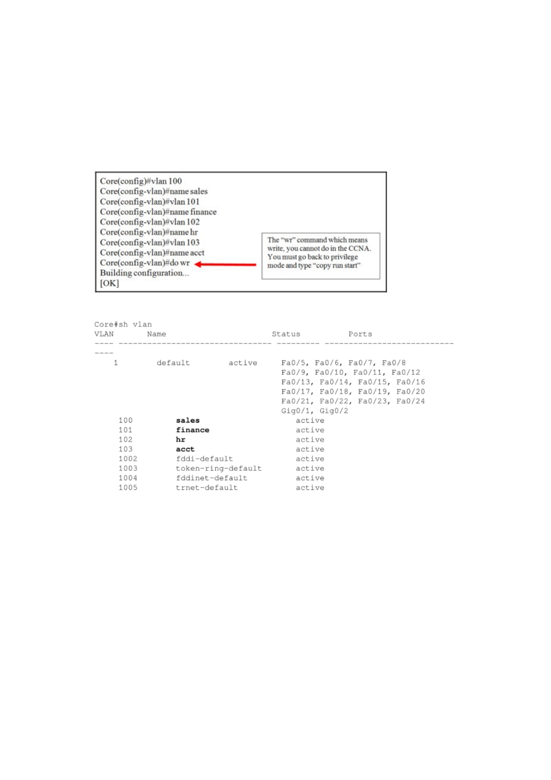
Creating VLANs:
Showing VLANs that are configured:
Page 13 of 18

BMIS 520
Configuring VTP clients:
Page 14 of 18
BMIS 520
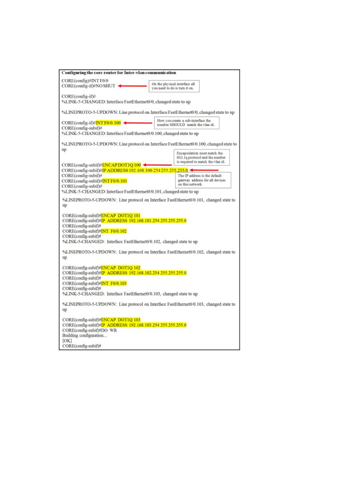
Configuring inter-VLAN routing on routers connected to VLAN enabled switches:
Page 15 of 18
BMIS 520
Final working example configuration of VLANs
This is a step by step example for configuring a new VLAN in the final assignment network
topology. Start by assigning numbers and VLAN descriptions to these numbers on your layer 2
switches:
SW1(config)# vlan 20
SW1(config-vlan)# name Sales
SW1(config-vlan)# vlan 30
SW1(config-vlan)# name HR
Next, configure these same VLANs on subsequent switches in your network. After your VLANs
are configured on your switches, it is necessary to configure connecting routers.
Page 16 of 18

BMIS 520
Step by step example for configuring VLAN 1 on a Router using 801.1Q:
Let's start by configuring a subinterface for VLAN 1. Create a subinterface on the next hop
router connected to SW1. Use the interface connected to your switch. As an example, we can use
G3/0 for VLAN 1 using 1 as the subinterface ID:
• Router(config)# interface g3/0.1
Note, if your router interface is different such as int G0/1, the command would be:
• Router(config)# interface g0/1.1
Next, we configure the subinterface to operate on VLAN 1 using 801.1Q encapsulation:
• Router(config-subif)# encapsulation dot1Q 1
Configure the subinterface with the IP address from the Address Table. Notice, this is often a
default gateway IP address:
• Router(config-subif)# ip address 172.16.10.1 255.255.255.0
Note, if you get an error such as, "172.16.10.0 overlaps with GigabitEthernet3/0". You need to
remove your existing Gig3/0 IP address. As an example:
Router(config-subif)#exit
Router(config)#int Gig3/0
Router(config-if)#no ip address 172.16.10.0 255.255.255.0
Router(config-if)#shutdown
Now, reconfigure your subinterface correctly.
Next, let’s review some example solutions to help you get started.
Switch 0 configuration for Amy_Smith_Switch0:
interface Vlan1
ip address 172.16.10.5 255.255.255.0
ip default-gateway 172.16.10.1
spanning-tree mode pvst
spanning-tree extend system-id
interface FastEthernet0/1
switchport mode trunk
interface FastEthernet0/2
switchport mode trunk
Page 17 of 18

BMIS 520
interface FastEthernet0/3
switchport access vlan 20
switchport mode access
interface FastEthernet0/4
switchport access vlan 30
switchport mode access
Router configuration for Amy_Smith_R1:
interface GigabitEthernet3/0
no ip address
no shutdown
interface GigabitEthernet3/0.1
encapsulation dot1Q 1 native
ip address 172.16.10.1 255.255.255.0
interface GigabitEthernet3/0.20
encapsulation dot1Q 20
ip address 172.16.20.1 255.255.255.0
interface GigabitEthernet3/0.30
encapsulation dot1Q 30
ip address 172.16.30.1 255.255.255.0
ip route 0.0.0.0 0.0.0.0 10.1.2.1 220
Example troubleshooting commands for inter-VLAN routing:
Router# show interfaces trunk
Router# show interfaces switchport
Once you have these examples completed, create the assignment network topology and apply
what you have learned.
Page 18 of 18

