


CSUN COMP 222 Study Notes: The Exclusive NOR (XNOR)
Operation
Course: COMP 222 - Introduction to Digital Logic and Computer Design
Topic: Exclusive NOR (XNOR) - The Equality Checker
I. Introduction and Fundamental Definition
The Exclusive NOR (XNOR) operation, denoted by
A⊙B
, is fundamentally an
equality detector. Unlike the standard OR (
A+B
) or AND (
A⋅B
), which check for the
presence or co-occurrence of inputs, XNOR checks if the inputs are the same.
In logical terms, the output of the XNOR gate is TRUE (Logic 1) if and only if its
inputs are logically equal.
A. Core Properties and Notation
Logical Condition:
Y=1
if
A=B
.
Alternative Names: Equivalence Gate, Coincidence Gate, Even Parity Checker (when
extended to multiple inputs).
Symbols:
Algebraic:
A⊙B
(often written as
A⊕
―
B
or
AXNOR B
).
Schematic: The standard XOR symbol with a negation bubble (inversion bubble) on
the output.
B. The Complementary Relationship to XOR
It is essential to understand that XNOR is simply the complement of the Exclusive
OR (XOR) operation:
A⊙B=A⊕B
―
Since XOR is the "difference detector" (output 1 when inputs are different), XNOR is
the "sameness detector" (output 1 when inputs are the same). This complementary
nature simplifies many algebraic manipulations, particularly when using De
Morgans theorem.
II. Truth Table Analysis and Logical Function
The behavior of the XNOR gate is summarized perfectly in its truth table. The output
is high only for the first (00) and last (11) input combinations.
A. The 2-Input XNOR Truth Table
A B Y=A⊙B Minterm (mi)
0 0 1
m0
0 1 0
m1
1 0 0
m2
1 1 1
m3
Insight: This truth table shows that the function is defined by the minterms
m0
and
m3
. This immediately leads us to the canonical Sum-of-Products (SOP) form.
B. Extended XNOR (3 or More Inputs)
While the 2-input XNOR is a strict equality checker, an extended chain of XNOR
gates (e.g.,
A⊙B⊙C
) is used as an Even Parity Checker.
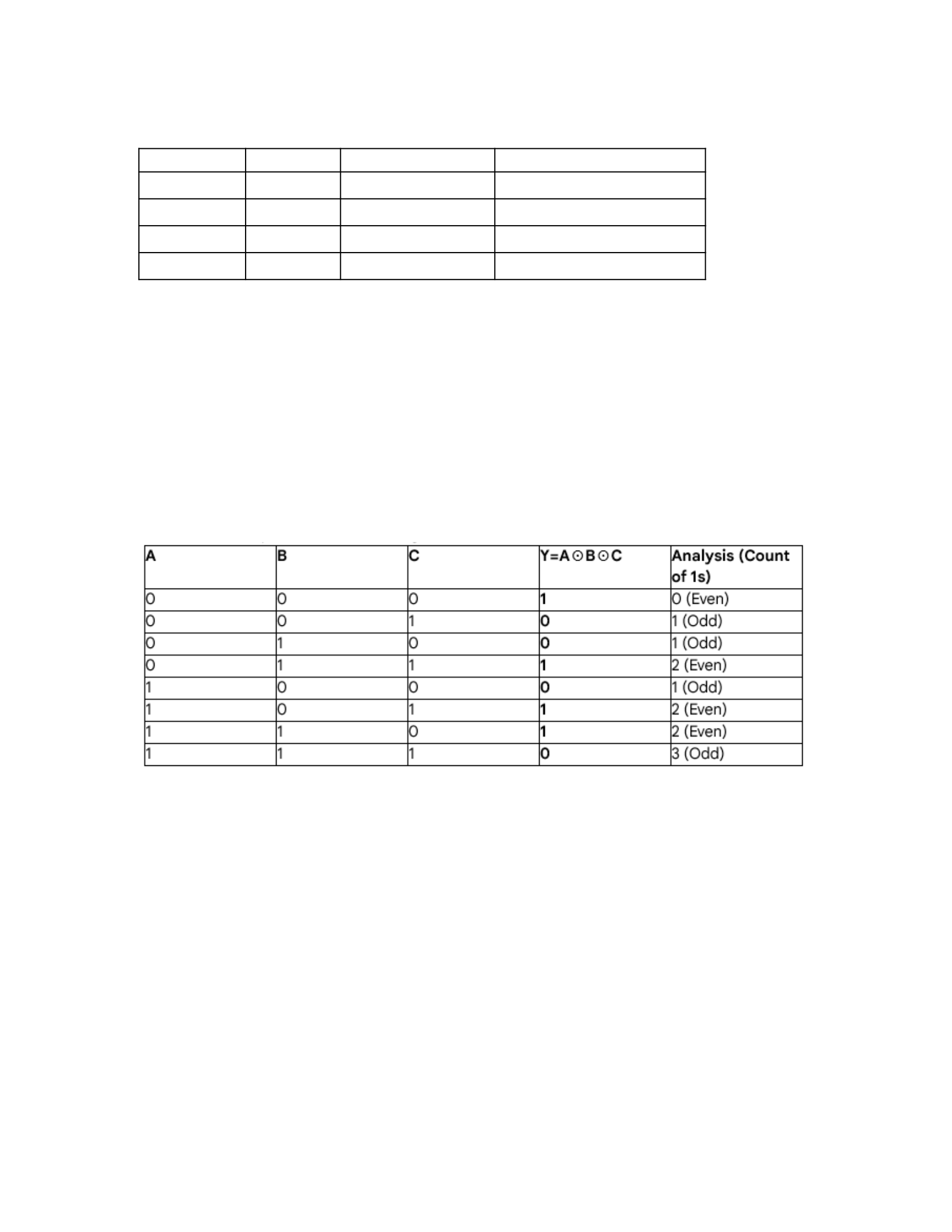
Rule for Multi-Input XNOR: The output is TRUE (Logic 1) if and only if the number of
TRUE (1) inputs is even (including zero).
Pitfall Alert (for the COMP 222 midterm!): Students often mistakenly assume a 3-
input XNOR checks if
A=B=C
. It does not! If
A=1, B=1, C=0
, the output is 1
because the number of 1s (two) is even. A true 3-input equality checker requires
much more complex logic:
A⊙B⋅A⊙C
. Remember, chained XNOR/XOR gates are
Parity Checkers, not general Equality Checkers.
III. Algebraic Representation and Simplification
The algebraic definition of XNOR is critical for understanding its role in larger
systems and for using it in Karnaugh Maps (K-maps).
A. Canonical Sum-of-Products (SOP) Form
Since the output is 1 for minterms
m0
(00) and
m3
(11), the SOP form is:
A⊙B=m0+m3

Expanding the minterms:
A⊙B=A B+AB
This is the most standard and useful algebraic form of XNOR. It clearly shows the
two conditions for an output of 1: (A and B are both 0) OR (A and B are both 1).
B. Product-of-Sums (POS) Form
The POS form is derived from the maxterms (
Mi
) where the output is 0, which are
M1
(01) and
M2
(10).
A⊙B=M1⋅M2
Expanding the maxterms:
A⊙B=(A+B)⋅(A+B)
While the SOP form is generally preferred for implementation (due to ease of
factoring and K-map usage), the POS form gives an interesting perspective: the
output is 0 if (A is 1 OR B is 0) AND (A is 0 OR B is 1).
C. Algebraic Derivation from Complement (Advanced Insight)
We know
A⊙B=A⊕B
―
. We can use De Morgans Law to prove the SOP form from
the XOR SOP form.
Start with the XOR SOP form:
A⊕B=A B+A B
Now, take the complement:
A⊙B=A B+A B
―
Apply De Morgan’s Law to the main sum (
X+Y
―
=X⋅Y
):
A⊙B=A B
―
⋅A B
―
Apply De Morgan’s Law to each term again:
A⊙B=(A+B
―
)⋅(A
―
+B)
Apply Involution (
X
―
=X
):
A⊙B=(A+B)⋅(A+B)
Expand (using Distributive Law / FOIL):
A⊙B=A A+A B+BA+B B

Apply Complement Law (
A A=0
and
B B=0
):
A⊙B=0+A B+AB+0
Final SOP Form:
A⊙B=AB+A B
Analysis: This algebraic proof is crucial. It connects the POS form
(A+B)⋅(A+B)
directly to the SOP form
AB+A B
via expansion, proving the two forms are
equivalent. Its a great example of how all Boolean laws work together.
IV. Hardware Implementation and Cost Analysis
The XNOR gate is not a simple fundamental gate like AND or OR; it requires internal
complexity. This makes it more costly in terms of chip area and propagation delay.
A. Implementing XNOR with Basic Gates
The XNOR function
Y=AB+A B
requires three levels of logic:
Inversion: Two NOT gates to get
A
and
B
.
Product: Two 2-input AND gates (one for
AB
and one for
A B
).
Sum: One 2-input OR gate to combine the products.
Total Gates: 5 basic gates (2 NOT, 2 AND, 1 OR).
B. Implementing XNOR with Universal Gates (NAND/NOR)
In modern integrated circuits (ICs), circuits are often implemented using only
Universal Gates (NAND or NOR) because they are typically easier to manufacture
efficiently.
1. NAND-only Implementation
To implement
Y=AB+A B
using only NAND gates, we use De Morgans law (
X+Y=X
―
⋅Y
¿
) to convert the final OR to a NAND structure:
Y=AB
―
⋅A B
¿
This requires a minimum of 5 NAND gates:
Two NAND gates configured as NOT gates (for
A
and
B
).
Two NAND gates to compute
AB
―
and
A B
―
. (This step uses the NAND gates properties
to simplify the AND terms, often requiring fewer gates than the theoretical
minimum).

One final NAND gate to combine the two intermediate NAND outputs and negate
them (
X
―
⋅Y
―
).
2. CMOS Transistor Count (My Personal Insight)
For a standard static CMOS design:
NOT gate: 2 transistors.
NAND gate: 4 transistors.
NOR gate: 4 transistors.
XOR gate: 6-8 transistors (highly complex).
XNOR gate: Typically requires 8 to 12 transistors.
Since XNOR is implemented as XOR-then-NOT, or often as a specially designed
structure, it is physically large. This high transistor count contributes to increased
propagation delay (
tpd
) and higher power consumption compared to a simple AND
or OR gate. In design optimization, we always try to replace XNORs with simpler
logic where possible, though sometimes the simplicity of the
A⊙B
function is worth
the cost.
V. Critical Applications of the XNOR Gate
The XNOR gates role as an equality detector is foundational to several key
components in computer architecture.
A. The 1-Bit Comparator (The Natural Fit)
The most direct application is the 1-bit magnitude comparator.
Given two bits
A
and
B
, the XNOR output
Y=A⊙B
directly tells us if
A=B
.
If
Y=1
, then
A
is equal to
B
.
If
Y=0
, then
A
is not equal to
B
.
Real-World Application: To compare two
N
-bit numbers (e.g., two 32-bit registers),
we can use
N
parallel 1-bit XNOR gates. The outputs of these XNOR gates are then
fed into a final
N
-input AND gate. Only if all
N
XNOR gates output 1 (meaning every
bit pair is equal) will the final AND gate output 1, indicating the two
N
-bit numbers
are identical.
B. Controlled Buffer / Controlled Inverter
When one input of the XNOR gate is used as a control line (
C
) and the other as a data
line (
D
), the XNOR gate acts as a reconfigurable circuit:
Y=C⊙D=CD +C D
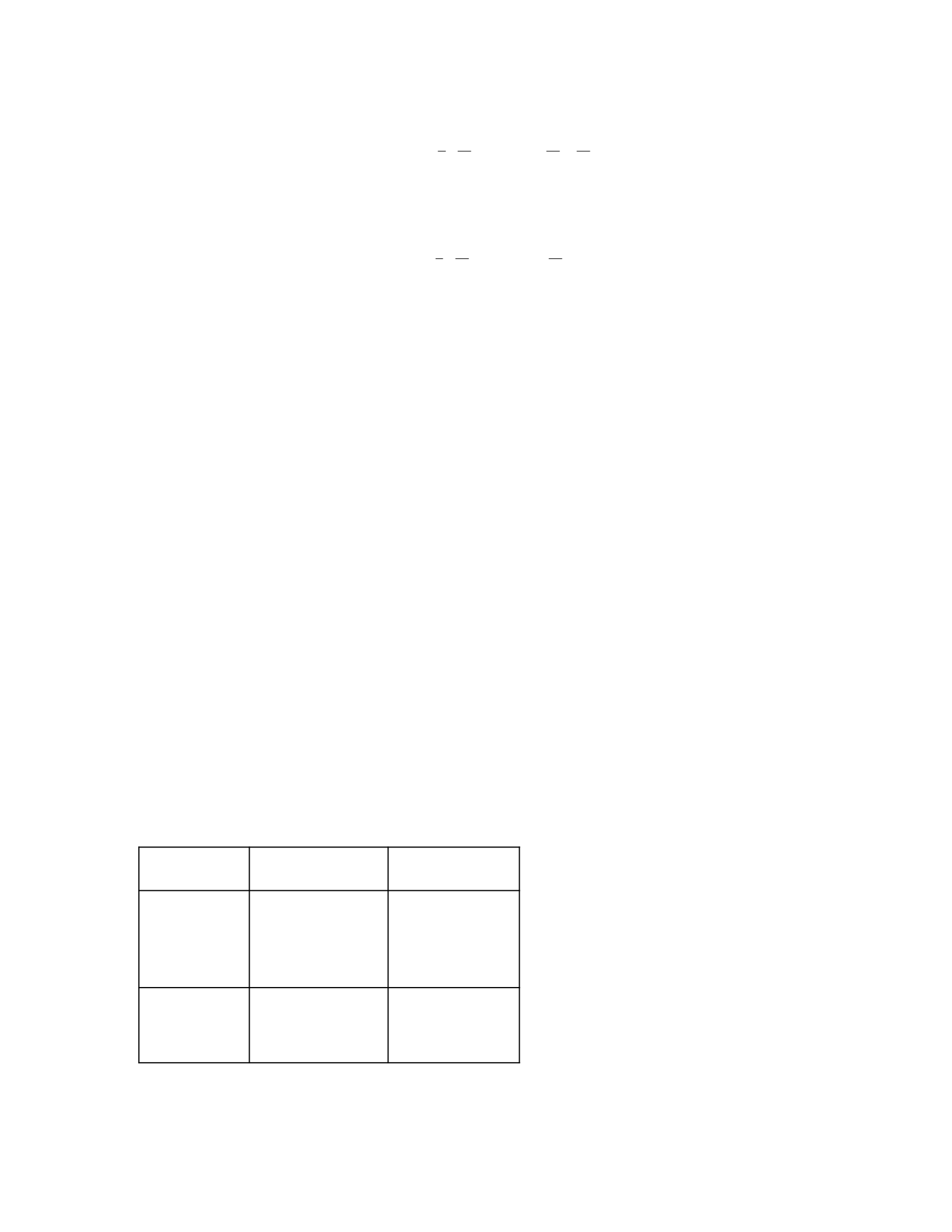
If
C=0
(Control Low):
Y=0⋅D+0⋅DY =0+1⋅D=D
Result: The XNOR gate acts as an Inverter (NOT gate).
If
C=1
(Control High):
Y=1⋅D+1⋅DY =D+0⋅D=D
Result: The XNOR gate acts as a Non-Inverting Buffer.
Insight: This application is crucial in digital systems where a data bus may need to
be selectively inverted or passed through unchanged, such as in arithmetic logic
units (ALUs) for performing ones complement (inversion) during subtraction
operations.
C. Parity Checking
As discussed in Section II, a chain of XNOR gates is used to check the parity of a
block of data.
Even Parity Generator: Creates a Parity Bit
P
such that the total number of 1s in the
data block plus
P
is even. A chain of XOR gates is typically used to generate the
parity bit.
Even Parity Checker: A chain of XNOR gates checks if the received data (including
the parity bit) has an even number of 1s. If the count is even, the output is 1 (no
error detected). If the count is odd, the output is 0 (error detected).
VI. Common Pitfalls and Study Strategy (CSUN Focus)
Based on typical COMP 222 exams and design labs, here are the most common
mistakes students make with the XNOR operation.
A. Pitfall: Confusing XNOR with XOR
This is the single biggest error. Always recall the key difference:
Operation Logical
Function
Minterms (mi
)
XNOR (
A⊙B
)
EQUALITY
m0, m3
XOR (
A⊕B
)DIFFERENCE
m1,m2
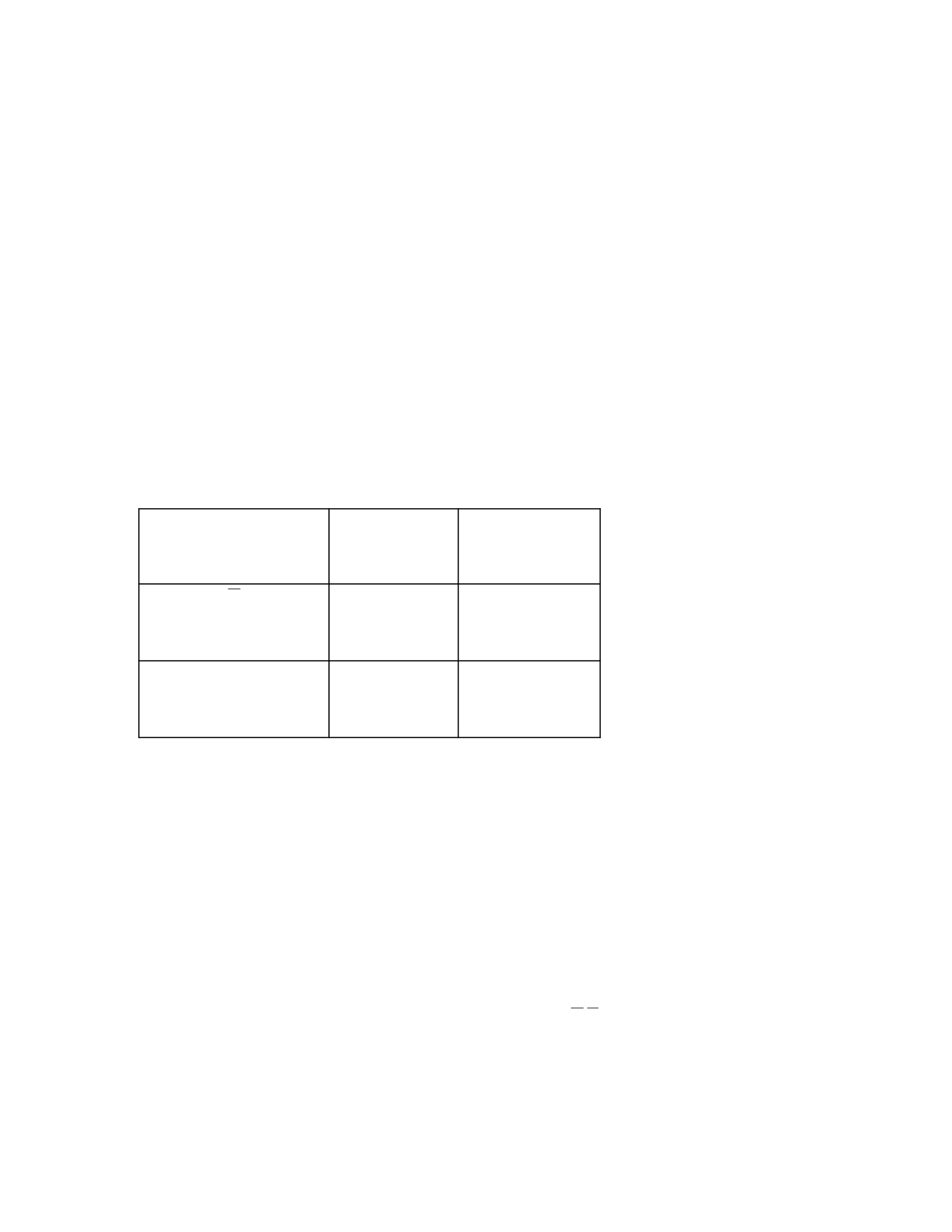
If your design requires two inputs to be exactly the same to activate, use XNOR. If it
requires them to be different, use XOR.
B. Pitfall: Treating Chained XNOR as Equality
As mentioned,
A⊙B⊙C
is a parity checker, not a three-way equality checker (
A=B=C
).
If the exam question asks for a 4-bit equality checker: You must use four separate
XNOR gates, followed by a 4-input AND gate.
If the exam question asks for a 4-bit parity checker: You must use three chained
XNOR or XOR gates.
C. Pitfall: K-map Simplification for XNOR/XOR Functions
XNOR and XOR functions are known for creating a checkerboard pattern on K-maps
(non-adjacent 1s).
For
A⊙B
, the K-map looks like:
Bˉ B
A
1 (
m0
) 0 (
m2
)
A
0 (
m1
) 1 (
m3
)
The crucial strategy here: You cannot circle the 1s in the standard 2x1 or 2x2 groups
because they are diagonally opposite. Always simplify XNOR/XOR functions
algebraically or by inspection, rather than relying on K-map grouping, unless the
XNOR/XOR terms are part of a larger function that allows for grouping with other
adjacent 1s.
D. Pitfall: Incorrect Algebraic Expansion
When simplifying complex expressions that include XNOR, always expand the XNOR
first using its SOP form:
ALWAYS use: X⊙Y=XY +X Y
Example simplification mistake:
(A⊙B)
―
⋅C

Incorrect path: Using
A⊙B
―
as
A⊕B
and then applying De Morgans later is slower.
Correct path: Replace
A⊙B
―
immediately with
A⊕B=A B+A B
:
(A B+A B)⋅C=A B C +A BC
This is much cleaner and avoids multiple negation steps.
E. Study Strategy for COMP 222
Memorize the SOP forms: You must instantly recall
A⊕B=A B+A B
and
A⊙B=AB+A B
. These are non-negotiable foundations.
Practice the Controlled Inverter: This application is highly testable. Practice the
logic when the control line is 0 and when it is 1.
Gate Counting: Be prepared to calculate the total transistor or basic gate count for
an XNOR implementation. Use the 5-gate basic implementation as your worst-case
estimate if not asked for a universal gate design.
VII. Programming Context: Bitwise XNOR
In languages like C, C++, and Java, there is no native Bitwise XNOR operator. This
forces us to implement it using the available Bitwise XOR (^) and Bitwise NOT (~)
operators.
A. Implementing Bitwise XNOR
The XNOR function
A⊙B
is the complement of the XOR function
A⊕B
. In a
programming context, this means:
Bitwise XNOR=Bitwise NOT(Bitwise XOR)Code:∼(A
^
❑B)
Why this matters: When performing comparisons on data words (e.g., checking if
two 32-bit integers
A
and
B
are equal), you first calculate the bitwise XOR. If the
result of
A
^
❑B
is
0
, it means every bit was the same, and
A=B
. The XNOR operation
essentially flips the bits of the XOR result.
B. Bit Masking and Encryption Insight
The XNOR logic is also used in simple data scrambling/encryption, often combined
with XOR.
If a data byte
D
is encrypted using a key
K
via XOR:
Encrypted Data E=D⊕K
To decrypt the data, you apply the same key
K
again:
Decrypted Data D′=E⊕KDecrypted Data D′=(D⊕K)⊕K

Since
K⊕K=0
(a property of XOR), the expression simplifies to
D′=D⊕0=D
.
The XNOR connection: The XNOR gate is the fundamental logic underlying this
decryption process, as it returns 1 only when the encrypted bit and the key bit are
the same, effectively checking for coincidence in the stream.
VIII. Final Reflection
The XNOR gate is often overlooked due to its simplicity, yet it holds one of the most
powerful and intuitive concepts in digital design: coincidence. Mastering the
A B+AB
form and understanding its non-associative nature for strict equality
checking are the hallmarks of a successful COMP 222 student. The high component
count is a physical reminder that true equality detection is always a complex
operation for the simplest of inputs. Focus on the applications—comparators,
controlled inversion, and parity—as these will be the foundation for future courses
in computer architecture.

