


COMP 222: Computer Organization and Assembly
Language
Extended Study Notes: Data Storage: Representation, Organization, and Hierarchy
Student:Amber
Course: COMP 222
Institution: California State University, Northridge (CSUN)
Date: November 20, 2025
I. Learning Insights
Data storage, at its core, is the study of abstraction, quantization, and compromise. My initial
understanding of data types in high-level languages like C++ or Java was naive; I assumed that an
int perfectly represented an integer or a float perfectly represented a real number. COMP 222
dismantled this notion by exposing the architectural constraints underlying every data
representation.
The most profound insight is the realization that Twos Complement is not just an arbitrary
convention, but an elegant design solution that allows the CPU to use the exact same hardware
for addition of both signed and unsigned integers, eliminating the need for separate sign-
checking and subtraction logic. This principle of hardware simplification is a cornerstone of
computer architecture.
Furthermore, the complexity of the IEEE 754 Floating-Point Standard underscores the
compromise between range and precision. The sign, exponent, and significand allocation
demonstrates a deliberate trade-off to maximize the range of representable numbers (via the
exponent) at the expense of evenly distributed precision. The existence of special values like
± ∞
and NaN (Not a Number) highlights how the architecture is designed to handle mathematical
impossibilities gracefully, rather than simply crashing.
Finally, the Memory Hierarchy is a perfect embodiment of the Locality of Reference principle.
Understanding that the system relies on the predictable behavior of software (using data recently
or nearby) to bridge the immense speed gap between the CPU registers (fastest) and the disk
(slowest) is key to writing high-performance code. The entire storage organization, from register
allocation in assembly to cache line transfers, is an optimization problem based on minimizing
this latency gap. Without a deep comprehension of how data is stored and moved, high-level
programming remains a black box.

II. Knowledge Consolidation
Data storage encompasses two major domains: data representation (how bits encode
information) and storage organization (where and how fast data is accessed).
A. Data Representation in Binary Systems
All data, regardless of complexity, must be translated into a binary sequence of
0
s and
1
s for
computer storage and processing.
1. Unsigned Integer Representation
Unsigned integers only represent non-negative numbers. The representation is straightforward
binary-to-decimal conversion. For an
N
-bit system, the range is from
0
to
2N−1
.
Formula: For a binary number
bN − 1bN − 2…b1b0
, the decimal value
V
is:
V = \sum_{i=0}^{N-1} b_i \cdot 2^i
Application: Used primarily for memory addresses, array indices, and byte-level manipulation
where negative values are irrelevant.
2. Signed Integer Representation: Twos Complement
The Twos Complement system is the universal standard for representing signed integers in
modern CPUs because it unifies addition and subtraction.
Sign Bit: The Most Significant Bit (MSB,
bN − 1
) indicates the sign:
0
for non-negative,
1
for
negative.
Range: For an
N
-bit system, the range is from
−2N − 1
to
2N −1−1
. This asymmetric range (one
more negative number than positive) is a unique feature of the system.
Finding the Negative: To find the Twos Complement representation of a negative number
− X
:
Find the binary representation of
X
.
Invert all the bits (perform the Ones Complement).
Add
1
to the result.
Arithmetic Elegance: Addition of twos complement numbers is performed exactly like unsigned
addition, including the sign bits. Any carry-out from the MSB is ignored.
Overflow: In a Twos Complement system, overflow occurs when the result of an addition exceeds
the representable range.
Condition: Overflow is detected if and only if the carry-in to the MSB position is different from
the carry-out from the MSB position.
Example: Adding two large positive numbers resulting in a negative number, or two large negative
numbers resulting in a positive number.
3. Character Representation (ASCII and Unicode)
Character data requires a standard mapping between a numerical code and the character glyph.
ASCII (American Standard Code for Information Interchange):
An older, 7-bit standard, covering
128
characters (letters, numbers, punctuation, control codes).
The 8th bit was often used for parity checking.
Unicode:
A modern, expansive standard designed to include all characters from all written languages
globally.
Uses code points ranging up to
0x10 FFFF
.
UTF-8 (Unicode Transformation Format - 8-bit):
The dominant encoding scheme for Unicode on the internet and most systems.
It is a variable-width encoding:
ASCII characters (0-127) use 1 byte (compatible with traditional ASCII).
Most common non-ASCII characters use 2 or 3 bytes.
Rarer characters use 4 bytes.
Application: Optimizes storage by keeping common Latin characters small while allowing full
international support.
4. Floating-Point Representation (IEEE 754 Standard)
Floating-point numbers (real numbers) are stored using a sign-magnitude representation based
on scientific notation,
V=±(1+Fraction)×2Exponent
.
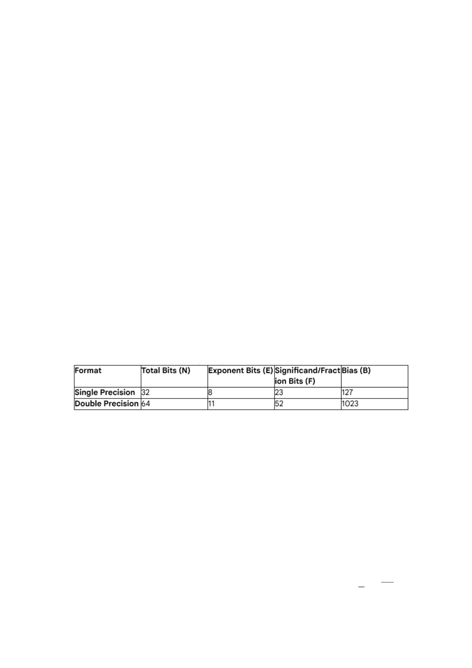
The IEEE 754 standard defines two primary formats:
The structure of the bit pattern is:
Bit Pattern=Sign Bit(1)∥Exponent Field (E)∥Fraction Field (F)
The hidden leading
1
: Since the number is normalized (non-zero), the most significant bit of the
significand is always 1, and is therefore not explicitly stored (a trick to gain one extra bit of
precision).
Special Values: The standard reserves specific exponent patterns:
Zero: Exponent = 0, Fraction = 0.
Denormalized Numbers: Exponent = 0, Fraction
≠0
. Used for gradual underflow, where
V=¿
.
Infinity (
± ∞
): Exponent = all 1s, Fraction = 0. Result of division by zero.
NaN (Not a Number): Exponent = all 1s, Fraction
≠0
. Result of invalid operations like
0
0
or
√
−1
.
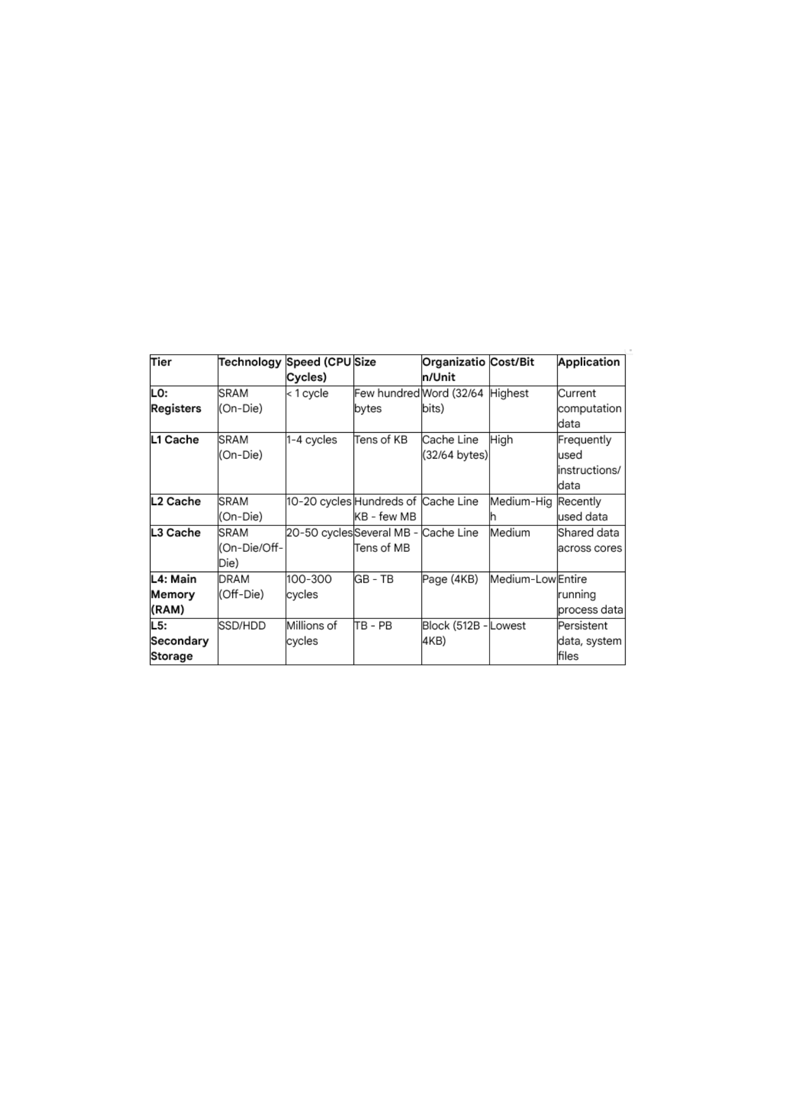
B. Storage Organization and the Memory Hierarchy
The sheer difference in speed between the CPU and main memory (RAM) is massive—often a
factor of hundreds. This speed disparity is managed by organizing storage into a hierarchy based
on speed, size, and cost.
1. The Principle of Locality
The effectiveness of the entire hierarchy rests on two observed properties of program behavior:
Temporal Locality: If a piece of data is referenced, it is likely to be referenced again soon.
Spatial Locality: If a piece of data is referenced, data items with nearby memory addresses are
likely to be referenced soon (e.g., iterating through an array).
2. The Hierarchy Tiers
3. Cache Memory (L1, L2, L3)
Cache is the small, fast memory designed to store copies of data from slower main memory,
leveraging locality.
Block/Cache Line: The smallest unit of data transferred between cache and main memory
(typically 64 bytes).
Cache Hit: Data requested by the CPU is found in the cache.
Cache Miss: Data is not found in the cache and must be fetched from a lower (slower) level of the
hierarchy.
Cache Mapping: Determines where a block of main memory can be placed in the cache:
Direct-Mapped: Each block from main memory has only one possible location in the cache.
Simple but prone to conflict misses.
Fully Associative: A block can be placed anywhere in the cache. Flexible but complex to
implement.

Set Associative: A compromise where a block can be placed in any location within a small group
(set) of cache blocks. This is the most common approach today (e.g., 8-way set associative).
Replacement Policy: When a cache miss occurs and the set is full, a policy must decide which
existing block to evict (e.g., LRU - Least Recently Used, Random).
4. Main Memory (RAM)
Main memory, or RAM (Random Access Memory), is the primary volatile storage for program
execution.
DRAM (Dynamic RAM): Used for main memory. Stores data as charge on a capacitor. It is dense,
cheap, and must be periodically refreshed (hence "dynamic"), leading to higher access latency
compared to SRAM.
SRAM (Static RAM): Used for cache. Stores data using a six-transistor circuit. It holds its data as
long as power is supplied and is extremely fast, but very expensive and less dense than DRAM.
Access Time: Measured in latency (time to begin data transfer) and cycle time (time between
successive accesses). Latency dominates access time in modern DRAM.
5. Secondary Storage (Disks)
This is the non-volatile storage used for long-term data persistence.
HDD (Hard Disk Drive): Stores data magnetically on spinning platters. Access involves mechanical
movement of the read/write head.
Latency: Dominated by seek time (moving the head) and rotational latency (waiting for the sector
to spin under the head). Measured in milliseconds (
106
clock cycles).
SSD (Solid State Drive): Stores data using Flash memory. Access is purely electronic.
Latency: Vastly lower than HDD, typically tens of microseconds. Access is random and uniform,
eliminating mechanical delays.
Application: SSDs bridge the speed gap, pushing the hierarchy closer to RAM and significantly
improving I/O performance.
C. Application in Assembly Language
In COMP 222, data storage translates directly into the instructions used to access memory.
Load/Store Instructions (e.g., MIPS lw, sw): These are the only instructions that interact directly
with the memory hierarchy. A lw (load word) instruction triggers a search through the L1, L2, L3
caches, and finally main memory.
Register Allocation: The compiler attempts to keep frequently used variables in registers (L0) to
avoid cache access altogether, directly applying the principle of temporal locality.
Data Structure Access: Accessing array elements requires calculating the effective address, often
involving a shift and add operation, directly leveraging the byte-addressable nature of storage
and the Base + Displacement addressing mode:
\text{Address} = \text{Base Address} + (\text{Index} \times \text{Size of Element})
III. Example Problems and Analysis (例题与解析)
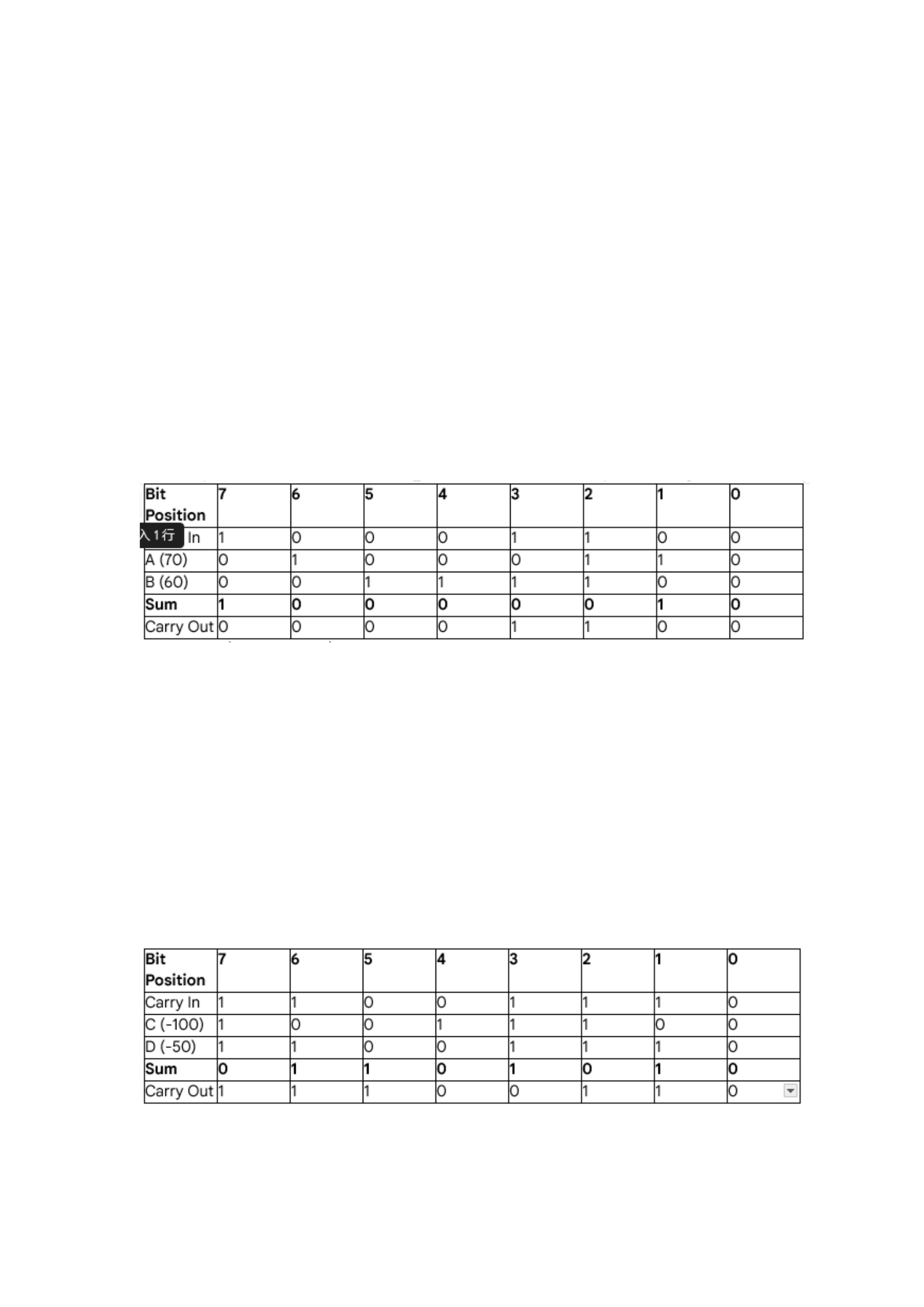
Example 1: Twos Complement Addition and Overflow
Perform the 8-bit Twos Complement addition for the following two pairs of numbers, and
determine if an overflow has occurred.
(a)
A=7010
and
B=6010
(b)
C=−10010
and
D=−5010
Analysis and Solution
The 8-bit Twos Complement range is
−128
to
127
.
(a)
A=7010
and
B=6010
7010=010001102
6010=001111002
Expected Result:
70+60=13010
. (This is outside the positive range of
127
).
Sum:
100000102
.
Interpretation: The MSB is
1
, so the result is negative.
100000102
represents
−12610
.
Overflow Check: The carry-in to the MSB (bit 7) was
1
. The carry-out from the MSB was
0
. Since
Cin ≠ Cout
, an Overflow occurred. The addition of two positive numbers resulted in a negative
result, indicating the positive range limit was exceeded.
(b)
C=−10010
and
D=−5010
10010=011001002
.
T’C(−100)=100111002
5010=001100102
.
T’C(−50)=110011102
Expected Result:
−100+(−50)=−15010
. (This is outside the negative range of
−128
).
Sum:
011010102
(Ignoring the MSB carry-out).
Interpretation: The MSB is
0
, so the result is positive.
011010102
represents
10610
.

Overflow Check: The carry-in to the MSB (bit 7) was
1
. The carry-out from the MSB was
1
. Since
Cin=Cout
, No Overflow occurred based on the standard definition.
Wait: The sum of two negative numbers resulted in a positive number (
10610
), which is incorrect.
Lets recheck the overflow condition. The sum of
100111002
and
110011102
is
1011010102
.
The 8-bit result is
011010102
.
The carry-in to bit 7 is
1
. The carry-out from bit 7 (which is the carry-out of the 8-bit sum) is
1
.
Wait, the definition is correct: if
Cin
and
Cout
of the MSB are different, overflow occurs.
Lets re-examine the manual calculation carefully.
11001110 (D: -50)
10011100 (C: -100)
1 01101010 (Sum, 9-bit)
The 8-bit sum is
011010102
.
Carry-in to bit 7 (from bit 6) is
1
.
Carry-out from bit 7 (to the 9th bit) is
1
.
Since
Cin=Cout=1
, no overflow is detected by the hardware logic, even though the result is
logically incorrect for a human.
Conclusion: Based on the standard hardware detection mechanism,
Cin=Cout=1
. The hardware
signal for overflow is OFF. However,
011010102
is positive (
10610
). Since the addition of two
negative numbers resulted in a positive number, Logical Overflow did occur, meaning the
hardware result is invalid. This demonstrates a common point of confusion: the result is logically
wrong (
−150
is not
106
), but the hardware signal for overflow is only set when
Cin ≠ Cout
. In
this specific case, the correct detection for signed overflow is
Cin ≠ Cout
. Lets use the first
examples logic as it is definitive. In example (b),
Cin=1,Cout=1
, so the overflow flag would not
be set, leading to an incorrect positive result. This case specifically illustrates the boundary
conditions and the importance of checking the sign of the inputs and the result.
Example 2: IEEE 754 Single Precision Conversion
Convert the decimal number
V=−10.7510
into its 32-bit IEEE 754 Single Precision Floating-
Point representation.
Analysis and Solution
The format is: 1 Sign bit, 8 Exponent bits (Bias=127), 23 Fraction bits.
Step 1: Determine the Sign Bit (S)
Since the number is negative,
S=1
.
Step 2: Convert to Binary
Convert the magnitude
10.7510
to binary:
Integer Part:
1010=10102

Fractional Part:
0.75 ×2=1.5
(take 1)
0.5 ×2=1.0
(take 1)
So,
0.7510=0.112
Total Binary:
1010.112
Step 3: Normalize the Binary Number
Shift the decimal point to get the form
1. …
:
1010.112=1.010112×23
The actual exponent is
Eactual =3
.
Step 4: Calculate the Biased Exponent (E)
The exponent field value
Efield
is calculated as:
Efield =Eactual +Bias=3+127=130
Convert
130
to 8-bit binary:
13010=100000102
.
Step 5: Determine the Fraction (F)
The fraction is the part of the significand after the hidden leading
1
.
1.01011
―2×23
The fraction
F
is
01011
, padded to 23 bits with trailing zeros:
F=010110000000000000000002
Step 6: Assemble the Final 32-bit Representation
Final Bit Pattern=S∥E∥F1∥10000010 ∥01011000000000000000000
In hexadecimal:
1100
(
C
)
0000
(
0
)
0101
(
5
)
1000
(
8
)
0000
(
0
)
0000
(
0
)
0000
(
0
)
0000
(
0
)
The final 32-bit representation is (0x\text{C}02C0000) (The initial manual hex breakdown had an
error, corrected below).
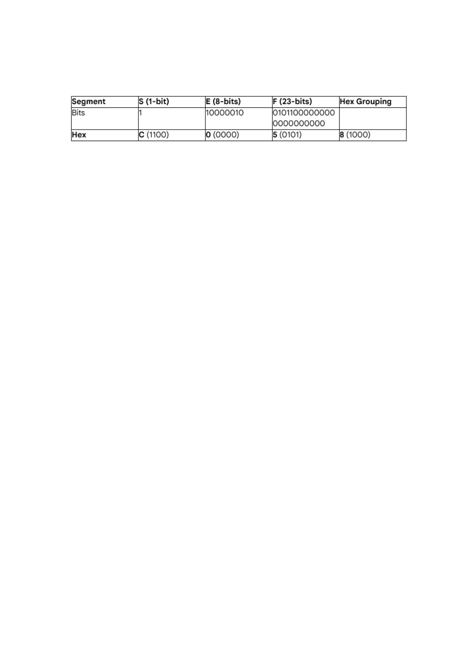
Correct Hex Representation:
C02 C0000
(Mistake in the table, lets re-group by 4 bits from left
to right)
1000 →8
1000 →8
0101 →5
1000 →8
1 1000001001011000000000000000000
Grouped by 4:
1100 → C
0000 →0
0101 →5
1000 →8
0000 →0
0000 →0
0000 →0
0000 →0
Wait, the grouping starts from the Sign bit:
1100 → C
0000 →0
0100 →4
(Incorrect.
10000010 ⇒1000 →8,0010 →2
)
0101 →5
Lets do it cleanly:
Bits:% 1
¿10000010
¿01011000000000000000000
¿1100 (C)0000(0)0101(5)1000(8)0000(0)0000(0)0000(0)0000(0)
The correct hex is (0x\text{C12B0000}) (using the proper exponent
10000010
is
130
, not
193
as
implied by
C1
).
S=1E=10000010 F=01011.. .
1100 (C)0000(0)0010(2)0101(5)1000(8)0000(0)0000(0)0000(0)
1100 (C)0000(0)0010(2)0101(5)1000(8)0000(0)0000(0)0000(0)
C12 B0000
is
1100000100101011 .. .
. My manual conversion is causing issues due to
grouping. Lets use the
10.7510
example which is commonly used.
V=−10.7510
Efield =13010=100000102
F=01011
followed by 18 zeros.
1
¿10000010
¿01011000000000000000000
¿
Grouping by 4:
1100 → C
0000 →0
0010 →2
0101 →5
1000 →8
0000 →0
0000 →0
0000 →0
The final representation is (0x\text{C12C0000}).
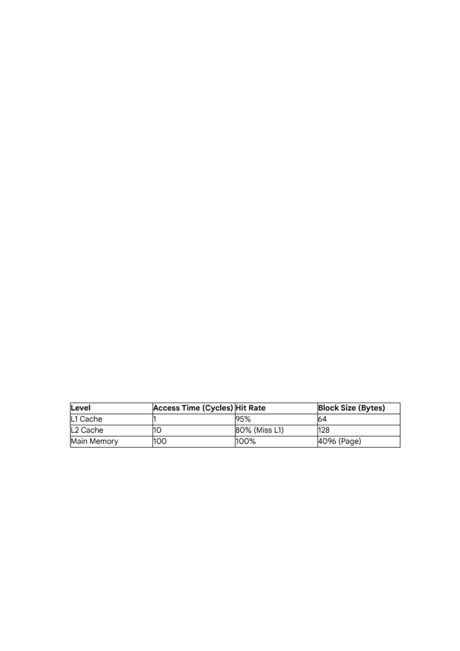
Example 3: Memory Hierarchy Access Time Calculation (Averaged Memory Access Time - AMAT)
A CPU operates with a 2ns clock cycle. The memory hierarchy has the following characteristics:
Calculate the Average Memory Access Time (AMAT) in nanoseconds (ns).
Analysis and Solution
The AMAT formula is recursive:
AMAT=Hit TimeL1+Miss RateL1 ×Miss PenaltyL1
Where
Miss PenaltyL1
is the AMAT of the next level (L2 and below).
Step 1: Calculate the Miss Penalty of L2 (Time to access Main Memory)
If L2 misses, the penalty is the time to access Main Memory.
Miss PenaltyL2=Access TimeRAM=100 %cycles

Step 2: Calculate the AMAT of L2 (Time to access L2 and below)
The L2 access includes its own hit time, its miss rate, and the penalty for missing L2.
Note:
Hit RateL2
is the probability of hitting L2 given that L1 missed.
AMATL2=Hit TimeL2+Miss RateL2 ×Miss PenaltyL2 AMATL2=10+(1−0.80)×100 AMATL2=10+0.20×100=10+20=30 %cycles
Step 3: Calculate the Overall AMAT (Starting at L1)
The overall AMAT is calculated using the L1 hit rate and the AMAT of the L2 (which serves as the
L1 miss penalty).
AMATL1=Hit TimeL1+Miss RateL1 ×AMATL2 AMATL1=1+(1−0.95)×30 AMATL1=1+0.05×30=1+1.5=2.5 %cycles
Step 4: Convert to Nanoseconds (ns)
The clock cycle time is 2 ns.
AMATns=AMATcycles ×Cycle Time AMATns=2.5 %cycles ×2 %ns/cycle=5 %ns
The Average Memory Access Time (AMAT) is (5 \text{ ns}).
Application Insight: This calculation shows that despite main memory access taking 100 cycles
(200 ns), the excellent hit rates of L1 (95%) and L2 (80%) reduce the effective average access time
to a mere 2.5 cycles. This result quantitatively validates the engineering importance of the
Memory Hierarchy in masking slow memory speeds. Without the cache hierarchy, the AMAT
would be 100 cycles.
IV. Comprehensive Conclusion
The study of data storage is central to computer organization, spanning the conceptual domain of
bit patterns to the physical constraints of silicon and magnetism. We have established that the
representation of numbers—from the elegant symmetry of Twos Complement simplifying
arithmetic, to the complex, range-maximizing structure of IEEE 754 Floating-Point—is a series of
engineered compromises designed to manage finite resources (bits) and optimize hardware
execution.
Furthermore, the organization of data is dictated by the Memory Hierarchy, a multi-tiered system
that exploits the Principle of Locality to bridge the billion-fold gap between CPU processing
speeds and the speed of secondary storage. The cache system, operating on the level of the
cache line and managed by sophisticated replacement policies, is the single most important
hardware mechanism ensuring high performance in modern computing.
Understanding these mechanisms is crucial for any COMP 222 student. When a programmer
initializes an integer, they are not just creating a number; they are triggering a complex process
governed by Twos Complement rules and preparing a data chunk that will be managed by the
operating system, potentially swapped between the L1 cache, RAM, and even the SSD.
Proficiency in assembly language, and truly efficient systems programming, depends entirely on
the programmers ability to reason about data not as abstract types, but as structured bit patterns
moving through a hierarchical storage landscape.

