



RELIABILITY, AVAILABILITY, AND SERVICEABILITY (RAS)
Dealing with Uncorrectable Errors
The main memory of a server is protected using error correcting codes (ECC ). This is a
common hardware feature that can automatically correct many memory errors that
happen due to transient hardware issues, such as power spikes, soft media errors, and
so on. If an error is severe enough, it will corrupt enough bits that ECC cannot correct;
the result is called an uncorrectable error (UE).
Uncorrectable errors in persistent memory require special RAS handling that differs
from how a platform may traditionally handle volatile memory uncorrectable errors.
Persistent memory uncorrectable errors are persistent. Unlike volatile memory, if
power is lost or an application crashes and restarts, the uncorrectable error will remain
on the hardware. This can lead to an application getting stuck in an infinite loop such as
1.
Application starts
2. Reads a memory address
3. Encounters uncorrectable error
4. Crashes (or system crashes and reboots)
5. Starts and resumes operation from where it left off
6. Performs a read on the same memory address that triggered the previous
restart
7. Crashes (or system crashes and reboots)
8. …
9. Repeats infinitely until manual intervention
The operating system and applications may need to address uncorrectable errors in
three main ways:
When consuming previously undetected uncorrectable errors during
runtime
When unconsumed uncorrectable errors are detected at runtime
When mitigating uncorrectable memory locations detected at boot
Consumed Uncorrectable Error Handling
When an uncorrectable error is detected on a requested memory address, data
poisoning is used to inform the CPU that the data requested has an uncorrectable error.
When the hardware detects an uncorrectable memory error, it routes a poison bit along

with the data to the CPU. For the Intel architecture, when the CPU detects this poison
bit, it sends a processor interrupt signal to the operating system to notify it of this error.
This signal is called a machine check exception (MCE) . The operating system can then
examine the uncorrectable memory error, determine if the software can recover, and
perform recovery actions via an MCE handler. Typically, uncorrectable errors fall into
three categories:
Uncorrectable errors that may have corrupted the state of the CPU and
require a system reset.
Uncorrectable errors that can be recovered by software can be handled
during runtime.
Uncorrectable errors that require no action.
Operating system vendors handle this uncorrectable error notification in different
ways, but some common elements exist for all of them.
Using Linux as an example, when the operating system receives a processor
interrupt for an uncorrectable error, it proceeds to offline the page of memory where
the uncorrectable error occurred and add the error to a list of areas containing known
uncorrectable errors. This list of known uncorrectable errors is called the bad block list.
Linux will also mark the page that contains the uncorrectable error to be cleared when
the page is recycled for use by another application.
The PMDK libraries automatically check the list of pages with uncorrectable errors
in the operating system and prevent an application from opening a persistent memory
pool if it contains errors. If a page of memory is in use by an application, Linux attempts
to kill it using the SIGBUS mechanism.
At this point, the application developer can decide what to do with this error
notification. The simplest way for you to handle uncorrectable errors is to let the
application die when it gets a SIGBUS so you do not need to write the complicated logic
of handling a SIGBUS at runtime. Instead, on restart, the application can use PMDK to
detect that the persistent memory pool contains errors and repair the data during
application initialization. For many applications, this repair can be as simple as
reverting to a backup error-free copy of the data.
Figure 17-1 shows a simplified sequence of how Linux can handle an uncorrectable
(but not fatal) error that was consumed by an application.
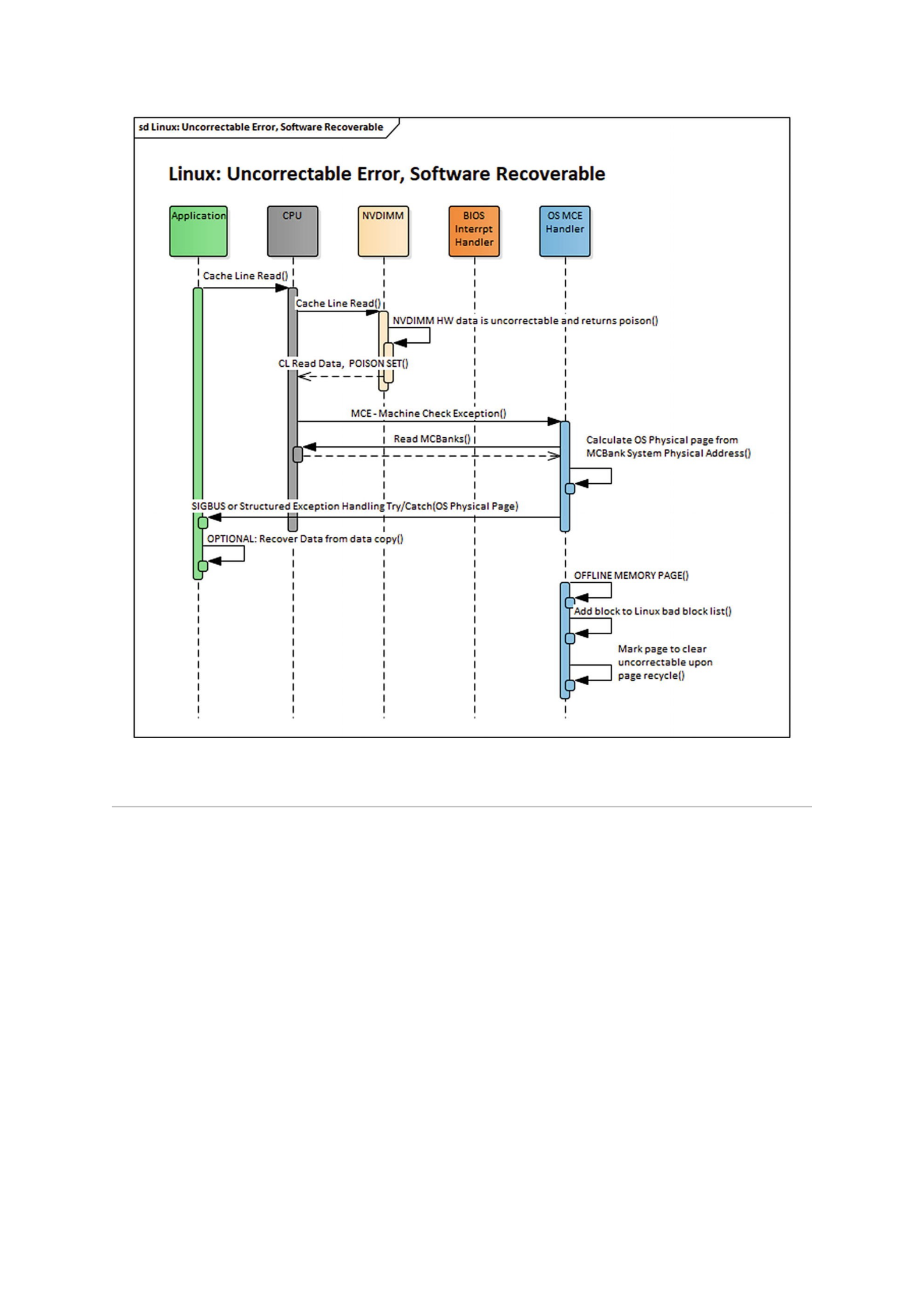
Figure 17-1Linux consumed uncorrectable error-handling sequence
Unconsumed Uncorrectable Error Handling
RAS features are defined to inform software of uncorrectable errors that have been
discovered on the persistent memory media but have not yet been consumed by
software. The goal of this feature is to allow the operating system to opportunistically
offline or clear pages with known uncorrectable errors before they can be used by an
application. If the address of the uncorrectable error is already in use by an application,
the operating system may also choose to notify it of the unconsumed uncorrectable
error or wait until the application consumes the error. The operating system may
choose to wait on the chance that the application never tries to access the affected page
and later return the page to the operating system for recycling. At this time, the
operating system would clear or offline the uncorrectable error.
Unconsumed uncorrectable error handling may be implemented differently on
different vendor platforms, but at the core, there will always be a mechanism to
discover the unconsumed uncorrectable error, a mechanism to signal the operating
system of an unconsumed uncorrectable error, and a mechanism for the operating
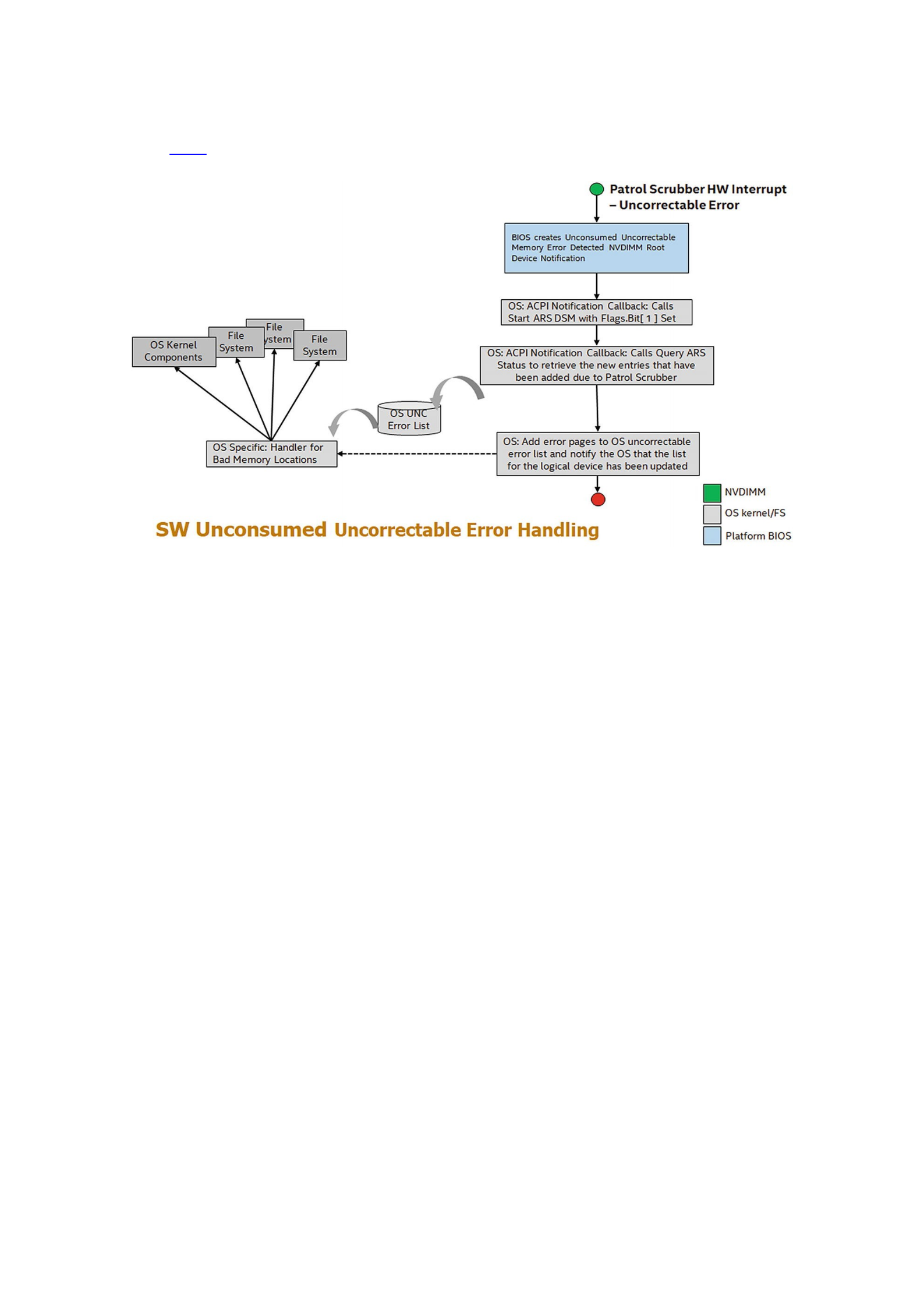
system to query information about the unconsumed uncorrectable error. As shown in
Figure 17-2, these three mechanisms work together to proactively keep the operating
system informed of all discovered uncorrectable errors during runtime.
Figure 17-2Unconsumed uncorrectable error handling
Patrol Scrub
Patrol scrub (also known as memory scrubbing) is a long-standing RAS feature for
volatile memory that can also be extended to persistent memory. It is an excellent
example of how a platform can discover uncorrectable errors in the background during
normal operation.
Patrol scrubbing is done using a hardware engine, on either the platform or on the
memory device, which generates requests to memory addresses on the memory device.
The engine generates memory requests at a predefined frequency. Given enough time, it
will eventually access every memory address. The frequency in which patrol scrub
generates requests produces no noticeable impact on the memory device’s quality of
service.
By generating read requests to memory addresses, the patrol scrubber allows the
hardware an opportunity to run ECC on a memory address and correct any correctable
errors before they can become uncorrectable errors. Optionally, if an uncorrectable
error is discovered, the patrol scrubber can trigger a hardware interrupt and notify the
software layer of its memory address.
Unconsumed Uncorrectable Memory-Error Persistent Memory Root-Device
Notification
The ACPI specification describes a method for hardware to notify software of
unconsumed uncorrectable errors called the Unconsumed Uncorrectable Memory-Error
Persistent Memory Root-Device Notification. Using the ACPI-defined framework, the
operating system can subscribe to be notified by the platform whenever an
uncorrectable memory error is detected. It is the platform’s responsibility to receive

notification from persistent memory devices that an uncorrectable error has been
detected and take appropriate action to generate a persistent memory root-device
notification. Upon receipt of root-device notification, the operating system can then use
existing ACPI methods, such as Address Range Scrub (ARS), to discover the address of
the newly created uncorrectable memory error and take appropriate actions.
Address Range Scrub
ARS is a device-specific method (_DSM) defined in the ACPI specification. Privileged
software can call an ACPI _DSM such as ARS at runtime to retrieve or scan for the
locations of uncorrectable memory errors for all persistent memory in the platform.
Because ARS is implemented by the platform, each vendor may implement some of the
functionality differently.
An ARS accepts a given system address range from the caller and, like patrol scrub,
inspects each memory address in that range for memory errors. When ARS completes,
the caller is given a list of memory addresses in the given range that contains memory
errors. Inspection of each memory address may be handled by persistent memory
hardware or by the platform itself. Unlike a patrol scrub, ARS inspects each memory
address at a very high frequency. This increased frequency of the scrub may impact the
quality of service for the persistent memory hardware. Thus, ARS can optionally be
invoked by the caller to return the results of the previous ARS, sometimes referred to as
a short ARS.
Traditionally, the operating system executes ARS in one of two ways to obtain the
addresses of uncorrectable errors after a boot. Either a full scan is executed on all the
available persistent memory during system boot or after an unconsumed uncorrectable
memory error root-device notification is received. In both instances, the intent is to
discover these addresses before they are consumed by applications.
Operating systems will compare the list of uncorrectable errors returned by ARS to
their persistent list of uncorrectable errors. If new errors are detected, the list is
updated. This list is intended to be consumed by higher-level software, such as the
PMDK libraries.
Clearing Uncorrectable Errors
Uncorrectable errors for persistent memory will survive power loss and may require
special handling to clear corrupted data from the memory address. When an
uncorrectable error is cleared, the data at the requested memory address is modified,
and the error is cleared. Because hardware cannot silently modify application data,
clearing uncorrectable errors is the software’s responsibility. Clearing uncorrectable
errors is optional, and some operating systems may choose to only offline memory
pages that contain memory errors instead of recycling memory pages that contain
uncorrectable errors. In some operating systems, privileged applications may have
access to clear uncorrectable errors. Nevertheless, an operating system is not required
to provide this access.
The ACPI specification defines a Clear Uncorrectable Error DSM for operating
systems to instruct the platform to clear the uncorrectable errors. While persistent
memory programming is byte addressable, clearing uncorrectable errors is not.

Different vendor implementations of persistent memory may specify the alignment and
size of the memory unit that is to be cleared by a Clear Uncorrectable Error. Any
internal platform or operating system list of memory errors should also be updated
upon successful executing of the Clear Uncorrectable Error DSM command.
Device Health
System administrators may wish to act and mitigate any device health issues before
they begin to affect the availability of applications using persistent memory. To that end,
operating systems or management applications will want to discover an accurate
picture of persistent memory device health to correctly determine the reliability of the
persistent memory. The ACPI specification defines a few vendor-agnostic health
discovery methods, but many vendors choose to implement additional persistent
memory device methods for attributes that are not covered by the vendor-agnostic
methods. Many of these vendor-specific health discovery methods are implemented as
an ACPI device-specific method (_DSM). Applications should be aware of degradation to
the quality of service if they call ACPI methods directly, since some platform
implementations may impact memory traffic when ACPI methods are invoked. Avoid
excessive polling of device health methods when possible.
On Linux, the ndctl utility can be used to query the device health of persistent
memory modules. Listing 17-1 shows an example output of an Intel Optane DC
persistent memory module.
$ sudo ndctl list -DH -d nmem1
[
{
"dev":"nmem1",
"id":"8089-a2-1837-00000bb3",
"handle":17,
"phys_id":44,
"security":"disabled",
"health":{
"health_state":"ok",
"temperature_celsius":30.0,
"controller_temperature_celsius":30.0,
"spares_percentage":100,
"alarm_temperature":false,
"alarm_controller_temperature":false,
"alarm_spares":false,
"alarm_enabled_media_temperature":false,
"alarm_enabled_ctrl_temperature":false,
"alarm_enabled_spares":false,
"shutdown_state":"clean",
"shutdown_count":1
}
}
]
Listing 17-1Using ndctl to query the health of persistent memory modules

Conveniently, ndctl also provides a monitoring command and daemon to
continually monitor the health of the systems’ persistent memory modules. For a list of
all the available options, refer to the ndctl-monitor(1) man page. Examples for
using this monitor method include
Example 1: Run a monitor as a daemon to monitor DIMMs on bus “nfit_test.1,”
$ sudo ndctl monitor --bus=nfit_test.1 --daemon
Example 2: Run a monitor as a one-shot command, and output the notifications to
/var/log/ndctl.log.
$ sudo ndctl monitor --log=/var/log/ndctl.log
Example 3: Run a monitor daemon as a system service.
$ sudo systemctl start ndctl-monitor.service
You can obtain similar information using the persistent memory device-specific
utility. For example, you can use the ipmctl utility on Linux and Windows to obtain∗
hardware-level data similar to that shown by ndctl. Listing 17-2 shows health
information for DIMMID 0x0001 (nmem1 equivalent in ndctl terms).
$ sudo ipmctl show -sensor -dimm 0x0001
DimmID | Type | CurrentValue
=====================================================
0x0001 | Health | Healthy
0x0001 | MediaTemperature | 30C
0x0001 | ControllerTemperature | 31C
0x0001 | PercentageRemaining | 100%
0x0001 | LatchedDirtyShutdownCount | 1
0x0001 | PowerOnTime | 27311231s
0x0001 | UpTime | 6231933s
0x0001 | PowerCycles | 170
0x0001 | FwErrorCount | 8
0x0001 | UnlatchedDirtyShutdownCount | 107
Listing 17-2Health information for DIMMID 0x0001
ACPI-Defined Health Functions (_NCH, _NBS)
The ACPI specification includes two vendor-agnostic methods for operating systems
and management software to call for determining the health of a persistent memory
device.
Get NVDIMM Current Health Information (_NCH) can be called by the operating
systems at boot time to get the current health of the persistent memory device and take
appropriate action. The values reported by _NCH can change during runtime and should
be monitored for changes. _NCH contains health information that shows if
The persistent memory requires maintenance
The persistent memory device performance is degraded
The operating system can assume write persistency loss on subsequent
power events
The operating system can assume all data will be lost on subsequent power
events
Get NVDIMM Boot Status (_NBS) allows operating systems a vendor-agnostic
method to discover persistent memory health status that does not change during

runtime. The most significant attribute reported by _NBS is Data Loss Count (DLC). Data
Loss Count is expected to be used by applications and operating systems to help identify
the rare case where a persistent memory dirty shutdown has occurred. See
“Unsafe/Dirty Shutdown” later in this chapter for more information on how to properly
use this attribute.
Vendor-Specific Device Health (_DSMs)
Many vendors may want to add further health attributes beyond what exists in _NBS
and _NCH. Vendors are free to design their own ACPI persistent memory device-specific
methods (_DSM) to be called by the operating system and privileged applications.
Although vendors implement persistent memory health discovery differently, a few
common health attributes are likely to exist to determine if a persistent memory device
requires service. These health attributes may include information such as an overall
health summary of the persistent memory, current persistent memory temperature,
persistent media error counts, and total device lifetime utilization. Many operating
systems, such as Linux, include support to retrieve and report the vendor-unique health
statistics through tools such as ndctl. The Intel persistent memory _DSM interface
document can be found under the “Related Specification” section of
https://docs.pmem.io/.
ACPI NFIT Health Event Notification
Due to the potential loss of quality of service, operating systems and privileged
applications may not want to actively poll persistent memory devices to retrieve device
health. Thus, the ACPI specification has defined a passive notification method to allow
the persistent memory device to notify when a significant change in device health has
occurred. Persistent memory device vendors and platform BIOS vendors decide which
device health changes are significant enough to trigger an NVDIMM Firmware Interface
Table (NFIT) health event notification. Upon receipt of an NFIT health event, a
notification to the operating system is expected to call an _NCH or a _DSM attached to
the persistent memory device and take appropriate action based on the data returned.
Unsafe/Dirty Shutdown
An unsafe or dirty shutdown on persistent memory means that the persistent memory
device power-down sequence or platform power-down sequence may have failed to
write all in-flight data from the system’s persistence domain to persistent media.
(Chapter 2 describes persistence domains.) A dirty shutdown is expected to be a very
rare event, but they can happen due to a variety of reasons such as physical hardware
issues, power spikes, thermal events, and so on.
A persistent memory device does not know if any application data was lost as a
result of the incomplete power-down sequence. It can only detect if a series of events
occurred in which data may have been lost. In the best-case scenario, there might not
have been any applications that were in the process of writing data when the dirty
shutdown occurred.

The RAS mechanism described here requires the platform BIOS and persistent
memory vendor to maintain a persistent rolling counter that is incremented anytime a
dirty shutdown is detected. The ACPI specification refers to such a mechanism as the
Data Loss Count (DLC) that can be returned as part of the Get NVDIMM Boot
Status(_NBS) persistent memory device method.
Referring to the output from ndctl in Listing 17-1, the "shutdown_count" is
reported in the health information. Similarly, the output from ipmctl in Listing 17-2
reports "LatchedDirtyShutdownCount" as the dirty shutdown counter. For both
outputs, a value of 1 means no issues were detected.
Application Utilization of Data Loss Count (DLC)
Applications may want to use the DLC counter provided by _NBS to detect if possible
data loss occurred while saving data from the system’s persistence domain to the
persistent media. If such a loss can be detected, applications can perform data recovery
or rollback using application-specific features.
The application’s responsibilities and possible implementation suggestions for
applications are outlined as follows:
1.
Application first creates its initial metadata and stores it in a persistent memory file:
a.
Application retrieves current DLC via operating system–specific means for the
physical persistent memory that make up the logical volume the applications
metadata resides on.
b. Application calculates the current Logical Data Loss Count (LDLC) as the sum of
the DLC for all physical persistent memory that make up the logical volume the
applications metadata resides on.
c. Application stores the current LDLC in its metadata file and ensures that the
update of the LDLC has been flushed to the system’s persistence domain. This is
done by using a flush that forces the write data all the way to the persistent
memory power-fail safe domain. (Chapter 2 contains more information about
flushing data to the persistence domain.)
d. Application determines GUID or UUID for the logical volume the applications
metadata resides on, stores this in its metadata file, and ensures the update of the
GUID/UUID to the persistence domain. This is used by the application to later
identify if the metadata file has been moved to another logical volume, where the
current DLC is no longer valid.
e. Application creates and sets a “clean” flag in its metadata file and ensures the
update of the clean flag to the persistence domain. This is used by the application
to determine if the application was actively writing data to persistence during
dirty shutdown.
2. Every time the application runs and retrieves its metadata from persistent memory:
a.
Application checks the GUID/UUID saved in its metadata with the current UUID
for the logical volume the applications metadata resides on. If they match, then the
LDLC is describing the same logical volume the app was using. If they do not
match, then the DLC is for some other logical volume and no longer applies. The
application decides how to handle this.

b. Application calculates the current LDLC as the sum of the DLC for all physical
persistent memory the application’s metadata resides on.
c. Application compares the current LDLC calculated with the saved LDLC retrieved
from its metadata.
d. If the current LDLC does not match the saved LDLC, then one or more persistent
memory have detected a dirty shutdown and possible data loss. If they do match,
no further action is required by the application.
e. Application checks the status of the saved “clean” flag in its metadata; if the clean
flag is NOT set, this application was writing at the time of the shutdown failure.
f. If the clean flag is NOT set, perform software data recovery or rollback using
application-specific functionality.
g. Application stores the new current LDLC in its metadata file and ensures that the
update of the count has been flushed to the system’s persistence domain. This may
require unsetting the clean flag if it was previously set.
h. Application sets the clean flag in its metadata file and ensures that the update of
the clean flag has been flushed to the persistence domain.
3. Every time the application will write to the file:
a.
Before the application writes data, it clears the “clean” flag in its metadata file and
ensures that the flag has been flushed to the persistence domain.
b. Application writes data to its persistent memory space.
c. After the application completes writing data, it sets the “clean” flag in its metadata
file and ensures the flag has been flushed to the persistence domain.
PMDK libraries make these steps significantly easier and account for interleaving set
configurations.
Having remote direct memory access via a high-performance network connection is
a critical use case for most cloud deployments of persistent memory. Typically, in high-
availability or highly redundant use cases, data written locally to persistent memory is
not considered reliable until it has been replicated to two or more remote persistent
memory devices on separate remote servers. We describe this push model design later
in this chapter.
While it is certainly possible to use existing TCP/IP networking infrastructures to
remotely access the persistent memory, this chapter focuses on the use of remote direct
memory access (RDMA). Direct memory access (DMA) allows data movement on a
platform to be off-loaded to a hardware DMA engine that moves that data on behalf of
the CPU, freeing it to do other important tasks during the data move. RDMA applies the
same concept and enables data movement between remote servers to occur without the
CPU on either server having to be directly involved.
This chapter’s content and the PMDK librpmem remote persistent memory library
that is discussed assume the use of RDMA, but the concepts discussed here can apply to
other networking interconnects and protocols.
Figure 18-1 outlines a simple remote persistent memory configuration with one
initiator system that is replicating writes to persistent memory on a single remote
target system. While this shows the use of persistent memory on both the initiator and
target, it is possible to read data from initiator DRAM and write to persistent memory
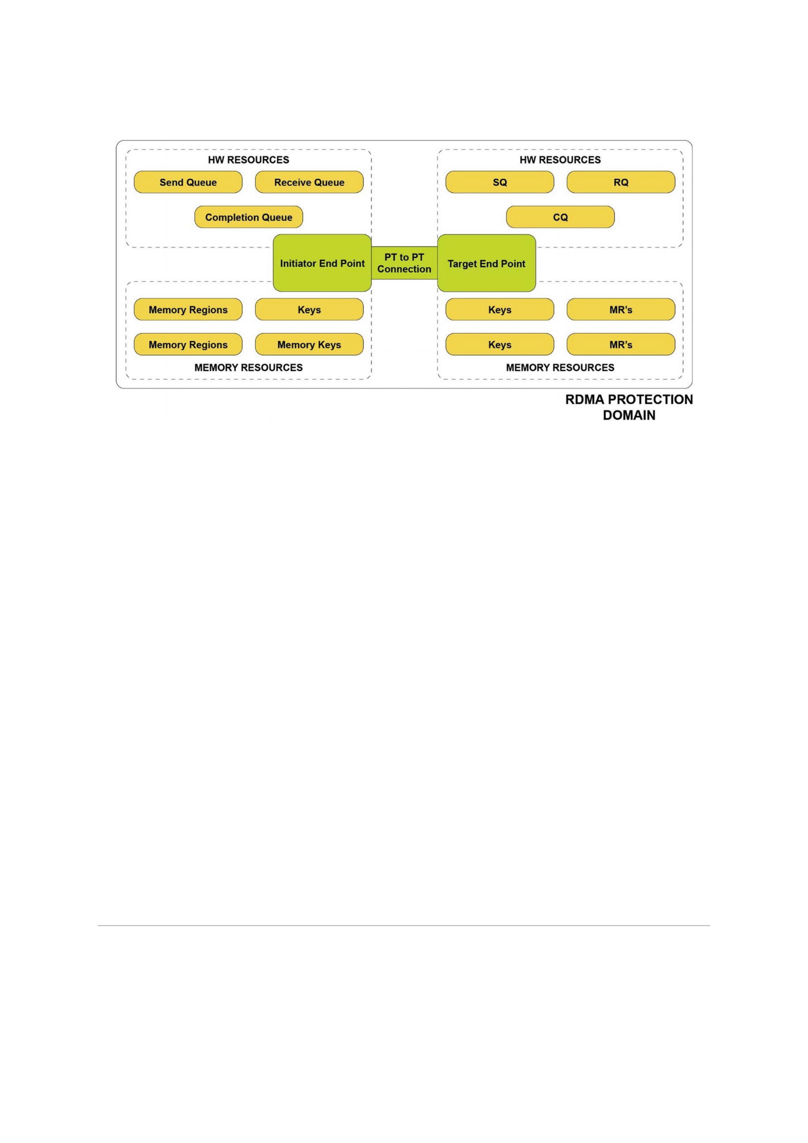
on the remote target system, or read from the initiator’s persistent memory and write
to the remote target’s DRAM.
Figure 18-1Initiator and target system using RDMA
ACPI-Defined Health Functions (_NCH, _NBS)
The ACPI specification includes two vendor-agnostic methods for operating systems
and management software to call for determining the health of a persistent memory
device.
Get NVDIMM Current Health Information (_NCH) can be called by the operating
systems at boot time to get the current health of the persistent memory device and take
appropriate action. The values reported by _NCH can change during runtime and should
be monitored for changes. _NCH contains health information that shows if
The persistent memory requires maintenance
The persistent memory device performance is degraded
The operating system can assume write persistency loss on subsequent
power events
The operating system can assume all data will be lost on subsequent power
events
Get NVDIMM Boot Status (_NBS) allows operating systems a vendor-agnostic
method to discover persistent memory health status that does not change during
runtime. The most significant attribute reported by _NBS is Data Loss Count (DLC). Data
Loss Count is expected to be used by applications and operating systems to help identify
the rare case where a persistent memory dirty shutdown has occurred. See
“Unsafe/Dirty Shutdown” later in this chapter for more information on how to properly
use this attribute.
Vendor-Specific Device Health (_DSMs)
Many vendors may want to add further health attributes beyond what exists in _NBS
and _NCH. Vendors are free to design their own ACPI persistent memory device-specific
methods (_DSM) to be called by the operating system and privileged applications.

Although vendors implement persistent memory health discovery differently, a few
common health attributes are likely to exist to determine if a persistent memory device
requires service. These health attributes may include information such as an overall
health summary of the persistent memory, current persistent memory temperature,
persistent media error counts, and total device lifetime utilization. Many operating
systems, such as Linux, include support to retrieve and report the vendor-unique health
statistics through tools such as ndctl. The Intel persistent memory _DSM interface
document can be found under the “Related Specification” section of
https://docs.pmem.io/.
ACPI NFIT Health Event Notification
Due to the potential loss of quality of service, operating systems and privileged
applications may not want to actively poll persistent memory devices to retrieve device
health. Thus, the ACPI specification has defined a passive notification method to allow
the persistent memory device to notify when a significant change in device health has
occurred. Persistent memory device vendors and platform BIOS vendors decide which
device health changes are significant enough to trigger an NVDIMM Firmware Interface
Table (NFIT) health event notification. Upon receipt of an NFIT health event, a
notification to the operating system is expected to call an _NCH or a _DSM attached to
the persistent memory device and take appropriate action based on the data returned.
Unsafe/Dirty Shutdown
An unsafe or dirty shutdown on persistent memory means that the persistent memory
device power-down sequence or platform power-down sequence may have failed to
write all in-flight data from the system’s persistence domain to persistent media.
(Chapter 2 describes persistence domains.) A dirty shutdown is expected to be a very
rare event, but they can happen due to a variety of reasons such as physical hardware
issues, power spikes, thermal events, and so on.
A persistent memory device does not know if any application data was lost as a
result of the incomplete power-down sequence. It can only detect if a series of events
occurred in which data may have been lost. In the best-case scenario, there might not
have been any applications that were in the process of writing data when the dirty
shutdown occurred.
RDMA Networking Protocols
Examples of popular RDMA networking protocols used throughout the cloud and
enterprise data centers include:
InfiniBand is an I/O architecture and high-performance specification for data
transmission between high-speed, low-latency, and highly scalable CPUs,
processors, and storage.
RoCE (RDMA over Converged Ethernet) is a network protocol that allows
RDMA over an Ethernet network.

iWARP (Internet Wide Area RDMA Protocol) is a networking protocol that
implements RDMA for efficient data transfer over Internet Protocol
networks.
All three protocols support high-performance data movement to and from persistent
memory using RDMA.
The RDMA protocols are governed by the RDMA Wire Protocol Standards, which are
driven by the IBTA (InfiniBand Trade Association) and the IEFT (Internet Engineering
Task Force) specifications. The IBTA (https://www.infinibandta.org/) governs
the InfiniBand and RoCE protocols, while the IEFT (https://www.ietf.org/)
governs iWARP.
Low-latency RDMA networking protocols allow the network interface controller
(NIC) to control the movement of data between an initiator node source buffer and the
sink buffer on the target node without needing either node’s CPU to be involved in the
data movement. In fact, RDMA Read and RDMA Write operations are often referred to as
one-sided operations because all of the information required to move the data is
supplied by the initiator and the CPU on the target node is not typically interrupted or
even aware of the data transfer.
To perform remote data transfers, information from the target node’s buffers must
be passed to the initiator before the remote operation( s) will begin. This requires
configuring the local initiator’s RDMA resources and buffers. Similarly, the remote
target node’s RDMA resources that will require CPU resources will need to be initialized
and reported to the initiator. However, once the resources for the RDMA transfers are
set up and applications initiate the RDMA request using the CPU, the NIC does the actual
data movement on behalf of the RDMA-aware application.
RDMA-aware applications are responsible for:
Interrogating each NIC on every initiator and target system to determine
supported features
Selecting a NIC for each end of the RDMA point-to-point connection
Creating the connection with the selected NICs, described as an RDMA
protection domain
Allocating queues for the incoming and outgoing message on each NIC and
assigning those hardware resources to the protection domain
Allocating DRAM or persistent memory buffers for use with RDMA,
registering those buffers with the NIC, and assigning those buffers to the
protection domain
Three basic RDMA commands are used by most RDMA-capable applications and
libraries:
RDMA Write: A one-sided operation where only the initiator supplies all of the
information required for the transfer to occur. This transfer is used to write data to the
remote target node. The write request contains all source and sink buffer information.
The remote target system is not typically interrupted and thus completely unaware of
the write operations occurring through the NIC. When the initiator’s NIC sends a write
to the target, it will generate a “software write completion interrupt.” A software write
completion interrupt means that the write message has been sent to the target NIC and
is not an indicator of the write completion. Optionally, RDMA Writes can use an
immediate option that will interrupt the target node CPU and allow software running
there to be immediately notified of the write completion.

RDMA Read: A one-sided operation where only the initiator supplies all of the
information required for the transfer to occur. This transfer is used to read data from
the remote target node. The read request contains all source buffer and target sink
buffer information, and the remote target system is not typically interrupted and thus
completely unaware of the read operations occurring through the NIC. The initiator
software read completion interrupt is an acknowledgment that the read has traversed all
the way through the initiator’s NIC, over the network, into the target system’s NIC,
through the target internal hardware mesh and memory controllers, to the DRAM or
persistent memory to retrieve the data. Then it returns all the way back to the initiator
software that registered for the completion notification.
RDMA Send (and Receive): The two-sided RDMA Send means that both the
initiator and target must supply information for the transfer to complete. This is
because the target NIC will be interrupted when the RDMA Send is received by the
target NIC and requires a hardware receive queue to be set up and pre-populated with
completion entries before the NIC will receive an RDMA Send transfer operation. Data
from the initiator application is bundled in a small, limited sized buffer and sent to the
target NIC. The target CPU will be interrupted to handle the send operation and any
data it contains. If the initiator needs to be notified of receipt of the RDMA Send, or to
handle a message back to the initiator, another RDMA Send operation must be sent in
the reverse direction after the initiator has set up its own receive queue and queued
completion entries to it. The use of the RDMA Send command and the contents of the
payload are application-specific implementation details. An RDMA Send is typically used
for bookkeeping and updates of read and write activity between the initiator and the
target, since the target application has no other context of what data movement has
taken place. For example, because there is no good way to know when writes have
completed on the target, an RDMA Send is often used to notify the target node what is
happening. For small amounts of data, the RDMA Send is very efficient, but it always
requires target-side interaction to complete. An RDMA Write with immediate data
operation will also allow the target node to be interrupted when the write has
completed as a different mechanism for bookkeeping.
Goals of the Initial Remote Persistent Memory
Architecture
The goal of the first remote persistent memory implementation was based on
minimal changes – or ideally, no changes – to the current RDMA hardware and software
stacks used with volatile memory. From a network hardware, middleware, and software
architecture standpoint, writing to remote volatile memory is identical to writing to
remote persistent memory. The knowledge that a specific memory-mapped file is
backed by persistent memory vs. volatile memory is entirely the responsibility of the
application to maintain. None of the lower layers in the networking stack are aware of
the fact that the write is to a persistent memory region or volatile memory. The
responsibility of knowing which write persistence method to use for a given target
connection, and making those remote writes persistent, falls to the application.
Guaranteeing Remote Persistence

Until this chapter, much of the book focuses on the use and programming of
persistent memory on the local machine. You are now aware of some of the challenges
of using persistent memory, the persistence domain, and the need to understand and
use a flushing mechanism to ensure the data is persistent. These same programming
concepts and challenges apply to remote persistent memory with the additional
constraints of making it work within the existing network protocol and network latency.
The SNIA NVM programming model (described in Chapter 3) requires applications
to flush data that has been written to persistent memory to guarantee that the written
data made it into the persistence domain. This same requirement applies to writing to
remote persistent memory. After the RDMA Write or Send operation has moved the
data from the initiator node to the persistent memory on the target node, that write or
send data needs to be flushed to the persistence domain on the remote system.
Alternatively, the remote write or send data needs to bypass CPU caches on the remote
node to avoid having to be flushed.
Different vendor-specific platform features add an extra challenge to RDMA and to
remote persistent memory. Intel platforms typically use a feature called allocating
writes or Direct Data IO (DDIO) which allows incoming writes to be placed directly into
the CPU’s L3 cache. The data is immediately visible to any application wanting to read
the data. However, having allocating writes enabled means that RDMA Writes to
persistent memory now have to be flushed to the persistence domain on the target
node.
On Intel platforms, allocating writes can be disabled by turning on non-allocating
write I/O flows which forces the write data to bypass cache and be placed directly into
the persistent memory, governed by the location of the RDMA Write sink buffer. This
would slow down applications that will immediately touch the newly written data
because they incur the penalty to pull the data into CPU cache. However, this simplifies
making remote writes to persistent memory simpler and faster because cache flushing
on the remote target node can be avoided. An additional complication to using non-
allocating write mode on an Intel platform is that an entire PCI root complex must be
enabled for this write mode. This means that any inbound writes that come through that
PCI root complex, for any device connected downstream of it, will have write-data
bypass CPU caches, causing possible additional performance latency as a side effect.
Intel specifies two methods for forcing writes to remote persistent memory into the
persistence domain:
1.
A general-purpose remote replication method that does not rely on Intel non-
allocating write mode and assumes some or all of the remote write data will end up
in CPU cache on the target system
2. A high-performance appliance remote replication method that uses the Intel
platform-specific non-allocating write mode and is probably more suited to an
appliance product where there is complete control over the hardware configuration
to control what is connected to which PCI root complex
General-Purpose Remote Replication Method
The general-purpose remote replication method (GPRRM), also referred to as the
general-purpose server persistency method (GPSPM), relies on the initiator RDMA
application to maintain a list of virtual addresses on the remote target system that have
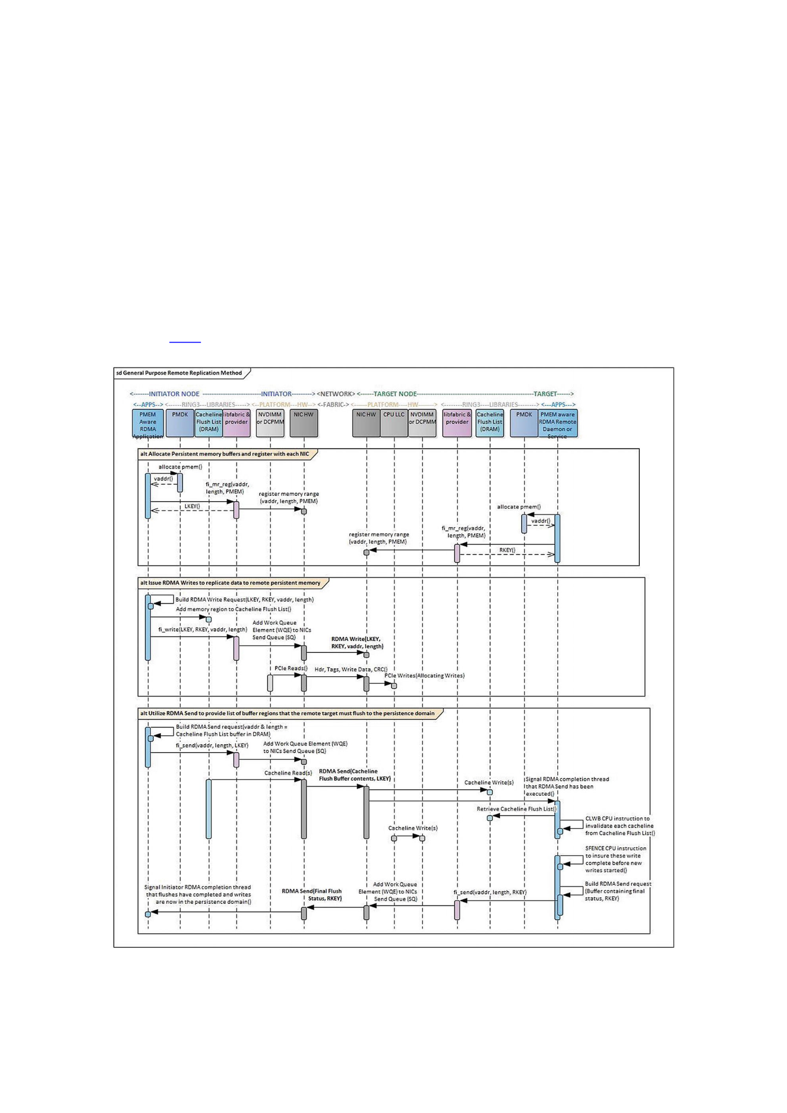
been written to with previous RDMA Write requests. When all remote writes to
persistent memory are issued, the application issues an RDMA Send request from the
initiator NIC to the target NIC. The RDMA Send request contains a list of virtual starting
addresses and lengths that the target system will consume when the application
software running on the target node interrupts the system to process the send request.
The application walks the list of regions, flushing each cache line in the requested region
to the persistent memory using an optimized flush machine instruction (CLWB,
CLFLUSHOPT, etc.). When complete, an SFENCE machine instruction is required to
fence those previous writes and force them to complete before handling additional
writes. The application on the target system then issues an RDMA Send request back to
interrupt the initiator software of the completed flush operations. This is an indicator to
the application that the previous writes were made persistent.
Figure 18-2 outlines the general-purpose remote replication method sequence of
operation.
Figure 18-2The general-purpose remote replication method

How Does the General-Purpose Remote Replication Method Make Data
Persistent?
After the RDMA Write or any number of writes have been sent, the write data will
either be in the L3 CPU cache (due to the default allocating writes) or persistent
memory (assuming it does not all fit in L3) with potentially some write data still
pending in NIC internal buffers. An RDMA Send request, by definition, will force
previous writes to be pushed out of the NIC to the target L3 CPU cache and interrupt the
target CPU. At this point, all previously issued RDMA Writes to persistent memory are
now in L3 or persistent memory. The RDMA Send request contains a list of cache lines
that the initiator is requesting the target system to flush to its persistence domain. The
target system issues optimized flush instructions to flush each cache line in the
list to the persistence domain. This is followed by an SFENCE to guarantee these writes
complete before new writes are handled. At this point, the previous writes that were
flushed in the RDMA Send list are now persistent.
Performance Implications of the General-Purpose Remote Replication
Method
The general-purpose remote replication method requires that RDMA of the initiator
software follows a number of RDMA Write(s) with an RDMA Send. After the target NIC
finishes flushing the requested regions, an RDMA Send from the target goes back to the
initiator to affirm that the initiator application can consider those writes persistent.
This additional send/receive/send/receive messaging has an effect on latency and
throughput to make the writes persistent and has 50% higher latency than the
appliance remote replication method. The extra messaging has an effect on overall
bandwidth and scalability of all the RDMA connections running on those NICs.
Also, if the size of the RDMA Write that needs to be made persistent is small, the
efficiency of the connection drops dramatically as the extra messaging overhead
becomes a significant component of the overall latency. Additionally, the target node
CPU and caches are consumed for that operation. The same data is essentially
transmitted twice: once from NIC (via PCIe) to the CPU L3 cache and then from the CPU
L3 cache to the memory controller (iMC).
Appliance Remote Replication Method
Users of persistent memory on an Intel platform can use non-allocating write flows
by enabling the feature on the specific PCI root complex where incoming writes from
the NIC will enter into the CPU’s internal fabric and out to the persistent memory. Using
the non-allocating write flow, the incoming RDMA Writes will bypass CPU caches and go
directly to the persistence domain. This means that writes do not need to be flushed to
the persistence domain by the target system CPU.
The I/O pipeline still needs to be flushed to the persistence domain. This is more
efficiently accomplished by issuing a small RDMA Read to any memory address on the
same RDMA connection as the RDMA Writes; the memory address does not need to be
one that was written or is persistent. The RDMA specification clearly states that an
RDMA Read will force the previous RDMA Writes to complete first. This ordering rule is
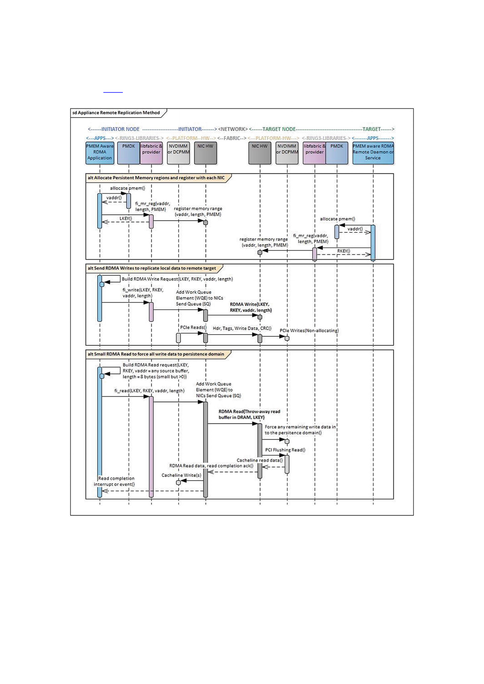
also true of the PCIe interconnect to which the target NIC is connected. PCIe Reads will
perform a pipeline flush and force previous PCIe writes to complete first.
Figure 18-3 outlines the basic appliance remote replication method, often referred
to as the appliance persistency method, described earlier.
Figure 18-3The appliance remote replication method
How Does the Appliance Remote Replication Method Make Data
Persistent?
The combination of bypassing CPU caches on the target system for the inbound
RDMA Writes to persistent memory with the ordering semantics of the RDMA and PCIe
protocols results in an efficient mechanism to make data persistent. Since the RDMA

Read to persistent memory will force previous writes first to persistent memory and the
persistence domain, the RDMA Read completion that comes back after those writes are
complete is the initiator application’s acknowledgment that those writes are now
durable.
Chapter 2 defines the persistence domain in depth, including how the platform
ensures that all writes get to the media from the persistence domain in the event of a
power loss.
Performance Implications of the Appliance Remote Replication Method
This single extra round trip using an RDMA Read is roughly 50% lower latency than
the general-purpose server persistency method, which requires two round-trip
messages before the writes can be declared durable. As with the first method, as the size
of the writes to be made durable gets smaller, the RDMA Read round-trip overhead
becomes a significant component of the overall latency.
General Software Architecture
The software stack for the use of remote persistent memory typically uses the same
memory-mapped files discussed in Chapter 3. Persistent memory is presented to the
RDMA application as a memory-mapped file. The application registers the persistent
memory with the local NIC on both ends of the connection, and the resulting registry
key is shared with the initiator application for use in the RDMA Read and Write
requests. This is the identical process required for using traditional volatile DRAM with
RDMA.
A layering of kernel and application-level software components is typically used to
allow an application to make use of both persistent memory and an RDMA connection.
The IBTA defines verbs interfaces that are typically implemented by the kernel drivers
for the NIC and the middleware software application library. Additional libraries may be
layered above the verbs layer to provide generic RDMA services via a common API- and
NIC-specific provider that implements the library.
On Linux, the Open Fabric Alliance (OFA) libibverbs library provides ring-3
interfaces to configure and use the RDMA connection for NICs that support IB, RoCE,
and iWARP RDMA network protocols. The OFA libfabric ring-3 application library can
be layered on top of libibverbs to provide a generic high-level common API that can be
used with typical RDMA NICs. This common API requires a provider plug-in to
implement the common API for the specific network protocol. The OFA web site
contains many example applications and performance tests that can be used on Linux
with a variety of RDMA-capable NICs. Those examples provide the backbone of the
PMDK librpmem library.
Windows implements remotely mounted NTFS volumes via the ring-3 SMB Direct
Application library, which provides a number of storage protocols including block
storage over RDMA.
Figure 18-4 provides the basic high-level architecture for a typical RDMA application
on Linux, using all of the publically available libraries and interfaces. Notice that a
separate side-band connection is typically needed to set up the RDMA connections
themselves.
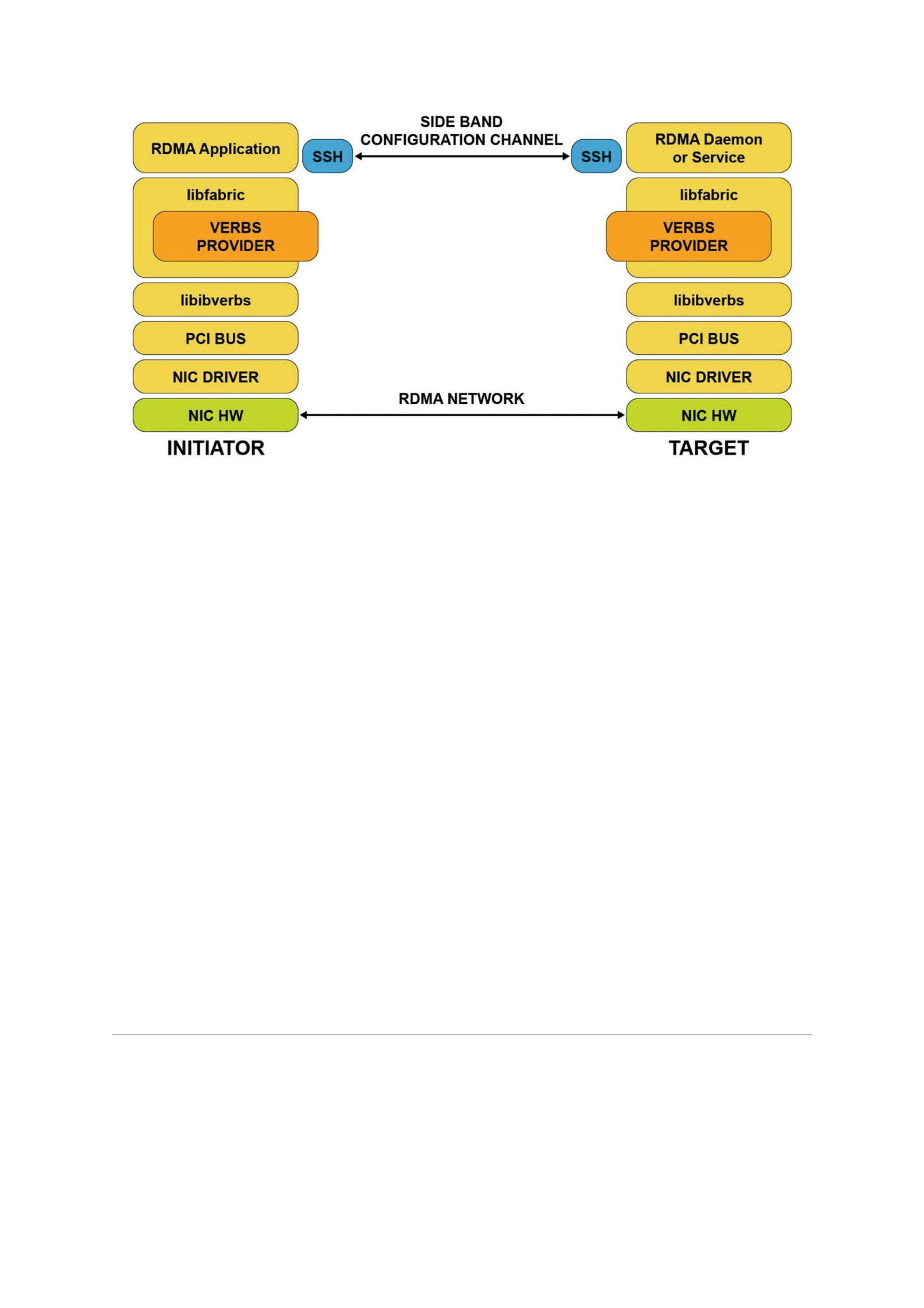
Figure 18-4General RDMA software architecture
ACPI-Defined Health Functions (_NCH, _NBS)
The ACPI specification includes two vendor-agnostic methods for operating systems
and management software to call for determining the health of a persistent memory
device.
Get NVDIMM Current Health Information (_NCH) can be called by the operating
systems at boot time to get the current health of the persistent memory device and take
appropriate action. The values reported by _NCH can change during runtime and should
be monitored for changes. _NCH contains health information that shows if
The persistent memory requires maintenance
The persistent memory device performance is degraded
The operating system can assume write persistency loss on subsequent
power events
The operating system can assume all data will be lost on subsequent power
events
Get NVDIMM Boot Status (_NBS) allows operating systems a vendor-agnostic
method to discover persistent memory health status that does not change during
runtime. The most significant attribute reported by _NBS is Data Loss Count (DLC). Data
Loss Count is expected to be used by applications and operating systems to help identify
the rare case where a persistent memory dirty shutdown has occurred. See
“Unsafe/Dirty Shutdown” later in this chapter for more information on how to properly
use this attribute.
Vendor-Specific Device Health (_DSMs)
Many vendors may want to add further health attributes beyond what exists in _NBS
and _NCH. Vendors are free to design their own ACPI persistent memory device-specific
methods (_DSM) to be called by the operating system and privileged applications.
Although vendors implement persistent memory health discovery differently, a few

common health attributes are likely to exist to determine if a persistent memory device
requires service. These health attributes may include information such as an overall
health summary of the persistent memory, current persistent memory temperature,
persistent media error counts, and total device lifetime utilization. Many operating
systems, such as Linux, include support to retrieve and report the vendor-unique health
statistics through tools such as ndctl. The Intel persistent memory _DSM interface
document can be found under the “Related Specification” section of
https://docs.pmem.io/.
ACPI NFIT Health Event Notification
Due to the potential loss of quality of service, operating systems and privileged
applications may not want to actively poll persistent memory devices to retrieve device
health. Thus, the ACPI specification has defined a passive notification method to allow
the persistent memory device to notify when a significant change in device health has
occurred. Persistent memory device vendors and platform BIOS vendors decide which
device health changes are significant enough to trigger an NVDIMM Firmware Interface
Table (NFIT) health event notification. Upon receipt of an NFIT health event, a
notification to the operating system is expected to call an _NCH or a _DSM attached to
the persistent memory device and take appropriate action based on the data returned.
Unsafe/Dirty Shutdown
An unsafe or dirty shutdown on persistent memory means that the persistent memory
device power-down sequence or platform power-down sequence may have failed to
write all in-flight data from the system’s persistence domain to persistent media.
(Chapter 2 describes persistence domains.) A dirty shutdown is expected to be a very
rare event, but they can happen due to a variety of reasons such as physical hardware
issues, power spikes, thermal events, and so on.
A persistent memory device does not know if any application data was lost as a
result of the incomplete power-down sequence. It can only detect if a series of events
occurred in which data may have been lost. In the best-case scenario, there might not
have been any applications that were in the process of writing data when the dirty
shutdown occurred.
librpmem Architecture and Its Use in Replication
PMDK implements both the general-purpose remote replication method and the
appliance remote replication method in the librpmem library. As of PMDK v1.7, the
librpmem library implements the synchronous and asynchronous replication of local
writes to persistent memory on remote systems. librpmem is a low-level library, like
libpmem, which allows other libraries to use its replication features.
libpmemobj uses a synchronous write model, meaning that the local initiator write
and all of the remotely replicated writes must complete before the local write will be
completed back to the application. The libpmemobj library also implements a simple
active-passive replication architecture, where all persistent memory transactions are
driven through the active initiator node and the remote targets passively standby,
replicating the write data. While the passive target systems have the latest write data
replicated, the implementation makes no attempt to fail over, fail back, or load balance
using the remote systems. The following sections describe the significant performance
drawbacks to this implementation.
libpmemobj uses the local memory pool configuration information provided in a
configuration file to describe the remote network–connected memory-mapped files. A
remote rpmemd program installed on each remote target system is started and
connected to the librpmem library on the initiator using a secure encrypted socket
connection. Through this connection, librpmem, on behalf of libpmemobj, will set up
the RDMA point-to-point connection with each target system, determine the persistence
method the target supports (general purpose or appliance method), allocate remote
memory-mapped persistent memory files, register the persistent memory on the
remote NIC, and retrieve the resulting memory keys for the registered memory.
Once all the RDMA connections to all the targets are established, all required queues
are instantiated, and memory buffers have all been allocated and registered, the
libpmemobj library is ready to begin remotely replicating all application write data
to its local memory-mapped file. When the application calls pmemobj_persist() in
libpmemobj, the library will generate a corresponding rpmem_persist() call into
librpmem which, in turn, calls the libfabric fi_write() to do the RDMA Write.
librpmem then initiates the RDMA Read or Send persistence method (as governed by
an understanding of the currently enabled target node’s current configuration) by
calling libfabric fi_read() or fi_send(). RDMA Read is used in the appliance
remote replication method, and RDMA Send is used in the general-purpose remote
replication method.
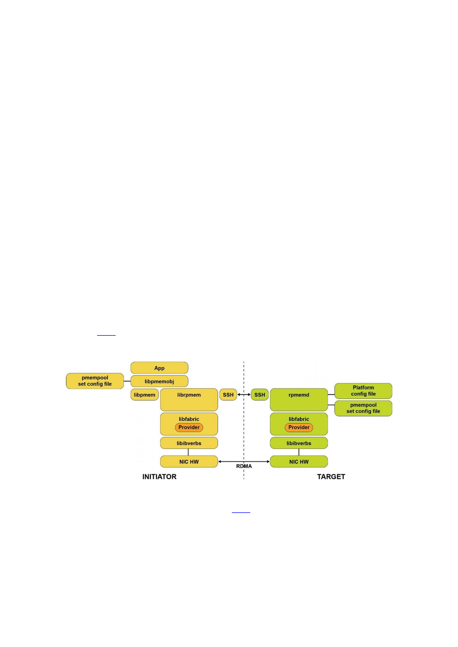
Figure 18-5 outlines the high-level components and interfaces described earlier and
used by both the initiator and remote target system using librpmem and
libpmemobj.
Figure 18-5RDMA architecture using libpmemobj and librpmem
The major components (shown in Figure 18-5) are described in the following to help
you understand the high-level architecture that is used by the PMDK’s remote
replication feature:
librpmem – PMDK Remote RDMA Access Library: The container for the initiator
node for all the initiator PMDK functionality that is related to remote replication using
RDMA.
rpmemd – PMDK Remote RDMA Configuration Daemon: The container for the target
node for all the target PMDK functionality that is related to remote replication using

RDMA. It will block any local access to the pmempool set that has been configured for
remote usage and executes the remote target interrupt handlers required for the
general-purpose remote replication method.
Initiator and Target SSH: This component is used by both librpmem and rpmemd
libraries to set up a simple socket connection, close a previously opened socket
connection, and send communication packets back and forth.
Libfabric: The OFA defined high-level ring-3 application API for setting up and using a
fabric connection in a fabric and vendor-agnostic way. This high-level interface
supports RoCE, InfiniBand, and iWARP, as well Intel Omni-Path Architecture products
and other network protocols using libfabric-specific transport providers.
Libibverbs: The OFA defined high-level RDMA fabric-based interface. This high-level
interface supports RoCE, InfiniBand, and iWARP and is commonly used in most Linux
distributions.
Target Node Platform Configuration File: Simple text file generated by the IT admin
or user to describe the platform capabilities of the remote target node. This file
describes specific capabilities that affect what durability method can be used, that is,
ADR-enabled platform, non-allocating write flows enabled by the NIC, and platform
type. It also specifies the default socket-connection port that rpmemd will listen on.
Initiator Node PMDK pmempool Set Configuration File: An existing persistent
memory poolset configuration file is generated by the system or application
administrator that describes local sets of files that will be treated as a pool of persistent
memory on the local platform. It also describes local files for local replication and
remote target hostnames for remote replication.
Target Node PMDK pmempool Set Configuration File: An existing persistent
memory poolset configuration file is generated by the system or application
administrator that describes local sets of files that will be treated as a pool of persistent
memory on the local platform. On the target node, this set is the collection of files that
the initiator node is replicating data into.
Initiator and Target Node Operating System syslog: The standard Linux syslog on
each node used by librpmem and rpmemd for outputting useful data for both debug
and non-debug information. Since there is little information from rpmemd that is visible
on the initiator system, extensive information will be output to the target system syslog
when rpmemd is started with the "-d" (debug) runtime option. Even without the
debug enabled, rpmemd will output socket events like open, close, create, lost
connection, and similar RDMA events.
Configuring Remote Replication Using Poolsets
You are probably already familiar with using poolsets (introduced in Chapter 7)
libpmemobj to initialize remote replication, which requires two such poolset files. The
file used on the initiator side by the libpmemobj-enabled application must describe
the local memory pool and point to poolset configuration file on the target node,
whereas the poolset file on the target node must describe the memory pool shared by
the target system.
Listing 18-1 shows a poolset file that will allow replicating local writes to the
“remotepool.set” on a remote host.
PMEMPOOLSET

256G /mnt/pmem0/pool1
REPLICA [email protected] remotepool.set
Listing 18-1poolwithremotereplica.set – An example of replicating local data to a remote host
Listing 18-2 shows a poolset file that describes the memory-mapped files shared for
the remote access. In many ways, a remote poolset file is the same as the regular poolset
file, but it must fulfill additional requirements:
Exist in a poolset directory specified in the rpmemd configuration file
Should be uniquely identified by its name, which an rpmem-enabled
application has to use to replicate to the specified memory pool
Cannot define any additional replicas, local or remote
PMEMPOOLSET
256G /mnt/pmem1/pool2
Listing 18-2remotereplica.set – An example of how to describe the memory pool on the remote host
Performance Considerations
Once persistent memory is accessible via a remote network connection, significantly
lower latency can be achieved compared with writing to a remote SSD or legacy block
storage device. This is because the RDMA hardware is writing the remote write data
directly into the final persistent memory location, whereas remote replication to an SSD
requires an RDMA Write into the DRAM on the remote server, followed by a second
local DMA operation to move the remote write data from volatile DRAM into the final
storage location on the SSD or other legacy block storage device.
The performance challenge with replicating data to remote persistent memory is
that while large block sizes of 512KiB or larger can achieve good performance, as the
size of the writes being replicated gets smaller, the network overhead becomes a larger
portion of the total latency, and performance can suffer.
If the persistent memory is being used as an SSD replacement, the typical native
block storage size is 4K, avoiding some of the inefficiencies seen with small transfers. If
the persistent memory replaces a traditional SSD and data is written remotely to the
SSD, the latency improvements with persistent memory can be 10x or more.
The synchronous replication model implemented in librpmem means that small
data structures and pointer updates in local persistent memory result in small, very
inefficient, RDMA Writes followed by a small RDMA Read or Send to make that small
amount of write data persistent. This results in significant performance degradation
compared to writing only to local persistent memory. It makes the replication
performance very dependent on the local persistent memory write sequences, which is
heavily dependent on the application workload. In general, the larger the average
request size and the lower the number of rpmem_persist() calls that are required
for a given workload will improve the overall latency required for guaranteeing that
data is persistent.
It is possible to follow multiple RDMA Writes with single RDMA Read or Send to
make all of the preceding writes persistent. This reduces the impact of the size of RDMA
Writes on the overall performance of the proposed solution. But using this mitigation,
remember you are not guaranteed that any of the RDMA Writes is persistent until
RDMA Read completion returns or you receive RDMA Send with a confirmation. The

implementation that allows this approach is implemented in rpmem_flush() and
rpmem_drain() API call pair, where rpmem_flush() performs RDMA Write and
returns immediately and rpmem_drain() posts RDMA Read and waits for its
completion (at the time of publication it is not implemented in the write/send model).
There are many performance considerations, including the high-level networking
model being used. Traditional best-in-class networking architecture typically relies on a
pull model between the initiator and target. In a pull model, the initiator requests
resources from the target, but the target server only pulls the data across via RDMA
Read when it has the resources and connection bandwidth. This server-centric view
allows the target node to handle hundreds or thousands of connections since it is in
complete control of all resources for all of the connections and initiates the networking
transactions when it chooses. With the speed and low latency of persistent memory, a
push model can be used where the initiator and target have pre-allocated and registered
memory resources and directly RDMA Write the data without waiting for server-side
resource coordination. Microsoft’s SNIA DevCon RDMA presentation describes the
push/pull model in more detail:
(https://www.snia.org/sites/default/files/SDC/2018/presentation
s/PM/Talpey_Tom_Remote_Persistent_Memory.pdf).
Remote Replication Error Handling
librpmem replication failures will occur for either a lost socket connection or a lost
RDMA connection. Any error status returned from rpmem_persist(),
rpmem_flush(), and rpmem_drain() is typically treated as an unrecoverable
failure. The libpmemobj user of librpmem API should treat this as a lost socket or
RDMA condition and should wait for all remaining librpmem API calls to complete, call
rpmem_close() to close the connection and clean up the stack, and then force the
application to exit. When the application restarts, the files will be reopened on both
ends, and libpmemobj will check only the file metadata. We recommend you do not
proceed before synchronizing local and remote memory pools with the pmempool-
sync(1) command.
Say Hello to the Replicated World
The beauty of the libpmemobj remote replication is that it does not require any
changes to the existing libpmemobj application. If you take any libpmemobj
application and provide it with the poolset file configured to use the remote replica, it
will simply start replicating. No coding required.
To illustrate how to replicate persistent memory, we look at a Hello World type
program demonstrating the replication process directly using the librpmem library.
Listing 18-3 shows a part of the C program that writes the “Hello world” message to
remote memory. If it discovers that the message in English is already there, it translates
it to Spanish and writes it back to remote memory. We walk through the lines of the
program at the end of the listing.
37 #include <assert.h>
38 #include <errno.h>

39 #include <unistd.h>
40 #include <stdio.h>
41 #include <stdlib.h>
42 #include <string.h>
43
44 #include <librpmem.h>
45
46 /*
47 * English and Spanish translation of the message
48 */
49 enum lang_t {en, es};
50 static const char *hello_str[] = {
51 [en] = "Hello world!",
52 [es] = "¡Hola Mundo!"
53 };
54
55 /*
56 * structure to store the current message
57 */
58 #define STR_SIZE 100
59 struct hello_t {
60 enum lang_t lang;
61 char str[STR_SIZE];
62 };
63
64 /*
65 * write_hello_str -- write a message to the local memory
66 */
67 static inline void
68 write_hello_str(struct hello_t *hello, enum lang_t lang)
69 {
70 hello->lang = lang;
71 strncpy(hello->str, hello_str[hello->lang], STR_SIZE);
72 }
104 int
105 main(int argc, char *argv[])
106 {
107 /* for this example, assume 32MiB pool */
108 size_t pool_size = 32 * 1024 * 1024;
109 void *pool = NULL;
110 int created;
111
112 /* allocate a page size aligned local memory pool */
113 long pagesize = sysconf(_SC_PAGESIZE);
114 assert(pagesize >= 0);
115 int ret = posix_memalign(&pool, pagesize, pool_size);
116 assert(ret == 0 && pool != NULL);

117
118 /* skip to the beginning of the message */
119 size_t hello_off = 4096; /* rpmem header size */
120 struct hello_t *hello = (struct hello_t *)(pool +
hello_off);
121
122 RPMEMpool *rpp = remote_open("target", "pool.set", pool,
pool_size,
123 &created);
124 if (created) {
125 /* reset local memory pool */
126 memset(pool, 0, pool_size);
127 write_hello_str(hello, en);
128 } else {
129 /* read message from the remote pool */
130 ret = rpmem_read(rpp, hello, hello_off, sizeof(*hello),
0);
131 assert(ret == 0);
132
133 /* translate the message */
134 const int lang_num = (sizeof(hello_str) /
sizeof(hello_str[0]));
135 enum lang_t lang = (enum lang_t)((hello->lang + 1) %
lang_num);
136 write_hello_str(hello, lang);
137 }
138
139 /* write message to the remote pool */
140 ret = rpmem_persist(rpp, hello_off, sizeof(*hello), 0, 0);
141 printf("%s\n", hello->str);
142 assert(ret == 0);
143
144 /* close the remote pool */
145 ret = rpmem_close(rpp);
146 assert(ret == 0);
147
148 /* release local memory pool */
149 free(pool);
150 return 0;
151 }
Listing 18-3The main routine of the Hello World program with replication
Line 68: Simple helper routine for writing message to the local memory.
Line 115: Allocate a big enough block of memory, which is aligned to the
page size. The required block size is hard-coded, whereas the alignment is
required if you want to make this memory block available for RDMA
transfers.
Line 122: The remote_open() routine creates or opens the remote
memory pool.

Lines 126-127: The local memory pool is initialized here. It is performed
only once when the remote memory pool was just created, so it does not
contain any message.
Line 130: A message from the remote memory pool is read to the local
memory here.
Lines 134-136: If a message from the remote memory pool was read
correctly, it is translated locally.
Line 140: The newly initialized or translated message is written to the
remote memory pool.
Line 145: Close the remote memory pool.
Line 149: Release remote memory pool.
The last missing piece of the whole process is how the remote replication is set up. It
is all done in the remote_open() routine presented in Listing 18-4.
74 /*
75 * remote_open -- setup the librpmem replication
76 */
77 static inline RPMEMpool*
78 remote_open(const char *target, const char *poolset, void
*pool,
79 size_t pool_size, int *created)
80 {
81 /* fill pool_attributes */
82 struct rpmem_pool_attr pool_attr;
83 memset(&pool_attr, 0, sizeof(pool_attr));
84 strncpy(pool_attr.signature, "HELLO",
RPMEM_POOL_HDR_SIG_LEN);
85
86 /* create a remote pool */
87 unsigned nlanes = 1;
88 RPMEMpool *rpp = rpmem_create(target, poolset, pool,
pool_size, &nlanes,
89 &pool_attr);
90 if (rpp) {
91 *created = 1;
92 return rpp;
93 }
94
95 /* create failed so open a remote pool */
96 assert(errno == EEXIST);
97 rpp = rpmem_open(target, poolset, pool, pool_size, &nlanes,
&pool_attr);
98 assert(rpp != NULL);
99 *created = 0;
100
101 return rpp;
102 }
Listing 18-4A remote_open routine from the Hello World program with replication

Line 88: A remote memory pool can be either created or opened. When it is
used for the first time, it must be created so that it is available for the
opening afterward. We first try to create it here.
Line 97: Here we attempt to open the remote memory pool. We assume it
exists because of the error code received during the create try (EEXIST).
Execution Example
The Hello World application produces the output shown in Listing 18-5.
[user@initiator]$ ./hello
Hello world!
[user@initiator]$ ./hello
¡Hola Mundo!
Listing 18-5An output from the Hello World application for librpmem
Listing 18-6 shows the contents of the target persistent memory pool where we see
the “Hola Mundo” string.
[user@target]$ hexdump –s 4096 –C /mnt/pmem1/pool2
00001000 01 00 00 00 c2 a1 48 6f 6c 61 20 4d 75 6e 64 6f
|......Hola Mundo|
00001010 21 00 00 00 00 00 00 00 00 00 00 00 00 00 00 00
|!...............|
00001020 00 00 00 00 00 00 00 00 00 00 00 00 00 00 00 00
|................|
*
00002000
Listing 18-6The ¡Hola Mundo! snooped on the replication target
Nonuniform Memory Access (NUMA)
NUMA is a computer memory design used in multiprocessing where the memory
access time depends on the memory location relative to the processor. NUMA is used in
a symmetric multiprocessing (SMP) system. An SMP system is a “tightly coupled and
share everything” system in which multiple processors working under a single
operating system can access each other’s memory over a common bus or “interconnect”
path. With NUMA, a processor can access its own local memory faster than nonlocal
memory (memory that is local to another processor or memory shared between
processors). The benefits of NUMA are limited to particular workloads, notably on
servers where the data is often associated strongly with certain tasks or users.
CPU memory access is always fastest when the CPU can access its local memory.
Typically, the CPU socket and the closest memory banks define a NUMA node.
Whenever a CPU needs to access the memory of another NUMA node, it cannot access it
directly but is required to access it through the CPU owning the memory. Figure 19-1
shows a two-socket system with DRAM and persistent memory represented as
“memory.”
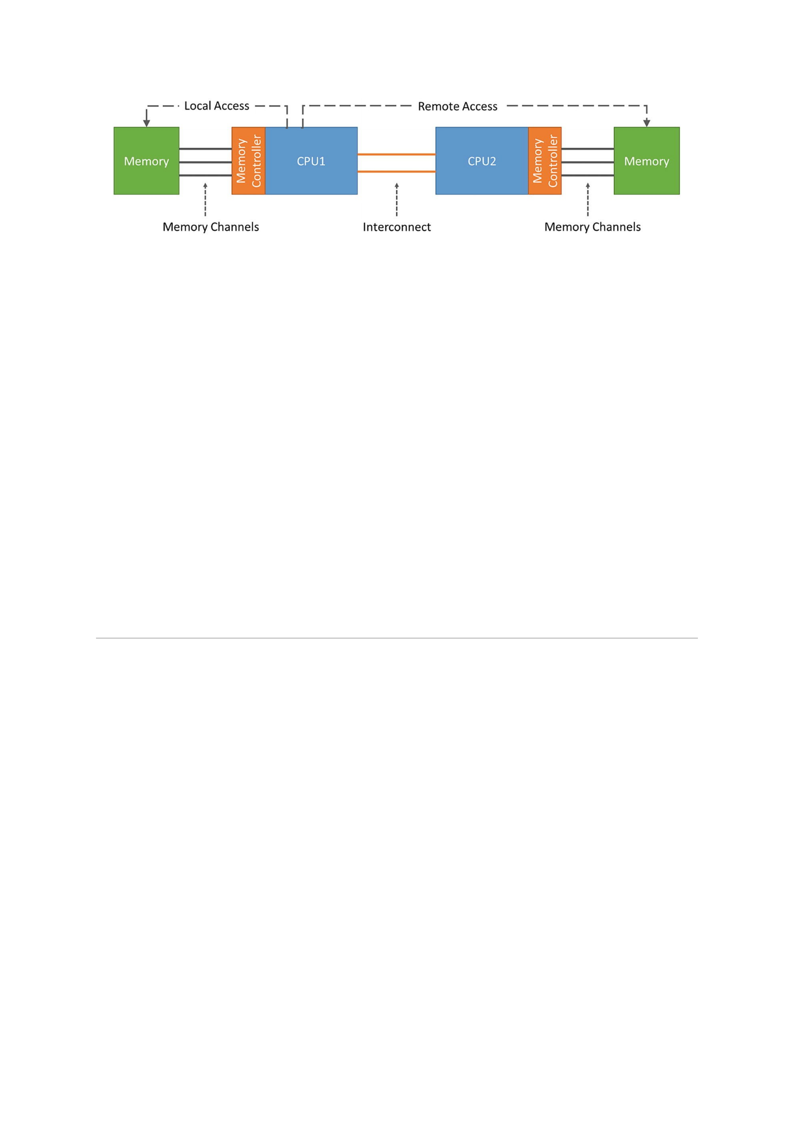
Figure 19-1A two-socket CPU NUMA architecture showing local and remote memory access
On a NUMA system, the greater the distance between a processor and a memory
bank, the slower the processor’s access to that memory bank. Performance-sensitive
applications should therefore be configured so they allocate memory from the closest
possible memory bank.
Performance-sensitive applications should also be configured to execute on a set
number of cores, particularly in the case of multithreaded applications. Because first-
level caches are usually small, if multiple threads execute on one core, each thread will
potentially evict cached data accessed by a previous thread. When the operating system
attempts to multitask between these threads, and the threads continue to evict each
other’s cached data, a large percentage of their execution time is spent on cache line
replacement. This issue is referred to as cache thrashing. We therefore recommend that
you bind a multithreaded application to a NUMA node rather than a single core, since
this allows the threads to share cache lines on multiple levels (first-, second-, and last-
level cache) and minimizes the need for cache fill operations. However, binding an
application to a single core may be performant if all threads are accessing the same
cached data. numactl allows you to bind an application to a particular core or NUMA
node and to allocate the memory associated with a core or set of cores to that
application.
NUMACTL Linux Utility
On Linux we can use the numactl utility to display the NUMA hardware
configuration and control which cores and threads application processes can run. The
libnuma library included in the numactl package offers a simple programming
interface to the NUMA policy supported by the kernel. It is useful for more fine-grained
tuning than the numactl utility. Further information is available in the numa(7) man
page.
The numactl --hardware command displays an inventory of the available
NUMA nodes within the system. The output shows only volatile memory, not persistent
memory. We will show how to use the ndctl command to show NUMA locality of
persistent memory in the next section. The number of NUMA nodes does not always
equal the number of sockets. For example, an AMD Threadripper 1950X has 1 socket
and 2 NUMA nodes. The following output from numactl was collected from a two-
socket Intel Xeon Platinum 8260L processor server with a total of 385GiB DDR4,
196GiB per socket.
# numactl --hardware
available: 2 nodes (0-1)

node 0 cpus: 0 1 2 3 4 5 6 7 8 9 10 11 12 13 14 15 16 17 18 19
20 21 22 23 48 49 50 51 52 53 54 55 56 57 58 59 60 61 62 63 64
65 66 67 68 69 70 71
node 0 size: 192129 MB
node 0 free: 187094 MB
node 1 cpus: 24 25 26 27 28 29 30 31 32 33 34 35 36 37 38 39
40 41 42 43 44 45 46 47 72 73 74 75 76 77 78 79 80 81 82 83 84
85 86 87 88 89 90 91 92 93 94 95
node 1 size: 192013 MB
node 1 free: 191478 MB
node distances:
node 0 1
0: 10 21
1: 21 10
The node distance is a relative distance and not an actual time-based latency in
nanoseconds or milliseconds.
numactl lets you bind an application to a particular core or NUMA node and
allocate the memory associated with a core or set of cores to that application. Some
useful options provided by numactl are described in Table 19-1.
Table 19-1numactl command options for binding processes to NUMA nodes or CPUs
Option Description
--membind, -m Only allocate memory from specific NUMA nodes. The allocation will fail if there is not enough
memory available on these nodes.
--cpunodebind,
-N
Only execute the process on CPUs from the specified NUMA nodes.
--physcpubind,
-C
Only execute process on the given CPUs.
--localalloc, -
l
Always allocate on the current NUMA node.
--preferred Preferably allocate memory on the specified NUMA node. If memory cannot be allocated, fall
back to other nodes.
NDCTL Linux Utility
The ndctl utility is used to create persistent memory capacity for the operating
system, called namespaces, as well as enumerating, enabling, and disabling the dimms,
regions, and namespaces. Using the –v (verbose) option shows what NUMA node
(numa_node) persistent memory DIMMS (-D), regions (-R), and namespaces (-N)
belong to. Listing 19-1 shows the region and namespaces for a two-socket system. We
can correlate the numa_node with the corresponding NUMA node shown by the
numactl command.
# ndctl list -Rv
{
"regions":[
{
"dev":"region1",

"size":1623497637888,
"available_size":0,
"max_available_extent":0,
"type":"pmem",
"numa_node":1,
"iset_id":-2506113243053544244,
"persistence_domain":"memory_controller",
"namespaces":[
{
"dev":"namespace1.0",
"mode":"fsdax",
"map":"dev",
"size":1598128390144,
"uuid":"b3e203a0-2b3f-4e27-9837-a88803f71860",
"raw_uuid":"bd8abb69-dd9b-44b7-959f-79e8cf964941",
"sector_size":512,
"align":2097152,
"blockdev":"pmem1",
"numa_node":1
}
]
},
{
"dev":"region0",
"size":1623497637888,
"available_size":0,
"max_available_extent":0,
"type":"pmem",
"numa_node":0,
"iset_id":3259620181632232652,
"persistence_domain":"memory_controller",
"namespaces":[
{
"dev":"namespace0.0",
"mode":"fsdax",
"map":"dev",
"size":1598128390144,
"uuid":"06b8536d-4713-487d-891d-795956d94cc9",
"raw_uuid":"39f4abba-5ca7-445b-ad99-fd777f7923c1",
"sector_size":512,
"align":2097152,
"blockdev":"pmem0",
"numa_node":0
}
]
}
]
}

Listing 19-1Region and namespaces for a two-socket system
Intel Memory Latency Checker Utility
To get absolute latency numbers between NUMA nodes on Intel systems, you can
use the Intel Memory Latency Checker (Intel MLC), available from
https://software.intel.com/en-us/articles/intel-memory-
latency-checker.
Intel MLC provides several modes specified through command-line arguments:
--latency_matrix prints a matrix of local and cross-socket memory
latencies.
--bandwidth_matrix prints a matrix of local and cross-socket memory
bandwidths.
--peak_injection_bandwidth prints peak memory bandwidths of the
platform for various read-write ratios.
--idle_latency prints the idle memory latency of the platform.
--loaded_latency prints the loaded memory latency of the platform.
--c2c_latency prints the cache-to-cache data transfer latency of the
platform.
Executing mlc or mlc_avx512 with no arguments runs all the modes in sequence
using the default parameters and values for each test and writes the results to the
terminal. The following example shows running just the latency matrix on a two-socket
Intel system.
# ./mlc_avx512 --latency_matrix -e -r
Intel(R) Memory Latency Checker - v3.6
Command line parameters: --latency_matrix -e -r
Using buffer size of 2000.000MiB
Measuring idle latencies (in ns)...
Numa node
Numa node 0 1
0 84.2 141.4
1 141.5 82.4
--latency_matrix prints a matrix of local and cross-socket memory
latencies.
-e means that the hardware prefetcher states do not get modified.
-r is random access reads for latency thread.
MLC can be used to test persistent memory latency and bandwidth in either DAX or
FSDAX modes. Commonly used arguments include
-L requests that large pages (2MB) be used (assuming they have been
enabled).
-h requests huge pages (1GB) for DAX file mapping.
-J specifies a directory in which files for mmap will be created (by default no
files are created). This option is mutually exclusive with –j.
-P CLFLUSH is used to evict stores to persistent memory.
Examples:
Sequential read latency:
# mlc_avx512 --idle_latency –J/mnt/pmemfs

Random read latency:
# mlc_avx512 --idle_latency -l256 –J/mnt/pmemfs
NUMASTAT Utility
The numastat utility on Linux shows per NUMA node memory statistics for
processors and the operating system. With no command options or arguments, it
displays NUMA hit and miss system statistics from the kernel memory allocator. The
default numastat statistics shows per-node numbers, in units of pages of memory, for
example:
$ sudo numastat
node0 node1
numa_hit 8718076 7881244
numa_miss 0 0
numa_foreign 0 0
interleave_hit 40135 40160
local_node 8642532 2806430
other_node 75544 5074814
numa_hit is memory successfully allocated on this node as intended.
numa_miss is memory allocated on this node despite the process
preferring some different node. Each numa_miss has a numa_foreign on
another node.
numa_foreign is memory intended for this node but is actually allocated
on a different node. Each numa_foreign has a numa_miss on another
node.
interleave_hit is interleaved memory successfully allocated on this
node as intended.
local_node is memory allocated on this node while a process was running
on it.
other_node is memory allocated on this node while a process was
running on another node.
Intel VTune Profiler – Platform Profiler
On Intel systems, you can use the Intel VTune Profiler - Platform Profiler, previously
called VTune Amplifier, (discussed in Chapter 15) to show CPU and memory statistics,
including hit and miss rates of CPU caches and data accesses to DDR and persistent
memory. It can also depict the system’s configuration to show what memory devices are
physically located on which CPU.
IPMCTL Utility
Persistent memory vendor- and server-specific utilities can also be used to show DDR
and persistent memory device topology to help identify what devices are associated
with which CPU sockets. For example, the ipmctl show –topology command
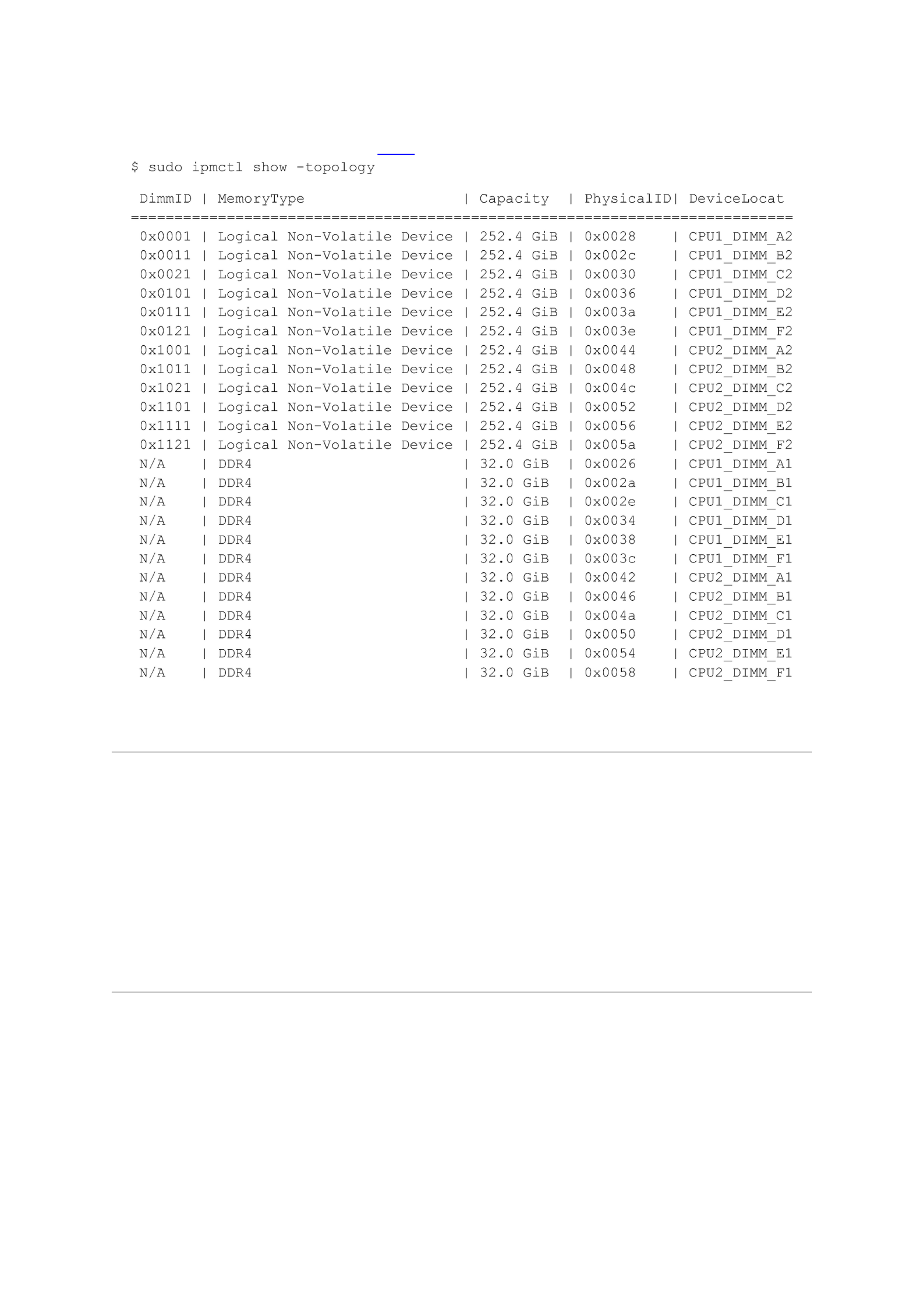
displays the DDR and persistent memory (non-volatile) devices with their physical
memory slot location (see Figure 19-2), if that data is available.
Figure 19-2Topology report from the ipmctl show –topology command
BIOS Tuning Options
The BIOS contains many tuning options that change the behavior of CPU, memory,
persistent memory, and NUMA. The location and name may vary between server
platform types, server vendors, persistent memory vendors, or BIOS versions. However,
most applicable tunable options can usually be found in the Advanced menu under
Memory Configuration and Processor Configuration. Refer to your system BIOS user
manual for descriptions of each available option. You may want to test several BIOS
options with the application(s) to understand which options bring the most value.
Automatic NUMA Balancing
Physical limitations to hardware are encountered when many CPUs and a lot of
memory are required. The important limitation is the limited communication
bandwidth between the CPUs and the memory. The NUMA architecture modification
addresses this issue. An application generally performs best when the threads of its
processes are accessing memory on the same NUMA node as the threads are scheduled.
Automatic NUMA balancing moves tasks (which can be threads or processes) closer to

the memory they are accessing. It also moves application data to memory closer to the
tasks that reference it. The kernel does this automatically when automatic NUMA
balancing is active. Most operating systems implement this feature. This section
discusses the feature on Linux; refer to your Linux distribution documentation for
specific options as they may vary.
Automatic NUMA balancing is enabled by default in most Linux distributions and
will automatically activate at boot time when the operating system detects it is running
on hardware with NUMA properties. To determine if the feature is enabled, use the
following command:
$ sudo cat /proc/sys/kernel/numa_balancing
A value of 1 (true) indicates the feature is enabled, whereas a value of 0 (zero/false)
means it is disabled.
Automatic NUMA balancing uses several algorithms and data structures, which are
only active and allocated if automatic NUMA balancing is active on the system, using a
few simple steps:
A task scanner periodically scans the address space and marks the memory
to force a page fault when the data is next accessed.
The next access to the data will result in a NUMA Hinting Fault. Based on this
fault, the data can be migrated to a memory node associated with the thread
or process accessing the memory.
To keep a thread or process, the CPU it is using and the memory it is
accessing together, the scheduler groups tasks that share data.
Manual NUMA tuning of applications using numactl will override any system-wide
automatic NUMA balancing settings. Automatic NUMA balancing simplifies tuning
workloads for high performance on NUMA machines. Where possible, we recommend
statically tuning the workload to partition it within each node. Certain latency-sensitive
applications, such as databases, usually work best with manual configuration. However,
in most other use cases, automatic NUMA balancing should help performance.
ACPI-Defined Health Functions (_NCH, _NBS)
The ACPI specification includes two vendor-agnostic methods for operating systems
and management software to call for determining the health of a persistent memory
device.
Get NVDIMM Current Health Information (_NCH) can be called by the operating
systems at boot time to get the current health of the persistent memory device and take
appropriate action. The values reported by _NCH can change during runtime and should
be monitored for changes. _NCH contains health information that shows if
The persistent memory requires maintenance
The persistent memory device performance is degraded
The operating system can assume write persistency loss on subsequent
power events
The operating system can assume all data will be lost on subsequent power
events
Get NVDIMM Boot Status (_NBS) allows operating systems a vendor-agnostic
method to discover persistent memory health status that does not change during
runtime. The most significant attribute reported by _NBS is Data Loss Count (DLC). Data
Loss Count is expected to be used by applications and operating systems to help identify

the rare case where a persistent memory dirty shutdown has occurred. See
“Unsafe/Dirty Shutdown” later in this chapter for more information on how to properly
use this attribute.
Vendor-Specific Device Health (_DSMs)
Many vendors may want to add further health attributes beyond what exists in _NBS
and _NCH. Vendors are free to design their own ACPI persistent memory device-specific
methods (_DSM) to be called by the operating system and privileged applications.
Although vendors implement persistent memory health discovery differently, a few
common health attributes are likely to exist to determine if a persistent memory device
requires service. These health attributes may include information such as an overall
health summary of the persistent memory, current persistent memory temperature,
persistent media error counts, and total device lifetime utilization. Many operating
systems, such as Linux, include support to retrieve and report the vendor-unique health
statistics through tools such as ndctl. The Intel persistent memory _DSM interface
document can be found under the “Related Specification” section of
https://docs.pmem.io/.
ACPI NFIT Health Event Notification
Due to the potential loss of quality of service, operating systems and privileged
applications may not want to actively poll persistent memory devices to retrieve device
health. Thus, the ACPI specification has defined a passive notification method to allow
the persistent memory device to notify when a significant change in device health has
occurred. Persistent memory device vendors and platform BIOS vendors decide which
device health changes are significant enough to trigger an NVDIMM Firmware Interface
Table (NFIT) health event notification. Upon receipt of an NFIT health event, a
notification to the operating system is expected to call an _NCH or a _DSM attached to
the persistent memory device and take appropriate action based on the data returned.
Unsafe/Dirty Shutdown
An unsafe or dirty shutdown on persistent memory means that the persistent memory
device power-down sequence or platform power-down sequence may have failed to
write all in-flight data from the system’s persistence domain to persistent media.
(Chapter 2 describes persistence domains.) A dirty shutdown is expected to be a very
rare event, but they can happen due to a variety of reasons such as physical hardware
issues, power spikes, thermal events, and so on.
A persistent memory device does not know if any application data was lost as a
result of the incomplete power-down sequence. It can only detect if a series of events
occurred in which data may have been lost. In the best-case scenario, there might not
have been any applications that were in the process of writing data when the dirty
shutdown occurred.
Using Volume Managers with Persistent Memory

We can provision persistent memory as a block device on which a file system can be
created. Applications can access persistent memory using standard file APIs or memory
map a file from the file system and access the persistent memory directly through
load/store operations. The accessibility options are described in Chapters 2 and 3.
The main advantages of volume managers are increased abstraction, flexibility, and
control. Logical volumes can have meaningful names like “databases” or “web.” Volumes
can be resized dynamically as space requirements change and migrated between
physical devices within the volume group on a running system.
On NUMA systems, there is a locality factor between the CPU and the DRR and
persistent memory that is directly attached to it. Accessing memory on a different CPU
across the interconnect incurs a small latency penalty. Latency-sensitive applications,
such as databases, understand this and coordinate their threads to run on the same
socket as the memory they are accessing.
Compared with SSD or NVMe capacity, persistent memory is relatively small. If your
application requires a single file system that consumes all persistent memory on the
system rather than one file system per NUMA node, a software volume manager can be
used to create concatenations or stripes (RAID0) using all the system’s capacity. For
example, if you have 1.5TiB of persistent memory per CPU socket on a two-socket
system, you could build a concatenation or stripe (RAID0) to create a 3TiB file system. If
local system redundancy is more important than large file systems, mirroring (RAID1)
persistent memory across NUMA nodes is possible. In general, replicating the data
across physical servers for redundancy is better. Chapter 18 discusses remote
persistent memory in detail, including using remote direct memory access (RDMA) for
data transfer and replication across systems.
There are too many volume manager products to provide step-by-step recipes for all
of them within this book. On Linux, you can use Device Mapper (dmsetup), Multiple
Device Driver (mdadm) , and Linux Volume Manager (LVM) to create volumes that use
the capacity from multiple NUMA nodes. Because most modern Linux distributions
default to using LVM for their boot disks, we assume that you have some experience
using LVM. There is extensive information and tutorials within the Linux documentation
and on the Web.
Figure 19-3 shows two regions on which we can create either an fsdax or sector
type namespace that creates the corresponding /dev/pmem0 and /dev/pmem1
devices. Using /dev/pmem[01], we can create an LVM physical volume which we then
combine to create a volume group. Within the volume group, we are free to create as
many logical volumes of the requested size as needed. Each logical volume can support
one or more file systems.
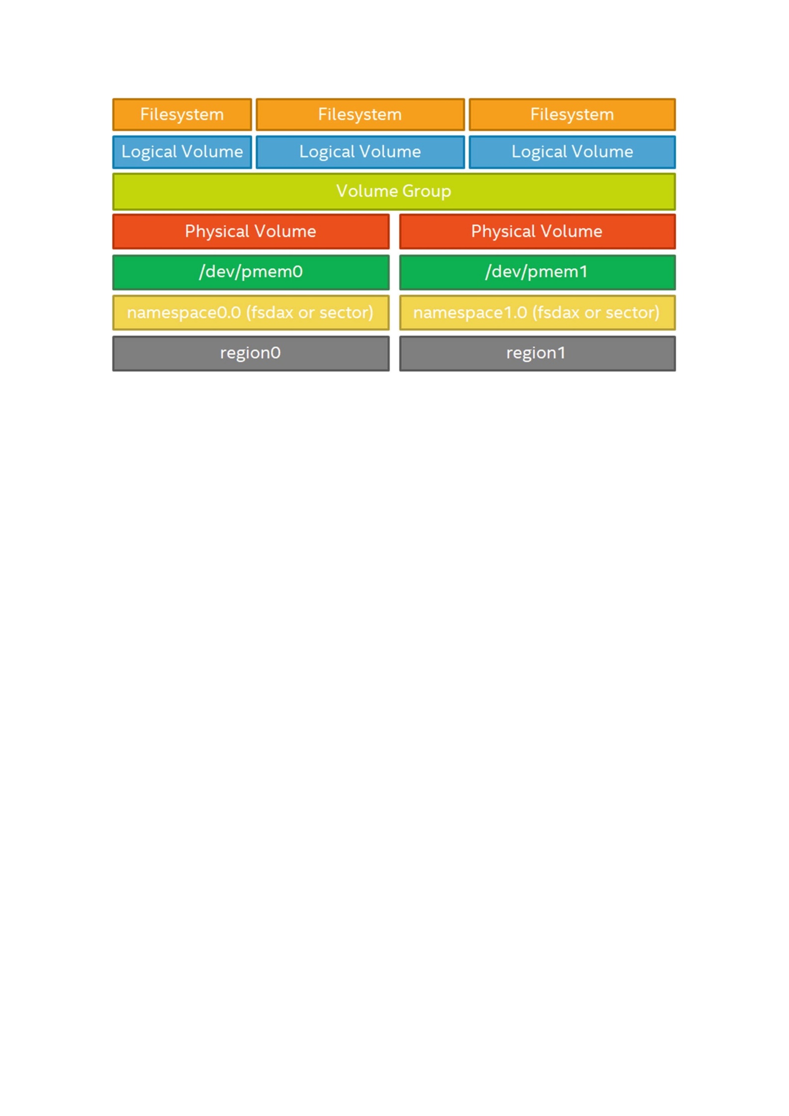
Figure 19-3Linux Volume Manager architecture using persistent memory regions and namespaces
We can also create a number of possible configurations if we were to create multiple
namespaces per region or partition the /dev/pmem* devices using fdisk or parted,
for example. Doing this provides greater flexibility and isolation of the resulting logical
volumes. However, if a physical NVDIMM fails, the impact is significantly greater since it
would impact some or all of the file systems depending on the configuration.
Creating complex RAID volume groups may protect the data but at the cost of not
efficiently using all the persistent memory capacity for data. Additionally, complex RAID
volume groups do not support the DAX feature that some applications may require.
The mmap( ) MAP_SYNC Flag
Introduced in the Linux kernel v4.15, the MAP_SYNC flag ensures that any needed file
system metadata writes are completed before a process is allowed to modify directly
mapped data. The MAP_SYNC flag was added to the mmap() system call to request the
synchronous behavior; in particular, the guarantee provided by this flag is
While a block is writeably mapped into page tables of this mapping, it is guaranteed to be
visible in the file at that offset also after a crash.
This means the file system will not silently relocate the block, and it will ensure that
the file’s metadata is in a consistent state so that the blocks in question will be present
after a crash. This is done by ensuring that any needed metadata writes were done
before the process is allowed to write pages affected by that metadata.
When a persistent memory region is mapped using MAP_SYNC, the memory
management code will check to see whether there are metadata writes pending for the
affected file. However, it will not actually flush those writes out. Instead, the pages are
mapped read only with a special flag, forcing a page fault when the process first
attempts to perform a write to one of those pages. The fault handler will then
synchronously flush out any dirty metadata, set the page permissions to allow the write,
and return. At that point, the process can write the page safely, since all the necessary
metadata changes have already made it to persistent storage.

The result is a relatively simple mechanism that will perform far better than the
currently available alternative of manually calling fsync() before each write to
persistent memory. The additional IO from fsync() can potentially cause the process
to block in what was supposed to be a simple memory write, introducing latency that
may be unexpected and unwanted.
The mmap(2) man page in the Linux Programmer’s manual describes the
MAP_SYNC flag as follows:
MAP_SYNC (since Linux 4.15)
This flag is available only with the MAP_SHARED_VALIDATE mapping type; mappings of
type MAP_SHARED will silently ignore this flag. This flag is supported only for files
supporting DAX (direct mapping of persistent memory). For other files, creating a
mapping with this flag results in an EOPNOTSUPP error.
Shared file mappings with this flag provide the guarantee that while some memory is
writably mapped in the address space of the process, it will be visible in the same file at the
same offset even after the system crashes or is rebooted. In conjunction with the use of
appropriate CPU instructions, this provides users of such mappings with a more efficient
way of making data modifications persistent.

