

Final Control Lab
 wmspikparona
Instrumentation Measurement & Lab
Final Control Lab
- The SCR in Figure 1 below requires a 3 V trigger. Using Multsim, design a system by which the gears are shifted when a CdS photocell resistance drops below 4kohms.
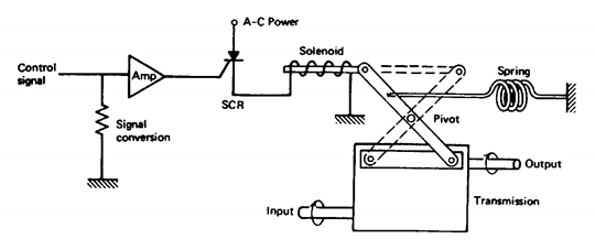
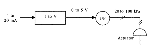
Figure 1 - Using Multisim, design a system by which a control signal of 4 to 20 mA is converted into a force of 200 to 1000N. Use a pneumatic actuator and specify the required diaphragm area if the pressure output is to be in the range of 20 to 100kPa. An I/P converter is available that converts 0 to 5 V into 20 to 100 kPa. A block diagraph of the system is shown below. (Hint: Use a differential amplifier. You are only designing the circuit to interface into the I/P below)
 9 years ago
 10
10
Answer(2)![blurred-text]()
![blurred-text]()

Purchase the answer to view it

NOT RATED
 report.docx
- 2.ms11
- 1.ms11
Purchase the answer to view it
NOT RATED
- finalcontrol2.ms14
- finalcontrol1.ms14
- finalcontrollab.docx
- finalcontrollab.rtf
other Questions(10)
- rebuild/expand your company’s Information and Communication Technology infrastructure and information system
- UNIX machine using the Sleuth forensic tools
- Prevention of Medication Errors
- Legal Process paper
- Module 2, Chapter 3 Review
- cell A takes 6 h to complete division. cell B takes 8 h to complete division . After 24 h...
- SCI 115 Assignment 2: Gene Technology
- Assignment 3: Cultural Activity Report
- Criminal Justice Questions
- Wk 2 RESPONSES