



PHYS 231 - UNIVERSITY PHYSICS I
- Equilibrium and Elasticity
Question Bank - Set 5
Liberty University
Question 1
Question
A uniform rod of length Land mass Mis suspended horizontally from one end.
A weight of mass mis hung from the other end of the rod. Find the distance
from the suspension point to the center of mass of the rod-weight system.
Solution
Let’s denote the distance from the suspension point to the center of mass of the
rod as x. To solve for x, we need to find the condition for the system to be in
equilibrium.
Step 1: Write out the condition for equilibrium in the vertical direction.
The net torque about the suspension point must be zero for the system to
be in equilibrium. This gives us the equation:
Xτ= 0
Step 2: Calculate the torque due to the weight mabout the suspension
point.
The torque τmdue to the weight mabout the suspension point is given by:
τm=m·g·L
where gis the acceleration due to gravity. The torque is positive since it
causes a clockwise rotation.
Step 3: Calculate the torque due to the rod about the suspension point.
The torque τMdue to the rod about the suspension point is given by:
τM=M
2·g·x

This torque is negative since it causes a counterclockwise rotation.
Step 4: Set up the equilibrium condition.
Setting the sum of torques equal to zero gives us:
τm+τM= 0
m·g·L−M
2·g·x= 0
Step 5: Solve for the distance x.
Solving for xgives us:
M
2·x=m·L
x=2·m·L
M
Hence, the distance from the suspension point to the center of mass of the
rod-weight system is 2·m·L
M.
Question 2
Question
A uniform rod of length Land mass Mis pivoted about a horizontal, frictionless
pin passing through one end of the rod. The rod is held horizontally and then
released. What is the angular acceleration of the rod just after it is released?
Solution
Let’s denote the distance from the pivot point to the center of mass of the rod
as d.
Step 1: Find the torque acting on the rod just after it is released. The
torque (τ) acting on the rod is given by the formula: τ=Iα, where Iis the
moment of inertia of the rod and αis the angular acceleration. The moment
of inertia of a rod rotating about one end is I=1
3ML2. The torque about the
pivot point is due to the force of gravity acting on the center of mass, and it
can be calculated as τ=−Mgd sin θ, where gis the acceleration due to gravity
and θis the angle the rod makes with the vertical.
Step 2: Apply the rotational equilibrium condition. For the rod to be in
equilibrium at any moment, the net torque acting on it must be zero. Thus, we
have −M gd sin θ=1
3ML2α. Observe that sin θcan be related to αas sin θ=a
d,
where ais the acceleration of the center of mass. Also, a=rα, and in this case
r=L
2.
Step 3: Substitute known values and solve for angular acceleration. Sub-
stitute d=L
2and g= 9.81 m/s2into the equation: −M g L
2a
L
2=1
3ML2α.
2

Simplify to get: −Mga =1
3ML2α. Cancel out the mass Mto get: −ga =1
3Lα.
Rearrange the equation to solve for α:α=−3g.
Step 4: Calculate the value of angular acceleration. Now, substitute g=
9.81 m/s2to find the angular acceleration: α=−3×9.81 = −29.43 rad/s2.
Therefore, the angular acceleration of the rod just after it is released is
α=−29.43 rad/s2.
Question 3
Question
A 2 m long uniform beam with a mass of 15 kg is suspended horizontally by
two ropes attached to its ends. A 7 kg weight is hung from a point on the beam
that is 1 m from one of the rope attachments. Determine the tensions in the
two ropes.
Solution
Step 1: Draw a free-body diagram of the beam and write down the forces acting
on it. Let T1and T2be the tensions in the ropes at each end of the beam, and
Wbe the weight hanging from the beam.
Step 2: Apply the equilibrium condition in the horizontal direction. The
sum of the forces in the horizontal direction is zero.
T1=T2
Step 3: Apply the equilibrium condition in the vertical direction. The sum
of the forces in the vertical direction is zero.
T1+T2=W
Step 4: Write the equations for the torque equilibrium. The beam will
remain in rotational equilibrium when the sum of the torques about any point
is zero. Let’s consider the point where Wis hanging.
T1·2 m = W·1 m
Step 5: Substitute T1=T2into the equation T1+T2=Wand solve for T1.
2T1=W=⇒T1=W
2
Step 6: Substitute T1=W
2into the equation T1·2 m = W·1 m and solve
for W.
W
2·2 m = W·1 m =⇒W= 30 N
3

Step 7: Finally, substitute W= 30 N into T1=W
2to find the tension in the
ropes.
T1=30 N
2= 15 N
Therefore, the tensions in the two ropes are both 15 N.
Question 4
Question
A uniform rod of length Land mass Mis hanging vertically from a frictionless
pivot point a distance dfrom its end. A massless spring with spring constant kis
attached to the lower end of the rod. If the system is in equilibrium, determine
the extension of the spring.
Solution
Let’s denote the extension of the spring as x, and the angle between the rod
and the vertical as θ.
Step 1: Find the torque equation.
The sum of the torques about the pivot point must be zero for the system
to be in equilibrium. The torque due to the force of gravity acting on the rod
and the torque due to the spring force must balance each other.
Sum of torques:
Mg L
2−dsin θ=kxL cos θ
Step 2: Find the force balance equation.
The sum of the vertical forces must also be zero for the system to be in
equilibrium. The upward force from the spring must balance the downward
force due to the weight of the rod.
Sum of vertical forces:
Mg =kx sin θ
Step 3: Eliminate θfrom the equations.
From the force balance equation, we have sin θ=Mg
kx . Substituting this into
the torque equation, we get:
Mg L
2−dMg
kx =kxL cos θ
Step 4: Solve for x.
Solving for xgives us:
x=rMg(L/2−d)
k
Therefore, the extension of the spring when the system is in equilibrium is
x=qMg(L/2−d)
k.
4

Question 5
Question
A block of mass mis hanging from a vertical spring with spring constant k.
When the block is in equilibrium, the spring is stretched by a distance x. If the
block is pulled a small distance dx below the equilibrium position and released,
find the period of its resulting oscillation.
Solution
Step 1: Find the force constant due to gravity when the block is displaced by
dx. The force constant due to gravity is given by F=mg, where mis the mass
of the block and gis the acceleration due to gravity. Since the block is displaced
by dx below equilibrium, the restoring force due to gravity is mg +k(dx −x).
Step 2: Apply Hooke’s Law to find the acceleration at displacement dx.
Hooke’s Law states that the force exerted by a spring is proportional to the
displacement. Therefore, k(dx −x) is the force exerted by the spring. Using
Newton’s second law, F=ma, we have:
mg +k(dx −x) = ma
Solving for a, we get:
a=g+k
m(dx −x)
Step 3: Find the time period of oscillation. Since the motion is simple
harmonic, we know that a=−ω2x, where ωis the angular frequency. From
Step 2, we can substitute the expression for ato obtain the differential equation:
g+k
m(dx −x) = −ω2x
Solving for ω, we have:
ω=rk
m
Step 4: Determine the time period T. The time period of oscillation Tis
related to the angular frequency ωby T=2π
ω. Substituting the value of ωwe
found in Step 3, we get:
T=2π
qk
m
Therefore, the period of oscillation is T= 2πpm
k.
5

Question 6
Question
A uniform beam of mass Mand length Lis supported by a cable attached to
its end. The beam is also supported by a horizontal force at a distance xfrom
the cable, as shown in the diagram below. The beam has a mass mplaced at a
distance L
4from the cable. If the tension in the cable is T, find the tension in
the cable.
[Diagram: a rectangular beam with length Lsupported by a cable at one
end, attached to a horizontal force Fat a distance xfrom the cable. A mass m
is placed at a distance L
4from the cable.]
Solution
Step 1: By considering the torques acting on the beam, we can write the equa-
tion for rotational equilibrium:
Xτ= 0
The torques acting on the beam are due to the forces T,F, and the weight of
the beam Mg acting at the center of mass. Let’s consider the torques about the
left end where the cable is attached.
Step 2: The torque due to the tension Tabout the left end is T·L. The
torque due to the force Fis F·(L−x). The torque due to the weight of the
beam is L
2·Mg. The torque due to the weight mis L
4·mg.
Step 3: Setting up the torque equation, we have:
T·L−F·(L−x)−L
2·Mg −L
4·mg = 0
Step 4: Now, we can isolate the tension Tin the cable from the torque
equation. Rearranging terms, we get:
T=F·L−x
L+Mg
2+mg
4
Step 5: We have expressed the tension in the cable Tin terms of the applied
horizontal force F, the distances xand L
4, as well as the mass of the beam and
the additional mass m. This is our final expression for the tension in the cable.
Question 7
Question
A uniform rod of length Land mass Mis supported horizontally at two points,
a distance aapart. A weight Wis hung a distance bfrom one end of the rod.
Determine the horizontal force Fthat must be applied at the other end of the
rod to keep it in equilibrium.
6

Solution
Step 1: First, we need to draw the free body diagram of the rod and apply
the condition for rotational equilibrium. Let Fbe the horizontal force and R1
and R2be the reaction forces at the supports. The weight of the rod can be
assumed to act at its center of mass, which is at a distance L/2 from each end.
The weight Wacts at a distance bfrom one end. The torques from these three
forces should sum to zero to maintain equilibrium. Step 2: The torque equation
for the rod is: −F·(L−a) + R1·a−W·b= 0. Step 3: Next, we need to
form the force balance equation. The forces in the vertical direction must cancel
out, so R1+R2−W−M·g= 0. Since the rod is in equilibrium, R1=W
and R2=Mg. Step 4: Substituting R1=Wand R2=Mg into the torque
equation, we get −F·(L−a) + W·a−W·b= 0. Step 5: Solving for F, we
find F=W(b−a)
L. Therefore, the horizontal force Fthat must be applied at the
other end of the rod to keep it in equilibrium is W(b−a)
L.
Question 8
Question
A rod of length Land mass Mis pivoted about one end. A force Fis applied
perpendicular to the other end of the rod at a distance dfrom the pivot point.
Find the tension in the rod and the acceleration of the pivot point in terms of
F,L,d, and M.
Solution
Step 1: Draw a free-body diagram of the rod. The forces acting on the rod are
the tension Tin the rod and the force Fapplied at a distance dfrom the pivot.
Step 2: Write the torque equation about the pivot point. The torque due to
the force Fis given by:
τF=F·d
The torque due to the tension Tis given by:
τT=T·L
Since the rod is in equilibrium, the total torque about the pivot point must be
zero, so:
τF=τT
Step 3: Set up and solve the torque equation.
F·d=T·L
Solving for Tgives:
T=F·d
L
7

Step 4: Use Newton’s second law to find the acceleration of the pivot point.
Since the rod is in equilibrium, the net force acting on it is zero. The tension T
and the force Fare the only forces acting in the horizontal direction. Therefore:
T=F
Now, use Newton’s second law for rotation about the pivot point:
T·L=I·α
where Iis the moment of inertia of the rod about the pivot point and αis the
angular acceleration of the rod. Since the rod is pivoted at one end, the moment
of inertia Iis 1
3ML2.
Step 5: Find the angular acceleration of the rod. Substitute T=Fand
I=1
3ML2into the equation:
F·L=1
3ML2·α
Solving for αgives:
α=3F
ML
Step 6: Find the acceleration of the pivot point. The acceleration of the
pivot point is given by:
a=α·L
2
Substitute α=3F
ML into the equation:
a=3F
ML ·L
2=3F
2M
Therefore, the tension in the rod is T=F·d
Land the acceleration of the pivot
point is a=3F
2M.
Question 9
Question
A uniform beam of length Land mass Mis placed on two supports, one at each
end. A weight Wis placed adistance from one end of the beam. If the beam
makes an angle θwith the horizontal, determine the normal forces exerted by
the supports on the beam.
Solution
To solve this problem, we will analyze the forces acting on the beam and the
torques about the point where one of the supports is placed.
Step 1: Draw a Free Body Diagram (FBD) of the Beam
8

The forces acting on the beam are the weight Mg acting at the center
of the beam, the weight Wacting at a distance afrom the center of the
beam, the normal force N1from the left support, and the normal force N2
from the right support.
The beam makes an angle θwith the horizontal.
Step 2: Analyze Forces in the Vertical Direction Since the beam is
in equilibrium, the sum of the vertical forces must be zero:
N1+N2=Mg +W
Step 3: Analyze Torques about the Left Support The torque due
to the weight Mg about the left support is counterclockwise and given by
MgL/2·sin(θ). The torque due to the weight Wabout the left support is
counterclockwise and given by W a ·sin(θ). The torque due to the normal force
N2about the left support is clockwise and given by N2·L·cos(θ).
Setting up the torque equation:
MgL/2·sin(θ) + W a ·sin(θ) = N2·L·cos(θ)
Step 4: Solve for N1and N2From the equation of the sum of vertical
forces and the torque equation, we have a system of two equations with two
unknowns:
N1+N2=Mg +W
MgL/2·sin(θ) + W a ·sin(θ) = N2·L·cos(θ)
Solving this system yields the values of N1and N2.
Question 10
Question
A uniform rod of length Land mass Mis hanging vertically from a fixed point
on one end. A block of mass mis attached to the other end of the rod. The
rod makes an angle θwith the vertical. Given that the tension in the rod is T,
determine the value of θin terms of M,m,L, and g.
Solution
Step 1: Draw a free-body diagram of the rod and the block. Consider the
forces acting on both objects. The tension Tis in the rod, while gravity acts on
both the rod and the block. Decompose the gravitational force into components
parallel and perpendicular to the rod.
Step 2: Now we can write the equilibrium equations for the rod and the
block. For the rod: XFx= 0 =⇒Tsin θ= 0
9

XFy= 0 =⇒Tcos θ=Mg
For the block: XFy= 0 =⇒T=mg
Step 3: From the equation for the rod in the ˆydirection, we can substitute
T=mg to eliminate T:
mg cos θ=Mg
Solving for θgives:
cos θ=M
m
Step 4: Finally, finding θ, we have:
θ= cos−1M
m
Therefore, the angle θin terms of M,m,L, and gis θ= cos−1M
m.
Question 11
Question
A uniform rod of length Land mass Mis hanging vertically from one end. A
ball of mass mstrikes the bottom end of the rod with a speed v. The collision is
partially inelastic and the ball sticks to the rod. What is the maximum distance
the ball and rod will swing from the vertical?
Solution
Step 1: First we need to find the velocity of the center of mass of the system
just after the collision. Let vcm be the velocity of the center of mass, and v0
be the velocity of the ball just before the collision. The total momentum of the
system is conserved, thus we have:
Mvcm =mv0
vcm =mv0
M
Step 2: Now, we calculate the height to which the center of mass rises. At
its highest point, all the kinetic energy of the system is converted into potential
energy. The initial kinetic energy of the system is due to the horizontal motion
of the ball just before the collision. Thus, we have:
1
2Mv2
cm =Mgh
h=v2
cm
2g=m2v2
0
2Mg2
10
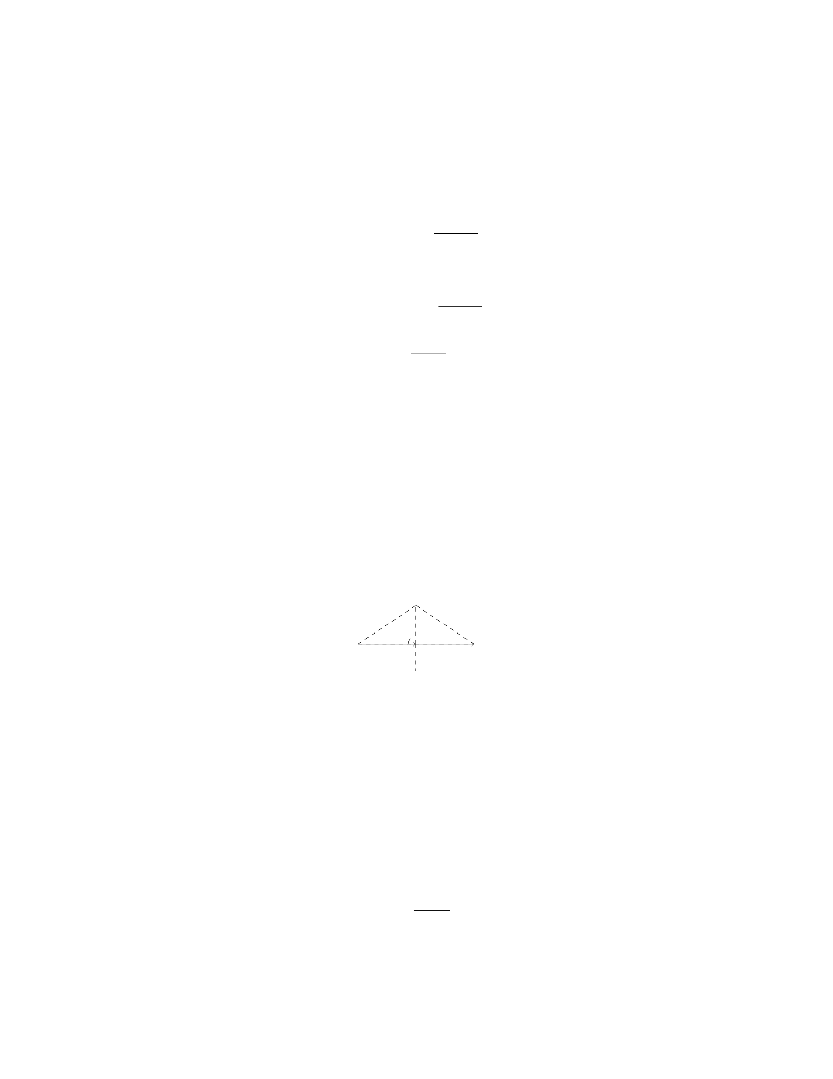
Step 3: The maximum angle from the vertical (θmax) that the rod will make
with the vertical is given by h/L:
θmax = sin−1m2v2
0
2MLg2
Step 4: Finally, we can find the maximum distance dby d=Lsin θmax:
d=Lsin sin−1m2v2
0
2MLg2
d=m2v2
0
2Mg2
Question 12
Question
A uniform beam of length Land mass Mis supported by two cables, one
attached a distance afrom one end and the other attached a distance bfrom
the other end (where a+b=L). The beam is in equilibrium and makes an
angle θwith the horizontal. Find an expression for the tension in each cable in
terms of M,L,a,b, and θ.
Solution
Step 1: Draw a free-body diagram of the beam.
T1T2
Mg
θ
L
θ
Step 2: Write equations for the forces in the x and y directions. In the
x-direction:
T1sin θ−T2sin θ= 0
In the y-direction:
T1cos θ+T2cos θ−Mg = 0
Step 3: Simplify the equations. From the first equation, we have T1=T2.
Substitute this into the second equation to get:
2T1cos θ−Mg = 0
Step 4: Solve for T1.
T1=Mg
2 cos θ
11

Step 5: Substitute in θusing trigonometry.
T1=Mg
2 cos arccos b
L
Step 6: Simplify the expression.
T1=Mg
2b
L=MLg
2b
Step 7: Find the tension in the second cable, T2. Since T1=T2, we have:
T2=MLg
2a
Therefore, the tension in each cable is MLg
2band MLg
2a, respectively.
Question 13
Question
A uniform rod of mass mand length Lis suspended vertically from one end. A
block of mass Mis placed at a distance xfrom the end of the rod, causing the
rod to tilt by an angle θ. Assuming the system is in equilibrium, determine the
expression for θin terms of m,M,L,x, and acceleration due to gravity g.
Solution
To solve this problem, we will first define the forces acting on the system and
then analyze the torques about the point of suspension to find the equilibrium
condition.
Step 1: Define the forces The forces acting on the system are the gravi-
tational forces on the rod, block, and the tension in the rod. Let’s denote: - T
as the tension in the rod, - Fg,rod as the gravitational force on the rod, - Fg,block
as the gravitational force on the block.
Step 2: Analyze the torques Taking moments about the point of sus-
pension (the end of the rod), the torques must sum to zero to be in equilibrium.
The torque from the tension Tdoes not apply any torque about this point since
its line of action passes through the point. The torques from the gravitational
forces are: - Torque from the rod: τrod =−L
2sin(θ)Fg,rod - Torque from the
block: τblock =−xcos(θ)Fg,block
Step 3: Write the equilibrium condition The net torque about the
point of suspension must be zero for equilibrium:
−L
2sin(θ)Fg,rod −xcos(θ)Fg,block = 0
12
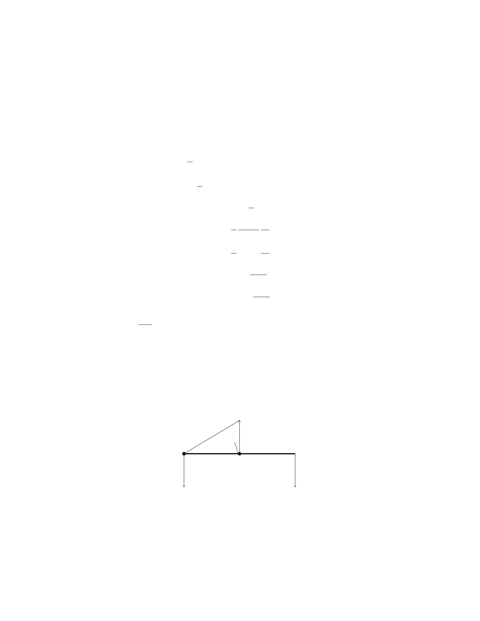
Step 4: Express the gravitational forces in terms of masses and
acceleration due to gravity The gravitational forces can be expressed as:
Fg,rod =m·g Fg,block =M·g
Step 5: Solve for θSubstitute the expressions for gravitational forces into
the equilibrium condition and solve for θ:
−L
2sin(θ)m·g−xcos(θ)M·g= 0
−L
2sin(θ)m−xcos(θ)M= 0
xcos(θ)M=−L
2sin(θ)m
x=−L
2
sin(θ)
cos(θ)
m
M
x=−L
2tan(θ)m
M
tan(θ) = −2xM
Lm
θ= arctan −2xM
Lm
Therefore, the expression for θin terms of m,M,L,x, and gis θ=
arctan −2xM
Lm .
Question 14
Question
A uniform beam of length Land mass Mis supported by two ropes attached
at points Aand B, as shown in the diagram below. The beam makes an angle
of θwith the horizontal. Determine the tension in each rope.
BA
TATB
θ
Mg
Assume the beam is weightless and the tension due to the ropes at points A
and Bact along the length of the beam.
13

Solution
Step 1: First, draw the free-body diagram of the beam.
Step 2: Resolve the forces into their x and y components. Let’s choose the
x-axis to be parallel to the beam and the y-axis to be perpendicular to the beam.
Step 3: Consider the forces acting on the beam in the y-direction. The
sum of forces in the y-direction must be zero since the beam is in equilibrium.
Therefore, we have:
TAcos(θ) + TBcos(θ)−Mg = 0
Step 4: Now consider the forces acting on the beam in the x-direction. The
x-components of the tensions TAand TBmust balance each other. Therefore,
we have:
TAsin(θ) = TBsin(θ)
Step 5: Solve the equations obtained in steps 3 and 4 to find the tensions
TAand TB. From the x-direction equation in Step 4, we have:
TB=TA
Step 6: Substitute TB=TAinto the y-direction equation in Step 3 to find
the value of tension TA:
TAcos(θ) + TAcos(θ)−Mg = 0
2TAcos(θ) = Mg
TA=Mg
2 cos(θ)
Step 7: Therefore, the tension in each rope is Mg
2 cos(θ).
Question 15
Question
A uniform rod of length Land mass Mis hanging vertically with one end
attached to a fixed point and the other end free. A bullet with mass mand
velocity vis fired horizontally and gets embedded in the free end of the rod.
Find the maximum angle the rod can swing from the vertical.
Solution
1. Let’s denote the angle the rod makes with the vertical as θ. We can find the
velocity of the bullet-rod system just after the collision by using conservation
of momentum in the horizontal direction:
M·0=(M+m)·vfinal cos θ
14

vfinal cos θ= 0
vfinal = 0
2. We can also write the conservation of energy equation for the system at
the maximum angle θmax:
Mgh =1
2(M+m)(vfinal)2+Iω2
where his the height at the maximum angle, I=1
3ML2is the moment of
inertia of the rod about its end, and ωis the angular velocity at that angle.
3. Since vfinal = 0, the equation simplifies to:
Mgh =1
2Iω2
4. The gravitational force provides the centripetal force at the maximum
angle:
Mg cos θmax =M+m
2ω2Lsin θmax
5. Substituting ω=vfinal
L= 0, we get:
Mg cos θmax = 0
cos θmax = 0
θmax =π
2
Therefore, the maximum angle the rod can swing from the vertical is π
2
radians or 90 degrees.
Question 16
Question
A uniform rod of length Land mass Mis supported by a pivot at one end.
A block of mass mis attached to the other end of the rod. The system is
in rotational equilibrium when the rod makes an angle θwith the vertical.
Calculate the tension in the rod at this angle.
Solution
To find the tension in the rod at angle θ, we can analyze the torques acting on
the system.
Step 1: Draw a free-body diagram and establish the forces acting on the
system.
15

–The forces acting on the system are the tension in the rod (T), the
force of gravity on the rod (M g), and the force of gravity on the block
(mg).
–The torque due to the tension Tand the forces of gravity must sum
to zero for the system to be in rotational equilibrium.
Step 2: Write the torque equilibrium equation. The torque equilibrium
equation is given by:
Xτ= 0
where the torques are calculated about the pivot point. Torques causing
a clockwise rotation are taken as negative, while those causing a counter-
clockwise rotation are taken as positive.
Step 3: Calculate the torques. The torques in the system are:
–Torque due to tension T: It acts at a distance Lfrom the pivot point
in the counterclockwise direction, so its torque is +T·Lsin(θ).
–Torque due to the block’s weight mg: It acts at a distance Lcos(θ)
from the pivot point in the clockwise direction, so its torque is −mg ·
Lcos(θ).
–Torque due to the rod’s weight Mg: It acts at a distance L/2 from
the pivot point in the clockwise direction, so its torque is −Mg ·L/2.
Step 4: Set up the torque equilibrium equation.
Xτ=T·Lsin(θ)−mg ·Lcos(θ)−Mg ·L/2 = 0
Step 5: Solve for the tension T.
T·Lsin(θ) = mg ·Lcos(θ) + Mg ·L/2
T=mg ·Lcos(θ) + Mg ·L/2
Lsin(θ)
T=mg cos(θ) + Mg/2
sin(θ)
Question 17
Question
A uniform beam of length Land mass mis supported by a pivot at one end and
a cable connected to the ceiling at the other end. The beam makes an angle of
θwith the ceiling and is in rotational equilibrium. If the tension in the cable is
T, express the tension in terms of m,g,L, and θ.
16
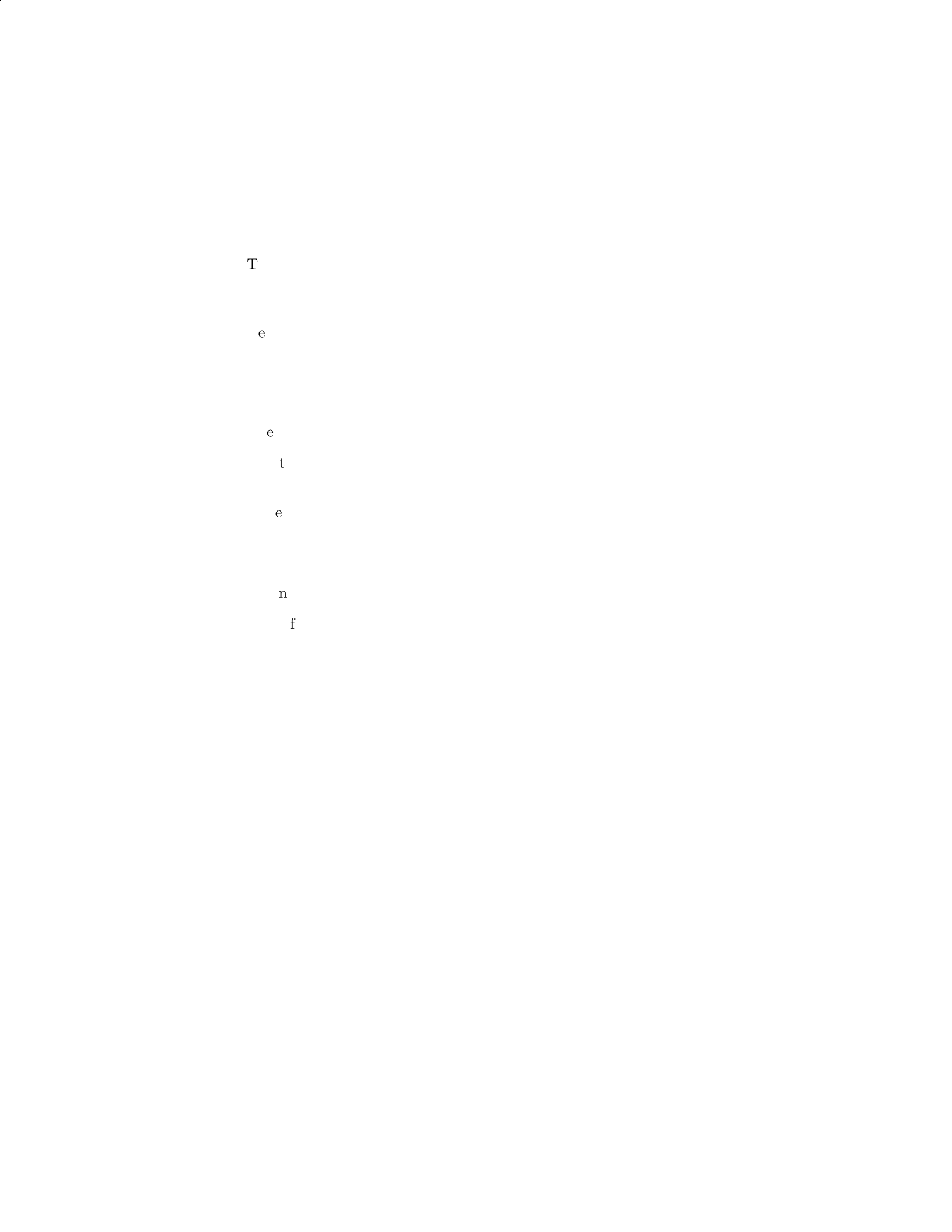
Solution
Step 1: Draw the free-body diagram of the beam.
There are two forces acting on the beam: the gravitational force mg acting
downward at the center of mass and the tension Tacting upwards at an
angle θwith the vertical.
Resolve the tension force into vertical and horizontal components. The
vertical component is Tcos(θ) and the horizontal component is Tsin(θ).
Step 2: Write the torque equation using the pivot point at one end of the
beam.
The torque due to the tension force about the pivot point is τT= (L/2)(Tcos(θ)).
The torque due to the gravitational force about the pivot point is τmg =
−(L/2)(mg sin(θ)).
Since the beam is in rotational equilibrium, the sum of the torques must
be zero: τT+τmg = 0.
Step 3: Solve for the tension T.
Setting τT+τmg = 0 gives (L/2)(Tcos(θ)) −(L/2)(mg sin(θ)) = 0.
Simplifying the equation gives T=mg tan(θ).
Therefore, the tension in the cable in terms of m,g,L, and θis T=
mg tan(θ).
Question 18
Question
A uniform beam of length Land mass M, supported by a cable, is in equilibrium
at an angle θas shown below. The beam has a mass mhanging from one end.
Find the tension in the cable.
17
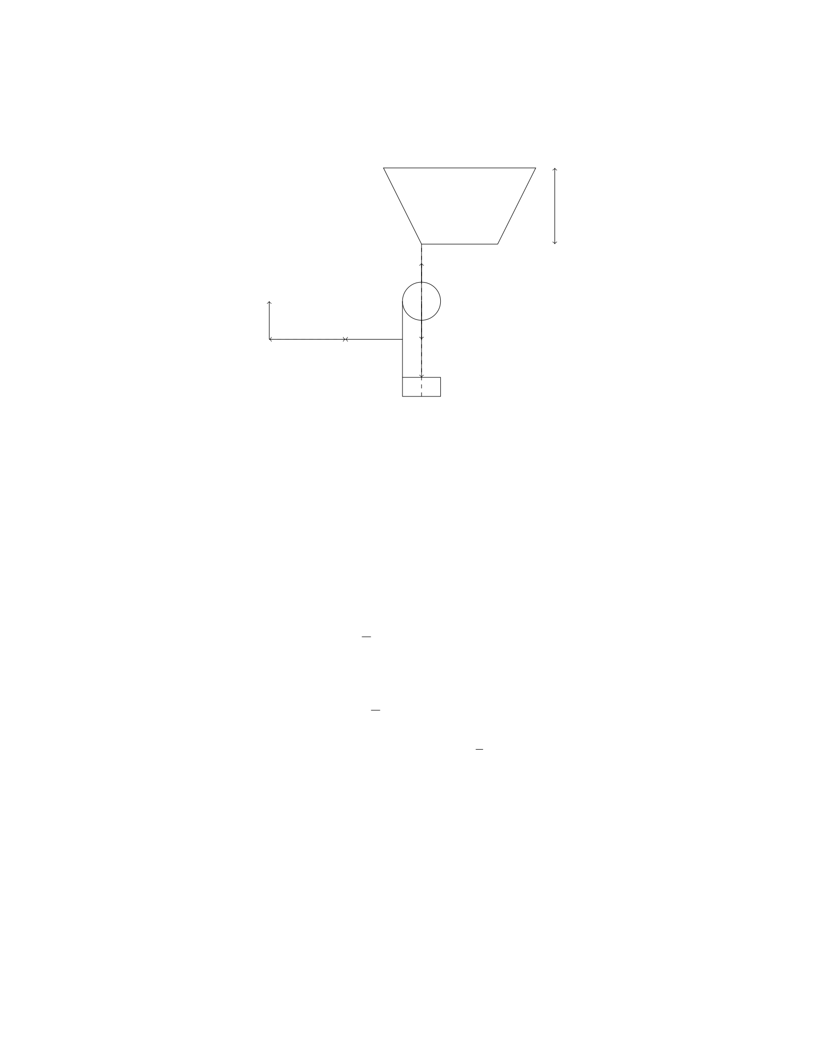
L
m
M
T
x
θ
Solution
To find the tension in the cable, we will first calculate the torque exerted by the
forces around the pivot point O.
Step 1: Set up the torques equation The torques must sum to zero in
order for the beam to be in equilibrium. The torques are calculated about the
pivot point O. Let’s consider the forces that produce a torque:
- The force Tat a distance xfrom the pivot point produces a counterclock-
wise torque: T x. - The force mg at the center of mass (located at L/2 from
O) produces a clockwise torque: mg(L/2) sin(θ). - The force Mg at the far end
(located at Lfrom O) produces a clockwise torque: MgL sin(θ).
Since the beam is in equilibrium, the torques sum to zero:
T x −mg L
2sin(θ)−MgL sin(θ)=0
Step 2: Solve for the tension TSolving for the tension T, we get:
T=mg L
2sin(θ)+MgL sin(θ)
Therefore, the tension in the cable is T=mg L
2sin(θ)+MgL sin(θ).
Question 19
Question
A uniform rod of length Land mass Mis hinged at one end. A force Fis
applied horizontally at the other end (away from the hinge) such that the rod
makes an angle θwith the horizontal. Calculate the magnitude and direction
of the force Fneeded to keep the rod in equilibrium.
18
Solution
Step 1: Draw a free-body diagram of the rod.
Force Magnitude
Tension (T)Lcos(θ)F
Weight (Mg)Mg
Normal force (N)N
Step 2: Write the equations of equilibrium in the horizontal and vertical
directions: XFhorizontal = 0 : T=F
XFvertical =0:N=Mg
Step 3: Write the torque equation with respect to the hinge point:
τ= 0
T(Lsin(θ)) −Mg(L
2cos(θ)) = 0
Lcos(θ)F(Lsin(θ)) −Mg(L
2cos(θ)) = 0
Step 4: Solve for Ffrom the torque equation:
F L sin(θ) = MgL
2
F=Mg
2csc(θ)
Therefore, the magnitude of the force Fneeded to keep the rod in equilibrium
is Mg
2csc(θ). The direction of the force is opposite to the direction of the force
applied initially.
Question 20
Question
A uniform beam of length Land mass Mis supported by a vertical cable
attached at its midpoint. A box of mass mis placed at the end of the beam. If
the tension in the cable is equal to half the weight of the beam, determine the
distance of the box from the end of the beam for the system to be in equilibrium.
19

Solution
Step 1: Draw a free body diagram of the system. Let Tbe the tension in the
cable, Wbe the weight of the beam, M g be the downward force due to gravity
acting on the beam, mbe the mass of the box, and mg be the downward force
due to gravity acting on the box. The distance of the box from the end of the
beam is denoted as x. The forces acting on the beam are the tension T, weight
W, and the pivot force. The forces acting on the box are the tension Tand its
weight mg. The pivot force acts at the midpoint of the beam.
Step 2: Write the equations for the equilibrium of the system. For transla-
tional equilibrium of the beam along the horizontal axis: Sum of forces in the
horizontal direction = 0 T=1
2W T =1
2Mg
For rotational equilibrium of the system: Sum of torques about the pivot
point = 0 T·L
2=mg ·(L−x)
Step 3: Solve the equations simultaneously. We already know T=1
2Mg.
Substitute the values into the equation for the torque: 1
2Mg ·L
2=mg ·(L−x)
(1
2Mg)·L
2=mg ·L−mg ·x1
4MgL =mgL −mgx
Step 4: Solve for x.mgx =mgL −1
4MgL x =L−1
4
M
mL
Therefore, the distance of the box from the end of the beam for the system
to be in equilibrium is L−1
4
M
mL.
Question 21
Question
A metal wire with length Land cross-sectional area Ais stretched by a force
F. The Young’s modulus of the material is Y. Determine the maximum length
that the wire can be stretched before reaching its elastic limit, assuming it is
initially at equilibrium.
Solution
Step 1: Let’s consider the equilibrium of forces on the wire. At the elastic limit,
the force Fbalances the force due to the stretching of the wire.
Step 2: The force due to the stretching can be calculated using Hooke’s Law,
F=k·∆L, where kis the spring constant (related to the Young’s modulus)
and ∆Lis the change in length of the wire.
Step 3: The change in length ∆Lcan be expressed as F
A·Y, where Ais the
cross-sectional area of the wire and Yis the Young’s modulus.
Step 4: Setting F=k·F
A·Yand solving for k, we find k=A·Y
L.
Step 5: Now, we can find the maximum length the wire can be stretched
before reaching its elastic limit. At this point, the force Fequals the yield
strength of the material.
Step 6: The yield strength is the stress at which the material undergoes
permanent deformation. It can be calculated as F
A.
20

Step 7: Setting F
A=k·∆L, we find ∆L=F L
AY .
Step 8: Therefore, the maximum length the wire can be stretched before
reaching its elastic limit is F L
AY .
Question 22
Question
A block of mass mhangs from a spring scale attached to the ceiling of an
elevator. When the elevator is accelerating upward at aup, the scale reads N1.
When the elevator is accelerating downward at adown, the scale reads N2. Find
the spring constant of the scale.
Solution
Step 1: Identify the forces acting on the block when the elevator is moving
upward: The forces acting on the block are its weight mg, the tension in the
spring scale N1, and the normal force due to the elevator floor N. Applying
Newton’s second law in the vertical direction, we have:
N1−mg =maup
Step 2: Identify the forces acting on the block when the elevator is moving
downward: The forces acting on the block are its weight mg, the tension in the
spring scale N2, and the normal force due to the elevator floor N. Applying
Newton’s second law in the vertical direction, we have:
N−N2=madown
Step 3: Since the block is in equilibrium when stationary, the normal force N
is equal to the weight mg. Thus, we get:
N=mg
Step 4: Substitute N=mg in the equations from Step 1 and Step 2: For the
upward acceleration:
N1−mg =maup
For the downward acceleration:
mg −N2=madown
Step 5: Since N1and N2are the readings of the spring scale, they can be related
to the spring constant kby N1=kx and N2=−kx, where xis the displacement
of the block. Step 6: Substitute N1=kx and N2=−kx into the equations
from Step 4: For the upward acceleration:
kx −mg =maup
21

For the downward acceleration:
mg +kx =madown
Step 7: Adding the two equations from Step 6, we get:
2kx =m(aup +adown)
Step 8: Rearrange the equation to solve for the spring constant k:
k=m(aup +adown)
2x
Question 23
Question
A 2.5 m long uniform beam of mass 10 kg is supported at each end with a 80 kg
mass placed 0.8 m from the left end. What is the tension in the left support?
(Assume g = 9.81 m/s2)
Solution
Step 1: Draw a free-body diagram of the beam. There are three forces acting
on the beam: the weight of the beam itself, the weight on the left end, and the
weight on the right end. Call the tension in the left support TLand the tension
in the right support TR. Step 2: Write the equilibrium condition for forces in
the vertical direction. The sum of all forces in vertical direction is zero. Step 3:
Express weight of the beam and masses in terms of their masses and acceleration
due to gravity. Step 4: Write the torque equilibrium condition. The sum of all
torques acting on the beam must be zero. Step 5: Express torque due to the
weight of the beam and masses. Step 6: Solve the equations simultaneously to
find TL.
TL=1
2(Mb+M1+M2)g
Plugging in the given values,
TL=1
2(10 + 80 + 80) ×9.81
TL= 245.25 N
Therefore, the tension in the left support is 245.25 N.
22
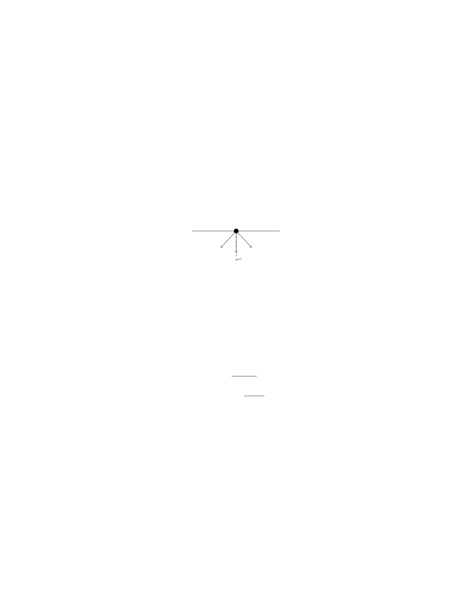
Question 24
Question
A uniform rectangular beam of length Land mass Mis supported by two ropes
attached to the ends of the beam. If the angle between each rope and the beam
is θ, find the tension in each rope in terms of M,g,L, and θ.
Solution
Let’s denote the tension in each rope as T. To start, we need to draw a free
body diagram of the beam. There are three forces acting on the beam: the
gravitational force Mg acting downward, and the two vertical components of
the tensions in the ropes.
Mg
T T
θ
Note that the forces must add up to zero in both the horizontal and vertical
directions since the beam is in equilibrium.
Step 1: Resolve Tinto horizontal and vertical components. The vertical
component of each tension Tis Tcos(θ).
Step 2: Write the equation for the vertical forces. Summing the forces in
the vertical direction:
2Tcos(θ) = Mg
Step 3: Solve for the tension in each rope. Dividing both sides by 2, we
get:
T=Mg
2 cos(θ)
Therefore, the tension in each rope is Mg
2 cos(θ).
Question 25
Question
A 2.00 m long steel wire with a radius of 1.00 mm is stretched to a tension of
100 N. If Young’s modulus for steel is 2.00×10¹¹ N/m2, calculate the maximum
energy the wire can store elastically before it permanently deforms.
23

Solution
Step 1: Calculate the cross-sectional area of the wire. Given the radius of the
wire, r= 1.00 mm = 1.00 ×10⁻³m. The cross-sectional area, A, of the wire is
given by:
A=πr2
A=π×(1.00 ×10⁻³)2
A=π×1.00 ×10⁻⁶
A= 3.14 ×10⁻⁶m2
Step 2: Calculate the elastic modulus of the wire. Given Young’s modulus,
Y= 2.00 ×10¹¹ N/m2.
Step 3: Calculate the strain in the wire. The strain, ε, in the wire is given
by:
ε=F
A·Y
ε=100
3.14 ×10−6×2.00 ×1011
ε=100
6.28 ×10⁵
ε= 1.59 ×10⁻⁴
Step 4: Calculate the elastic potential energy stored in the wire. The elastic
potential energy, U, stored in the wire is given by:
U=1
2F·ε·L
U=1
2×100 ×1.59 ×10−4×2.00
U= 0.0796 J
Therefore, the maximum energy the wire can store elastically before it per-
manently deforms is 0.0796 J.
Question 26
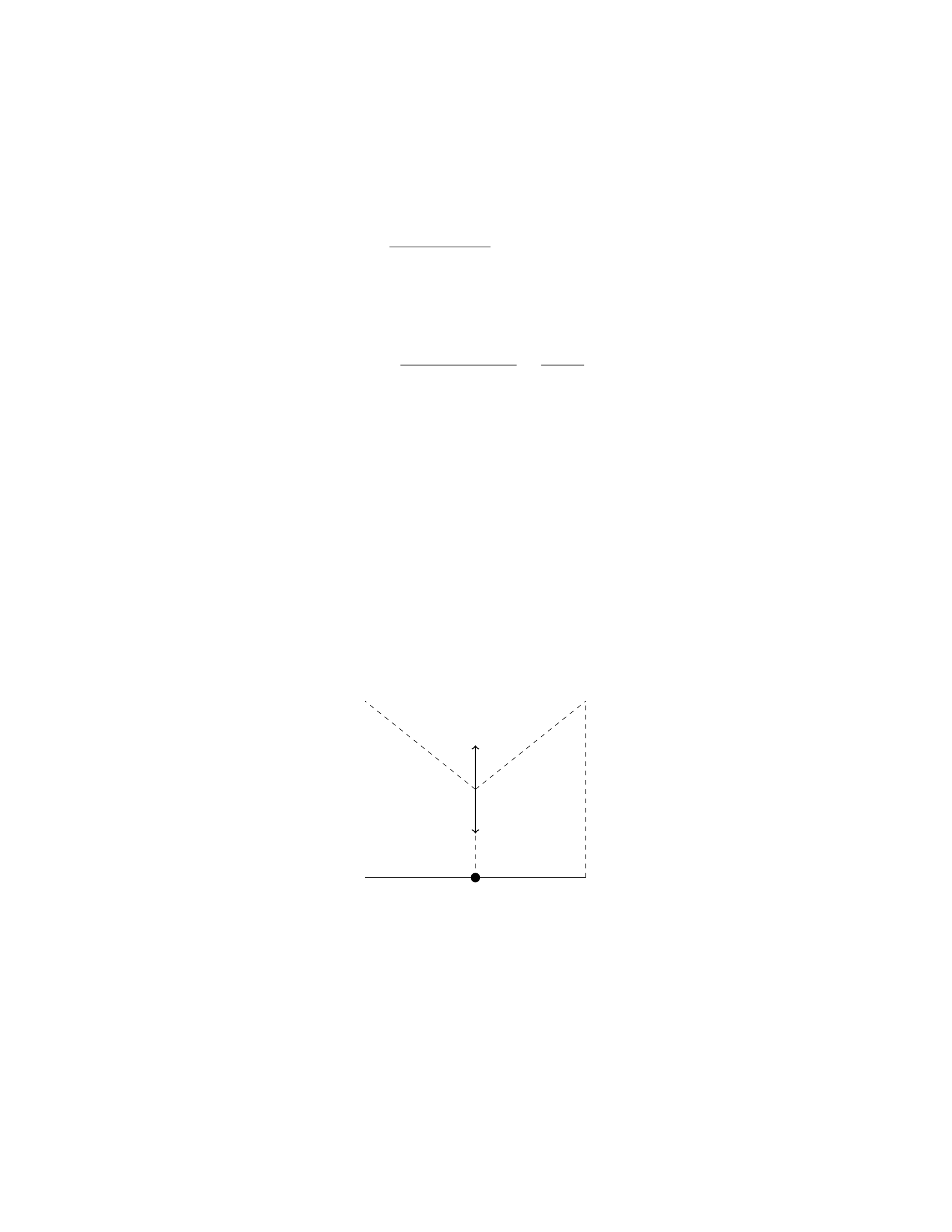
Question
A horizontal plank of mass mand length Lis supported by two ropes attached
to the ends of the plank. The angles that the ropes make with the horizontal
are θ1and θ2, as shown in the figure. If the tension in the rope attached to the
left end of the plank is T1and the tension in the rope attached to the right end
is T2, determine the horizontal and vertical forces on the plank.
equilibrium_diagram.png
24
Solution
Step 1: Draw a free body diagram of the plank.
Forces Directions
T1Up and to the left at angle θ1
T2Up and to the right at angle θ2
mg Downward
NUpward
Step 2: Break down the forces into their components.
The forces T1and T2can be broken down into their x- and y-components.
Resolving T1into components, we get:
T1x=T1cos θ1and T1y=T1sin θ1
Similarly, resolving T2into components, we get:
T2x=T2cos θ2and T2y=T2sin θ2
Step 3: Write down the force equations in the x and y directions.
In the x-direction, the forces are balanced:
T1x=T2x
In the y-direction, the forces are balanced as well:
N−mg =T1y+T2y
Step 4: Solve for the horizontal and vertical forces on the plank.
From the x-direction equation, we have:
T1cos θ1=T2cos θ2
From the y-direction equation, we have:
N−mg =T1sin θ1+T2sin θ2
Therefore, the horizontal force on the plank is T1cos θ1=T2cos θ2and the
vertical force on the plank is N=mg +T1sin θ1+T2sin θ2.
Question 27
Question
A uniform bridge has a length of Land a mass M. A car of mass mis parked
at a distance xfrom one end of the bridge. The car exerts a downward force
on the bridge due to its weight. What is the force on the bridge at a distance y
from the end where the car is parked?
25

Solution
Step 1: Let’s first calculate the downward force exerted by the car on the bridge.
This force is equal to the weight of the car, so it can be calculated as Fcar =mg.
Step 2: To find the force at a distance yfrom the end where the car is
parked, we need to analyze the forces acting on a small section of the bridge of
length ∆yat that point.
Step 3: The forces acting on this section are the gravitational force (due to
the bridge’s own weight) and the force from the car. The gravitational force on
this section is ∆Fbridge =−Mg
L∆y, where the negative sign indicates that it is
directed upwards.
Step 4: The net force acting on this section is given by PF= ∆Fbridge +
∆Fcar.
Step 5: Applying Newton’s second law for the vertical direction (PF=ma),
we have ∆Fbridge + ∆Fcar =M∆2y
∆t2.
Step 6: Substituting the expressions for ∆Fbridge and ∆Fcar, we get −M g
L∆y+
mg =M∆2y
∆t2.
Step 7: Simplifying, we have −gM
L∆y+mg =M∆2y
∆t2.
Step 8: In the limit as ∆y→0, this becomes a differential equation: −Mg
Ly+
mg =Md2y
dt2.
Step 9: Solving this differential equation with initial conditions, we can find
the force on the bridge at a distance yfrom the end where the car is parked.
Question 28
Question
A steel cable with a diameter of 2.0 cm supports a load of 5000 N. If the cable
stretches 20 cm under this load, what is the Young’s modulus of the steel?
Solution
Step 1: Find the cross-sectional area of the steel cable. The cross-sectional area
of the cable can be calculated using the formula for the area of a circle:
A=πr2
Given that the diameter of the cable is 2.0 cm, the radius ris 1.0 cm or 0.01 m.
Therefore, the cross-sectional area is:
A=π(0.01 m)2= 3.14 ×10⁻⁴m2
Step 2: Calculate the stress on the cable. Stress is defined as the force
applied per unit area. In this case, the stress applied to the cable is given by:
Stress = Force
Area
26
Substitute the given values to find the stress:
Stress = 5000 N
3.14 ×10⁻⁴m2= 1.59 ×10⁷N/m2
Step 3: Use Hooke’s Law to calculate the Young’s modulus. Hooke’s Law
states that the stress is directly proportional to the strain. In this case, the
strain is the elongation of the cable divided by its original length.
Strain = Change in length
Original length =0.20 m
0.20 m = 1
Now, use Hooke’s Law to find the Young’s modulus:
Stress = Young’s modulus ×Strain
1.59 ×10⁷N/m2= Young’s modulus ×1
Therefore, the Young’s modulus of the steel is 1.59 ×10⁷N/m2.
Question 29
Question
A uniform beam of mass mand length Lis supported horizontally by two
vertical strings, as shown in the diagram below. The tension in the first string
is twice the tension in the second string. The beam is in static equilibrium.
Find the tensions T1and T2in the strings.
m
T1
T2
Solution
Step 1: Identify the forces acting on the beam.
The forces acting on the beam are: - The weight of the beam acting down-
wards at its center, mg. - The tension T1in the first string acting upwards at
the center of the beam. - The tension T2in the second string acting upwards
at the center of the beam.
27

Since the beam is in static equilibrium, the net force and net torque acting
on the beam must be zero.
Step 2: Write the equations for equilibrium.
Net Force in the vertical direction: T1+T2−mg = 0
Net Torque about the center of the beam: T2L
2−T1L
2= 0
Step 3: Solve the equations for T1and T2.
From the first equation, we have T1+T2=mg.
Given that T1= 2T2, we can substitute this into the equation above:
2T2+T2=mg
3T2=mg
T2=mg
3
Substitute T2back into T1= 2T2:
T1= 2 mg
3=2mg
3
Therefore, the tensions in the strings are T1=2mg
3and T2=mg
3.
Question 30
Question
A uniform beam of length Land mass Mis supported at an angle θby a light
string attached at the midpoint of the beam. A weight Wis hung at one end of
the beam. If the tension in the string is T, calculate the tension in the string.
beam.png
Solution
Step 1: Draw the free body diagram of the beam.
The forces acting on the beam are the weight Wacting downward, the
tension Tacting upward at an angle θwith respect to the vertical, and the
gravitational force acting downward at the center of mass. The gravitational
force can be split into a component perpendicular to the beam (M g ·L
2) and
a component parallel to the beam (Mg). Let’s denote the length of the beam
from the pivot point to the end with the weight x.
Step 2: Write the torque equation about the left end of the beam.
Summing up the torques about the left end of the beam, we have:
W·L
2·sin(θ)−T·L
2·cos(θ)=0
28

Step 3: Write the force balance equations in the xand ydirections.
In the vertical direction, we have:
T·sin(θ) = M·g
In the horizontal direction, we have:
T·cos(θ) = W
Step 4: Solve the system of equations.
From the force balance equations, we have:
T=M·g
sin(θ)
And from the torque equation, we have:
W=M·g
tan(θ)
Therefore, the tension in the string is M·g
sin(θ).
Question 31
Question
A uniform iron rod of length 1.5 m and mass 4.0 kg is suspended horizontally
by two vertical steel wires of equal length. The rod is heated to 150
°
C, causing
it to expand. If the coefficient of linear expansion for steel is 1.20 ×10⁻⁵
°
C−1
and the coefficient of linear expansion for iron is 6.50×10⁻⁶
°
C−1, by how much
does the tension in each wire change due to the heating of the rod?
Solution
Step 1: We will first find the change in length of the iron rod when heated.
Given that the coefficient of linear expansion for iron is αiron = 6.50 ×
10−6
°
C−1, the initial length of the iron rod is Liron = 1.5 m, and the change in
temperature is ∆T= 150C.
The change in length ∆Lof the rod can be calculated using the formula:
∆Liron =αiron ·Liron ·∆T
Substitute the given values to find ∆Liron:
∆Liron = (6.50 ×10⁻⁶
°
C−1)·(1.5 m) ·(150C)
∆Liron = 0.0014625 m = 1.463 mm
29

Step 2: Next, we need to determine the change in tension in the steel wires
due to the expansion of the iron rod.
Since the steel wires are of equal length and the iron rod is suspended by
them, the change in length of each steel wire will be half of the change in length
of the iron rod.
Therefore, the change in length of each steel wire can be calculated as:
∆Lsteel =1
2·∆Liron =1
2·0.0014625 m = 0.00073125 m
Step 3: Now we will calculate the change in tension in each steel wire.
Let Tbe the initial tension in each steel wire before heating.
The change in tension ∆Tin each steel wire can be calculated using Hooke’s
Law:
∆T=k·∆Lsteel
where kis the spring constant for each steel wire.
Since the steel wires are under tension, the change in tension will be negative.
Therefore, the change in tension ∆Twill point upward due to the expansion of
the iron rod.
Thus, the magnitude of the change in tension ∆Tin each steel wire will be:
|∆T|=k·∆Lsteel
Step 4: Since both steel wires are identical and experience the same change
in tension, the total change in tension due to the heating of the rod will be
2|∆T|.
Thus, the total change in tension in the steel wires will be:
2|∆T|= 2k∆Lsteel
Question 32
Question
A uniform bridge, of total length L, rests on two supports that are each a
distance dfrom the ends of the bridge. A car of mass mis parked in the middle
of the bridge. If the bridge has a mass M, determine the reaction forces on each
support when it is in equilibrium.
Solution
Let’s denote R1as the reaction force at the left support and R2as the reaction
force at the right support.
Step 1: Identify the forces acting on the bridge. The forces acting on the
bridge include the weight of the bridge itself (Mg), the weight of the car (mg),
the force R1at the left support, and the force R2at the right support.
30

Step 2: Write down the equilibrium equations. In the vertical direction,
the sum of the forces must be zero:
R1+R2−Mg −mg = 0
In the torques equation, we can take the torques about the left support:
R2·(L−d)−Mg ·L
2−mg ·L
2= 0
Step 3: Solve the equilibrium equations. From the vertical equilibrium
equation:
R1+R2=Mg +mg
Substitute R1=Mg +mg −R2into the torque equation:
R2·(L−d)−Mg ·L
2−mg ·L
2= 0
Simplify and solve for R2:
R2·(L−d) = (M+m)Lg
2
R2=(M+m)g·L
2(L−d)
Step 4: Find R1. Substitute the value of R2back into the equation R1+
R2=Mg +mg:
R1=Mg +mg −R2
Now you can calculate the numerical values for R1and R2given the masses
M,m, the length of the bridge L, and the distance of the supports d.
Question 33
Question
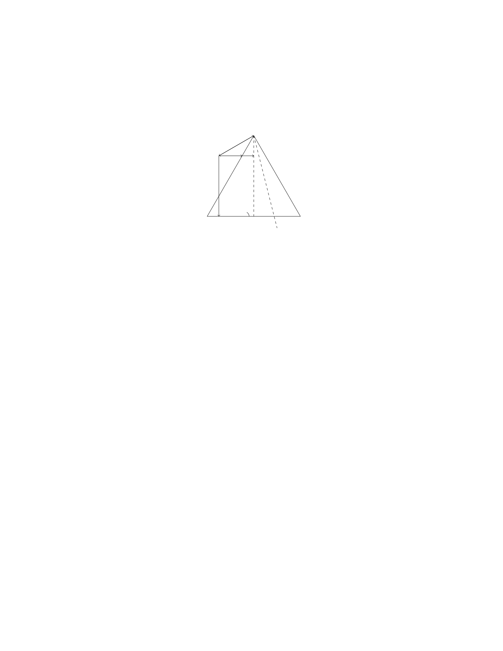
A 5 kg block is resting on an inclined plane that makes an angle of 30◦with
the horizontal. The coefficient of static friction between the block and the plane
is 0.4. What is the maximum angle at which the block can sit without sliding
down the incline?
Solution
Step 1: Draw a free-body diagram of the block on the inclined plane. Step 2:
Break the gravitational force into components parallel and perpendicular to the
incline. Step 3: Write the force balance equations for the block in the direction
perpendicular to the incline. Step 4: Write down the force balance equations for
the block in the direction parallel to the incline. Step 5: Set up the inequality
for static equilibrium in the direction parallel to the incline to find the maximum
angle. Step 6: Solve for the maximum angle at which the block can sit without
sliding down the incline.
31
Solution
Step 1: Draw a free-body diagram of the block on the inclined plane.
N
mg
ffriction
fnormal
θ
Step 2: The gravitational force mg can be resolved into components parallel
and perpendicular to the incline:
mg sin(θ)
mg cos(θ)
Step 3: Write the force balance equations for the block in the direction
perpendicular to the incline.
N−mg cos(θ)=0
N=mg cos(θ)
Step 4: Write down the force balance equations for the block in the direction
parallel to the incline.
ffriction −mg sin(θ) = 0
ffriction =mg sin(θ)
Step 5: Set up the inequality for static equilibrium in the direction parallel
to the incline to find the maximum angle:
ffriction ≤µs·fnormal
mg sin(θ)≤µs·mg cos(θ)
sin(θ)≤µs·cos(θ)
Step 6: Solve for the maximum angle at which the block can sit without
sliding down the incline:
tan(θ)≤µs
θ≤arctan(µs)
θ≤arctan(0.4) ≈21.8◦
Therefore, the maximum angle at which the block can sit without sliding
down the incline is approximately 21.8◦.
32
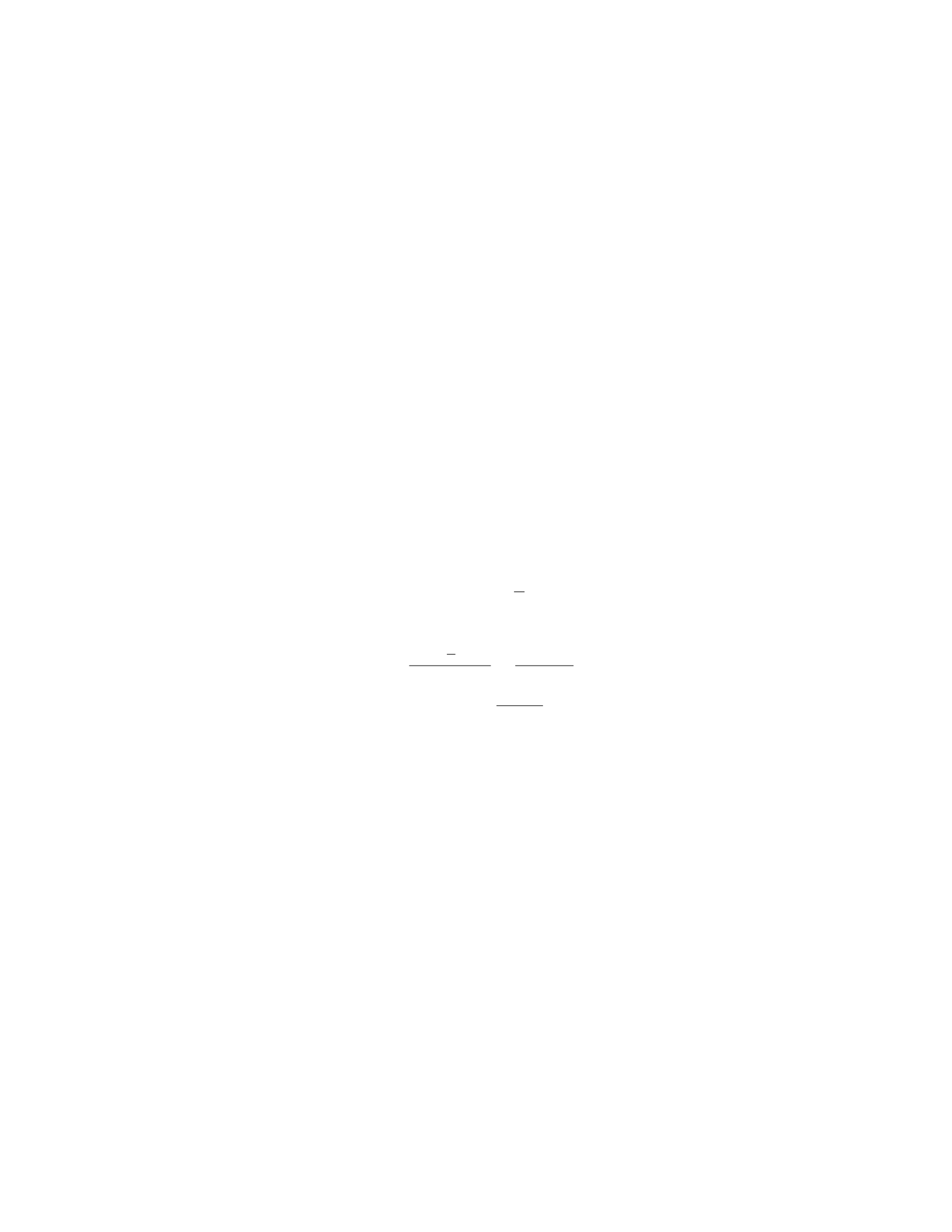
Question 34
Question
A uniform, horizontal beam of length Land mass Mis supported by a cable
attached to its end. The beam makes an angle θwith the horizontal and the
tension in the cable is T. Determine the tension in the cable in terms of L,M,
θ, and g.
Solution
Step 1: We will begin by drawing a free-body diagram of the beam. The
forces acting on the beam are the tension Tin the cable, the gravitational force
Mg acting at the center of mass, and the normal force Nacting at the pivot
point. Step 2: Resolve the gravitational force into components. The vertical
component balances the normal force, and the horizontal component provides
the net torque about the pivot point: Mg cos θ. Step 3: The torque produced
by the tension in the cable is T·Lsin θ(clockwise). There is no torque due to
the normal force as it acts at the pivot point. Step 4: The beam is in rotational
equilibrium, so the net torque about the pivot point is zero. Set up the torque
equation:
T·Lsin θ=Mg ·L
2cos θ
Step 5: Solve the equation for Tto find the tension in the cable:
T=Mg ·L
2cos θ
Lsin θ=Mg cos θ
2 sin θ
Therefore, the tension in the cable is T=Mg cos θ
2 sin θ.
Question 35
Question
A uniform wooden beam of length Land weight Wis supported by a rope at
each end. The beam hangs vertically and is pulled down until it is horizontal.
Determine the tension in each rope when the beam makes an angle θwith the
vertical. Assume the beam has mass M, and its center of mass is located at its
center.
Solution
Step 1: Draw a free-body diagram for the beam in equilibrium. Let’s consider
the forces acting on the beam when it is at an angle θwith the vertical. The
forces acting on the beam are the weight Wacting at the center of mass down-
ward, the tension forces T1and T2acting at each end of the beam, and the
normal force acting perpendicular to the beam at its center.
33

Step 2: Resolve the forces into components. The weight Wcan be re-
solved into two components: Wx=−Wsin(θ) parallel to the beam and Wy=
−Wcos(θ) perpendicular to the beam. The tension forces T1and T2each have
components T1x=T1sin(θ) and T1y=T1cos(θ), and T2x=T2sin(θ) and
T2y=T2cos(θ), respectively.
Step 3: Set up equations for equilibrium in the vertical and horizontal di-
rections. In the vertical direction, the sum of forces equals zero:
T1y+T2y−Wy= 0
T1cos(θ) + T2cos(θ)−Wcos(θ) = 0
Similarly, in the horizontal direction:
T1x+T2x= 0
T1sin(θ) + T2sin(θ)=0
Step 4: Find the tensions in each rope. Since the beam is in equilibrium,
the sum of the torques about any point must be zero. Taking torques about the
center of the beam and using the torque equation:
τ= Force ×Lever Arm
T1·L
2sin(θ)−T2·L
2sin(θ) = 0
T1−T2= 0
T1=T2
Step 5: Substitute T1=T2into the vertical equilibrium equation.
T1cos(θ) + T1cos(θ)−Wcos(θ)=0
2T1cos(θ) = Wcos(θ)
T1=W
2
Therefore, the tension in each rope when the beam makes an angle θwith
the vertical is W
2.
34

Question 5
Question
A block of mass mis hanging from a vertical spring with spring constant k.
When the block is in equilibrium, the spring is stretched by a distance x. If the
block is pulled a small distance dx below the equilibrium position and released,
find the period of its resulting oscillation.
Solution
Step 1: Find the force constant due to gravity when the block is displaced by
dx. The force constant due to gravity is given by F=mg, where mis the mass
of the block and gis the acceleration due to gravity. Since the block is displaced
by dx below equilibrium, the restoring force due to gravity is mg +k(dx −x).
Step 2: Apply Hooke’s Law to find the acceleration at displacement dx.
Hooke’s Law states that the force exerted by a spring is proportional to the
displacement. Therefore, k(dx −x) is the force exerted by the spring. Using
Newton’s second law, F=ma, we have:
mg +k(dx −x) = ma
Solving for a, we get:
a=g+k
m(dx −x)
Step 3: Find the time period of oscillation. Since the motion is simple
harmonic, we know that a=−ω2x, where ωis the angular frequency. From
Step 2, we can substitute the expression for ato obtain the differential equation:
g+k
m(dx −x) = −ω2x
Solving for ω, we have:
ω=rk
m
Step 4: Determine the time period T. The time period of oscillation Tis
related to the angular frequency ωby T=2π
ω. Substituting the value of ωwe
found in Step 3, we get:
T=2π
qk
m
Therefore, the period of oscillation is T= 2πpm
k.
5

Question 6
Question
A uniform beam of mass Mand length Lis supported by a cable attached to
its end. The beam is also supported by a horizontal force at a distance xfrom
the cable, as shown in the diagram below. The beam has a mass mplaced at a
distance L
4from the cable. If the tension in the cable is T, find the tension in
the cable.
[Diagram: a rectangular beam with length Lsupported by a cable at one
end, attached to a horizontal force Fat a distance xfrom the cable. A mass m
is placed at a distance L
4from the cable.]
Solution
Step 1: By considering the torques acting on the beam, we can write the equa-
tion for rotational equilibrium:
Xτ= 0
The torques acting on the beam are due to the forces T,F, and the weight of
the beam Mg acting at the center of mass. Let’s consider the torques about the
left end where the cable is attached.
Step 2: The torque due to the tension Tabout the left end is T·L. The
torque due to the force Fis F·(L−x). The torque due to the weight of the
beam is L
2·Mg. The torque due to the weight mis L
4·mg.
Step 3: Setting up the torque equation, we have:
T·L−F·(L−x)−L
2·Mg −L
4·mg = 0
Step 4: Now, we can isolate the tension Tin the cable from the torque
equation. Rearranging terms, we get:
T=F·L−x
L+Mg
2+mg
4
Step 5: We have expressed the tension in the cable Tin terms of the applied
horizontal force F, the distances xand L
4, as well as the mass of the beam and
the additional mass m. This is our final expression for the tension in the cable.
Question 7
Question
A uniform rod of length Land mass Mis supported horizontally at two points,
a distance aapart. A weight Wis hung a distance bfrom one end of the rod.
Determine the horizontal force Fthat must be applied at the other end of the
rod to keep it in equilibrium.
6

Solution
Step 1: First, we need to draw the free body diagram of the rod and apply
the condition for rotational equilibrium. Let Fbe the horizontal force and R1
and R2be the reaction forces at the supports. The weight of the rod can be
assumed to act at its center of mass, which is at a distance L/2 from each end.
The weight Wacts at a distance bfrom one end. The torques from these three
forces should sum to zero to maintain equilibrium. Step 2: The torque equation
for the rod is: −F·(L−a) + R1·a−W·b= 0. Step 3: Next, we need to
form the force balance equation. The forces in the vertical direction must cancel
out, so R1+R2−W−M·g= 0. Since the rod is in equilibrium, R1=W
and R2=Mg. Step 4: Substituting R1=Wand R2=Mg into the torque
equation, we get −F·(L−a) + W·a−W·b= 0. Step 5: Solving for F, we
find F=W(b−a)
L. Therefore, the horizontal force Fthat must be applied at the
other end of the rod to keep it in equilibrium is W(b−a)
L.
Question 8
Question
A rod of length Land mass Mis pivoted about one end. A force Fis applied
perpendicular to the other end of the rod at a distance dfrom the pivot point.
Find the tension in the rod and the acceleration of the pivot point in terms of
F,L,d, and M.
Solution
Step 1: Draw a free-body diagram of the rod. The forces acting on the rod are
the tension Tin the rod and the force Fapplied at a distance dfrom the pivot.
Step 2: Write the torque equation about the pivot point. The torque due to
the force Fis given by:
τF=F·d
The torque due to the tension Tis given by:
τT=T·L
Since the rod is in equilibrium, the total torque about the pivot point must be
zero, so:
τF=τT
Step 3: Set up and solve the torque equation.
F·d=T·L
Solving for Tgives:
T=F·d
L
7

Step 4: Use Newton’s second law to find the acceleration of the pivot point.
Since the rod is in equilibrium, the net force acting on it is zero. The tension T
and the force Fare the only forces acting in the horizontal direction. Therefore:
T=F
Now, use Newton’s second law for rotation about the pivot point:
T·L=I·α
where Iis the moment of inertia of the rod about the pivot point and αis the
angular acceleration of the rod. Since the rod is pivoted at one end, the moment
of inertia Iis 1
3ML2.
Step 5: Find the angular acceleration of the rod. Substitute T=Fand
I=1
3ML2into the equation:
F·L=1
3ML2·α
Solving for αgives:
α=3F
ML
Step 6: Find the acceleration of the pivot point. The acceleration of the
pivot point is given by:
a=α·L
2
Substitute α=3F
ML into the equation:
a=3F
ML ·L
2=3F
2M
Therefore, the tension in the rod is T=F·d
Land the acceleration of the pivot
point is a=3F
2M.
Question 9
Question
A uniform beam of length Land mass Mis placed on two supports, one at each
end. A weight Wis placed adistance from one end of the beam. If the beam
makes an angle θwith the horizontal, determine the normal forces exerted by
the supports on the beam.
Solution
To solve this problem, we will analyze the forces acting on the beam and the
torques about the point where one of the supports is placed.
Step 1: Draw a Free Body Diagram (FBD) of the Beam
8

The forces acting on the beam are the weight Mg acting at the center
of the beam, the weight Wacting at a distance afrom the center of the
beam, the normal force N1from the left support, and the normal force N2
from the right support.
The beam makes an angle θwith the horizontal.
Step 2: Analyze Forces in the Vertical Direction Since the beam is
in equilibrium, the sum of the vertical forces must be zero:
N1+N2=Mg +W
Step 3: Analyze Torques about the Left Support The torque due
to the weight Mg about the left support is counterclockwise and given by
MgL/2·sin(θ). The torque due to the weight Wabout the left support is
counterclockwise and given by W a ·sin(θ). The torque due to the normal force
N2about the left support is clockwise and given by N2·L·cos(θ).
Setting up the torque equation:
MgL/2·sin(θ) + W a ·sin(θ) = N2·L·cos(θ)
Step 4: Solve for N1and N2From the equation of the sum of vertical
forces and the torque equation, we have a system of two equations with two
unknowns:
N1+N2=Mg +W
MgL/2·sin(θ) + W a ·sin(θ) = N2·L·cos(θ)
Solving this system yields the values of N1and N2.
Question 10
Question
A uniform rod of length Land mass Mis hanging vertically from a fixed point
on one end. A block of mass mis attached to the other end of the rod. The
rod makes an angle θwith the vertical. Given that the tension in the rod is T,
determine the value of θin terms of M,m,L, and g.
Solution
Step 1: Draw a free-body diagram of the rod and the block. Consider the
forces acting on both objects. The tension Tis in the rod, while gravity acts on
both the rod and the block. Decompose the gravitational force into components
parallel and perpendicular to the rod.
Step 2: Now we can write the equilibrium equations for the rod and the
block. For the rod: XFx= 0 =⇒Tsin θ= 0
9

XFy= 0 =⇒Tcos θ=Mg
For the block: XFy= 0 =⇒T=mg
Step 3: From the equation for the rod in the ˆydirection, we can substitute
T=mg to eliminate T:
mg cos θ=Mg
Solving for θgives:
cos θ=M
m
Step 4: Finally, finding θ, we have:
θ= cos−1M
m
Therefore, the angle θin terms of M,m,L, and gis θ= cos−1M
m.
Question 11
Question
A uniform rod of length Land mass Mis hanging vertically from one end. A
ball of mass mstrikes the bottom end of the rod with a speed v. The collision is
partially inelastic and the ball sticks to the rod. What is the maximum distance
the ball and rod will swing from the vertical?
Solution
Step 1: First we need to find the velocity of the center of mass of the system
just after the collision. Let vcm be the velocity of the center of mass, and v0
be the velocity of the ball just before the collision. The total momentum of the
system is conserved, thus we have:
Mvcm =mv0
vcm =mv0
M
Step 2: Now, we calculate the height to which the center of mass rises. At
its highest point, all the kinetic energy of the system is converted into potential
energy. The initial kinetic energy of the system is due to the horizontal motion
of the ball just before the collision. Thus, we have:
1
2Mv2
cm =Mgh
h=v2
cm
2g=m2v2
0
2Mg2
10
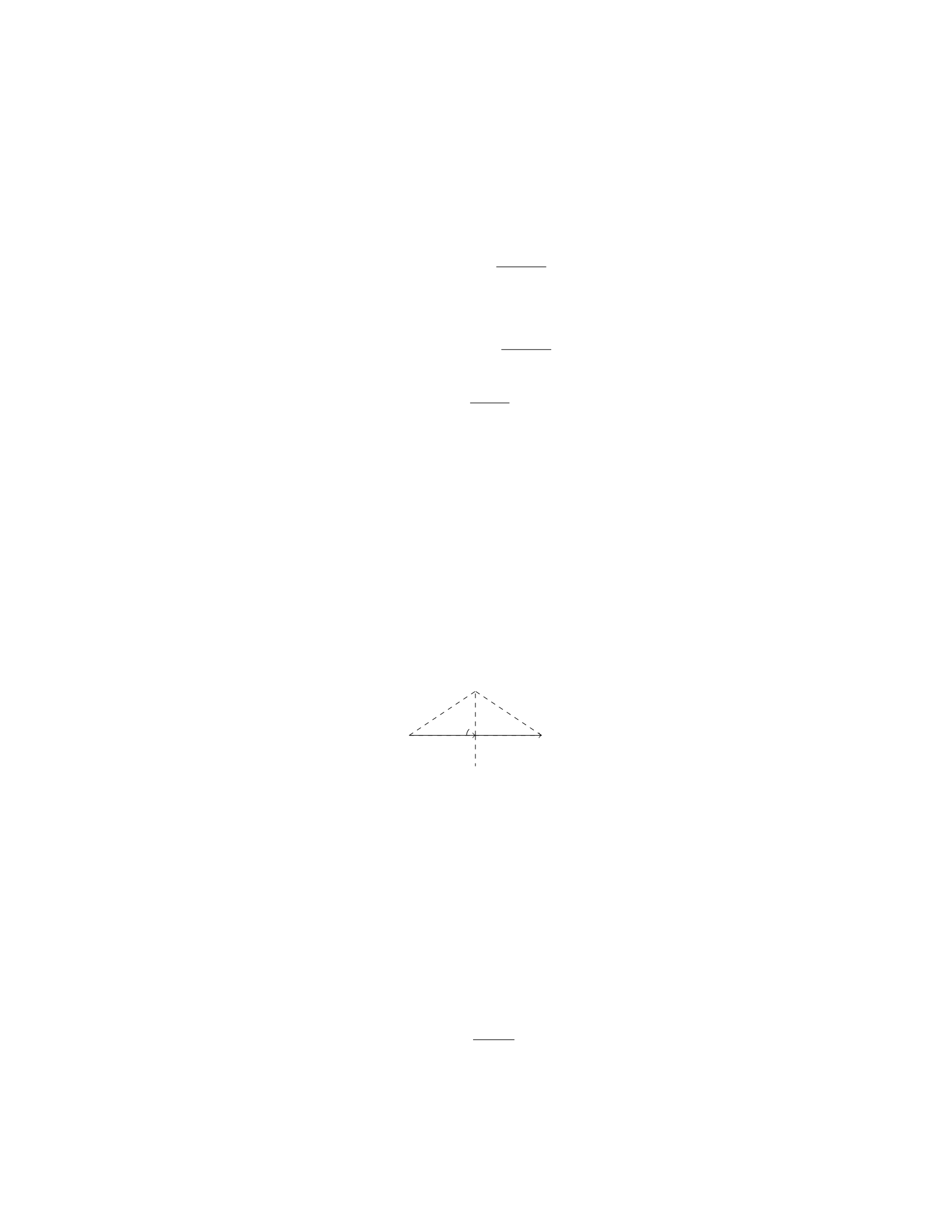
Step 3: The maximum angle from the vertical (θmax) that the rod will make
with the vertical is given by h/L:
θmax = sin−1m2v2
0
2MLg2
Step 4: Finally, we can find the maximum distance dby d=Lsin θmax:
d=Lsin sin−1m2v2
0
2MLg2
d=m2v2
0
2Mg2
Question 12
Question
A uniform beam of length Land mass Mis supported by two cables, one
attached a distance afrom one end and the other attached a distance bfrom
the other end (where a+b=L). The beam is in equilibrium and makes an
angle θwith the horizontal. Find an expression for the tension in each cable in
terms of M,L,a,b, and θ.
Solution
Step 1: Draw a free-body diagram of the beam.
T1T2
Mg
θ
L
θ
Step 2: Write equations for the forces in the x and y directions. In the
x-direction:
T1sin θ−T2sin θ= 0
In the y-direction:
T1cos θ+T2cos θ−Mg = 0
Step 3: Simplify the equations. From the first equation, we have T1=T2.
Substitute this into the second equation to get:
2T1cos θ−Mg = 0
Step 4: Solve for T1.
T1=Mg
2 cos θ
11

Step 5: Substitute in θusing trigonometry.
T1=Mg
2 cos arccos b
L
Step 6: Simplify the expression.
T1=Mg
2b
L=MLg
2b
Step 7: Find the tension in the second cable, T2. Since T1=T2, we have:
T2=MLg
2a
Therefore, the tension in each cable is MLg
2band MLg
2a, respectively.
Question 13
Question
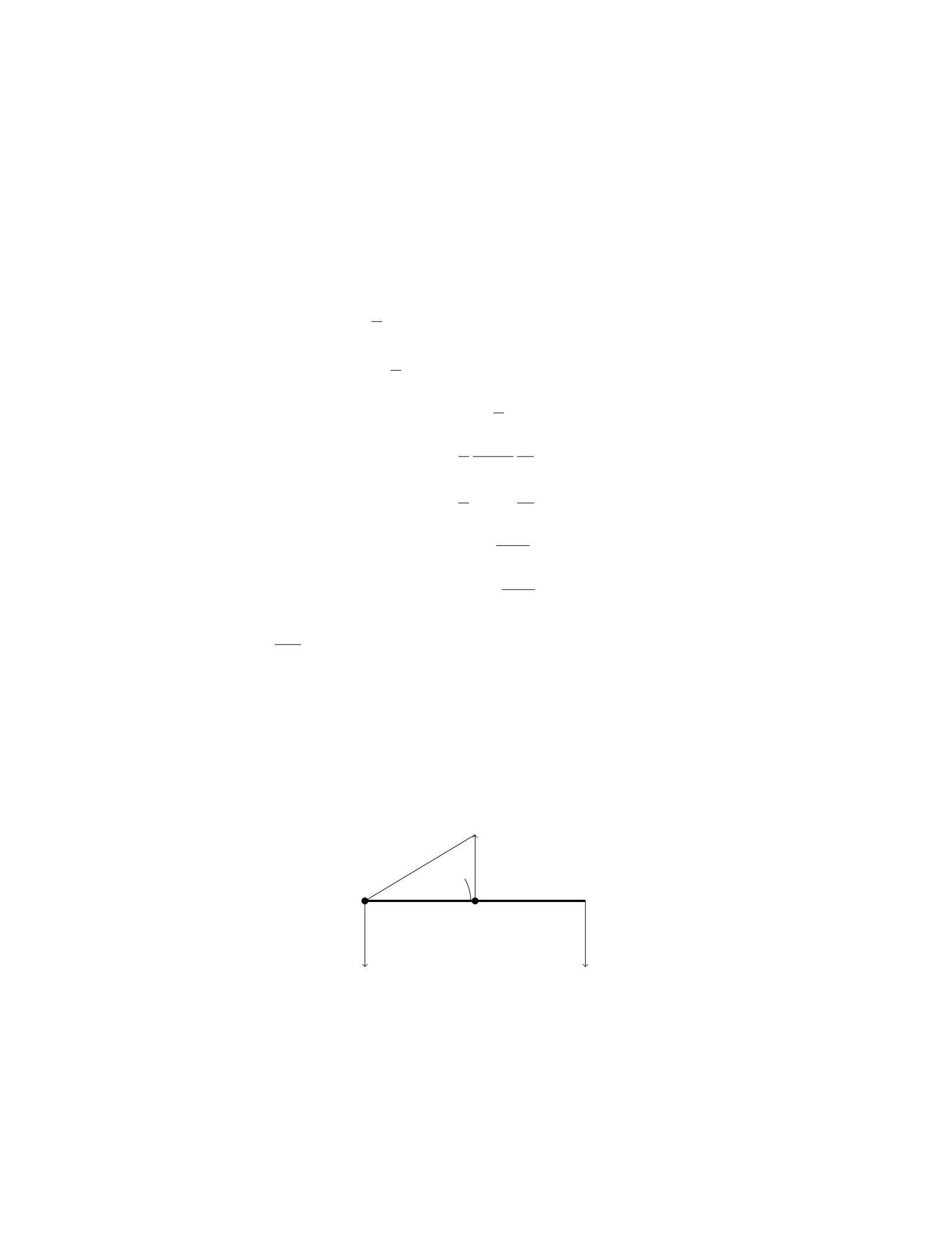
A uniform rod of mass mand length Lis suspended vertically from one end. A
block of mass Mis placed at a distance xfrom the end of the rod, causing the
rod to tilt by an angle θ. Assuming the system is in equilibrium, determine the
expression for θin terms of m,M,L,x, and acceleration due to gravity g.
Solution
To solve this problem, we will first define the forces acting on the system and
then analyze the torques about the point of suspension to find the equilibrium
condition.
Step 1: Define the forces The forces acting on the system are the gravi-
tational forces on the rod, block, and the tension in the rod. Let’s denote: - T
as the tension in the rod, - Fg,rod as the gravitational force on the rod, - Fg,block
as the gravitational force on the block.
Step 2: Analyze the torques Taking moments about the point of sus-
pension (the end of the rod), the torques must sum to zero to be in equilibrium.
The torque from the tension Tdoes not apply any torque about this point since
its line of action passes through the point. The torques from the gravitational
forces are: - Torque from the rod: τrod =−L
2sin(θ)Fg,rod - Torque from the
block: τblock =−xcos(θ)Fg,block
Step 3: Write the equilibrium condition The net torque about the
point of suspension must be zero for equilibrium:
−L
2sin(θ)Fg,rod −xcos(θ)Fg,block = 0
12
Step 4: Express the gravitational forces in terms of masses and
acceleration due to gravity The gravitational forces can be expressed as:
Fg,rod =m·g Fg,block =M·g
Step 5: Solve for θSubstitute the expressions for gravitational forces into
the equilibrium condition and solve for θ:
−L
2sin(θ)m·g−xcos(θ)M·g= 0
−L
2sin(θ)m−xcos(θ)M= 0
xcos(θ)M=−L
2sin(θ)m
x=−L
2
sin(θ)
cos(θ)
m
M
x=−L
2tan(θ)m
M
tan(θ) = −2xM
Lm
θ= arctan −2xM
Lm
Therefore, the expression for θin terms of m,M,L,x, and gis θ=
arctan −2xM
Lm .
Question 14
Question
A uniform beam of length Land mass Mis supported by two ropes attached
at points Aand B, as shown in the diagram below. The beam makes an angle
of θwith the horizontal. Determine the tension in each rope.
BA
TATB
θ
Mg
Assume the beam is weightless and the tension due to the ropes at points A
and Bact along the length of the beam.
13

Solution
Step 1: First, draw the free-body diagram of the beam.
Step 2: Resolve the forces into their x and y components. Let’s choose the
x-axis to be parallel to the beam and the y-axis to be perpendicular to the beam.
Step 3: Consider the forces acting on the beam in the y-direction. The
sum of forces in the y-direction must be zero since the beam is in equilibrium.
Therefore, we have:
TAcos(θ) + TBcos(θ)−Mg = 0
Step 4: Now consider the forces acting on the beam in the x-direction. The
x-components of the tensions TAand TBmust balance each other. Therefore,
we have:
TAsin(θ) = TBsin(θ)
Step 5: Solve the equations obtained in steps 3 and 4 to find the tensions
TAand TB. From the x-direction equation in Step 4, we have:
TB=TA
Step 6: Substitute TB=TAinto the y-direction equation in Step 3 to find
the value of tension TA:
TAcos(θ) + TAcos(θ)−Mg = 0
2TAcos(θ) = Mg
TA=Mg
2 cos(θ)
Step 7: Therefore, the tension in each rope is Mg
2 cos(θ).
Question 15
Question
A uniform rod of length Land mass Mis hanging vertically with one end
attached to a fixed point and the other end free. A bullet with mass mand
velocity vis fired horizontally and gets embedded in the free end of the rod.
Find the maximum angle the rod can swing from the vertical.
Solution
1. Let’s denote the angle the rod makes with the vertical as θ. We can find the
velocity of the bullet-rod system just after the collision by using conservation
of momentum in the horizontal direction:
M·0=(M+m)·vfinal cos θ
14

vfinal cos θ= 0
vfinal = 0
2. We can also write the conservation of energy equation for the system at
the maximum angle θmax:
Mgh =1
2(M+m)(vfinal)2+Iω2
where his the height at the maximum angle, I=1
3ML2is the moment of
inertia of the rod about its end, and ωis the angular velocity at that angle.
3. Since vfinal = 0, the equation simplifies to:
Mgh =1
2Iω2
4. The gravitational force provides the centripetal force at the maximum
angle:
Mg cos θmax =M+m
2ω2Lsin θmax
5. Substituting ω=vfinal
L= 0, we get:
Mg cos θmax = 0
cos θmax = 0
θmax =π
2
Therefore, the maximum angle the rod can swing from the vertical is π
2
radians or 90 degrees.
Question 16
Question
A uniform rod of length Land mass Mis supported by a pivot at one end.
A block of mass mis attached to the other end of the rod. The system is
in rotational equilibrium when the rod makes an angle θwith the vertical.
Calculate the tension in the rod at this angle.
Solution
To find the tension in the rod at angle θ, we can analyze the torques acting on
the system.
Step 1: Draw a free-body diagram and establish the forces acting on the
system.
15

–The forces acting on the system are the tension in the rod (T), the
force of gravity on the rod (M g), and the force of gravity on the block
(mg).
–The torque due to the tension Tand the forces of gravity must sum
to zero for the system to be in rotational equilibrium.
Step 2: Write the torque equilibrium equation. The torque equilibrium
equation is given by:
Xτ= 0
where the torques are calculated about the pivot point. Torques causing
a clockwise rotation are taken as negative, while those causing a counter-
clockwise rotation are taken as positive.
Step 3: Calculate the torques. The torques in the system are:
–Torque due to tension T: It acts at a distance Lfrom the pivot point
in the counterclockwise direction, so its torque is +T·Lsin(θ).
–Torque due to the block’s weight mg: It acts at a distance Lcos(θ)
from the pivot point in the clockwise direction, so its torque is −mg ·
Lcos(θ).
–Torque due to the rod’s weight Mg: It acts at a distance L/2 from
the pivot point in the clockwise direction, so its torque is −Mg ·L/2.
Step 4: Set up the torque equilibrium equation.
Xτ=T·Lsin(θ)−mg ·Lcos(θ)−Mg ·L/2 = 0
Step 5: Solve for the tension T.
T·Lsin(θ) = mg ·Lcos(θ) + Mg ·L/2
T=mg ·Lcos(θ) + Mg ·L/2
Lsin(θ)
T=mg cos(θ) + Mg/2
sin(θ)
Question 17
Question
A uniform beam of length Land mass mis supported by a pivot at one end and
a cable connected to the ceiling at the other end. The beam makes an angle of
θwith the ceiling and is in rotational equilibrium. If the tension in the cable is
T, express the tension in terms of m,g,L, and θ.
16
Solution
Step 1: Draw the free-body diagram of the beam.
There are two forces acting on the beam: the gravitational force mg acting
downward at the center of mass and the tension Tacting upwards at an
angle θwith the vertical.
Resolve the tension force into vertical and horizontal components. The
vertical component is Tcos(θ) and the horizontal component is Tsin(θ).
Step 2: Write the torque equation using the pivot point at one end of the
beam.
The torque due to the tension force about the pivot point is τT= (L/2)(Tcos(θ)).
The torque due to the gravitational force about the pivot point is τmg =
−(L/2)(mg sin(θ)).
Since the beam is in rotational equilibrium, the sum of the torques must
be zero: τT+τmg = 0.
Step 3: Solve for the tension T.
Setting τT+τmg = 0 gives (L/2)(Tcos(θ)) −(L/2)(mg sin(θ)) = 0.
Simplifying the equation gives T=mg tan(θ).
Therefore, the tension in the cable in terms of m,g,L, and θis T=
mg tan(θ).
Question 18
Question
A uniform beam of length Land mass M, supported by a cable, is in equilibrium
at an angle θas shown below. The beam has a mass mhanging from one end.
Find the tension in the cable.
17
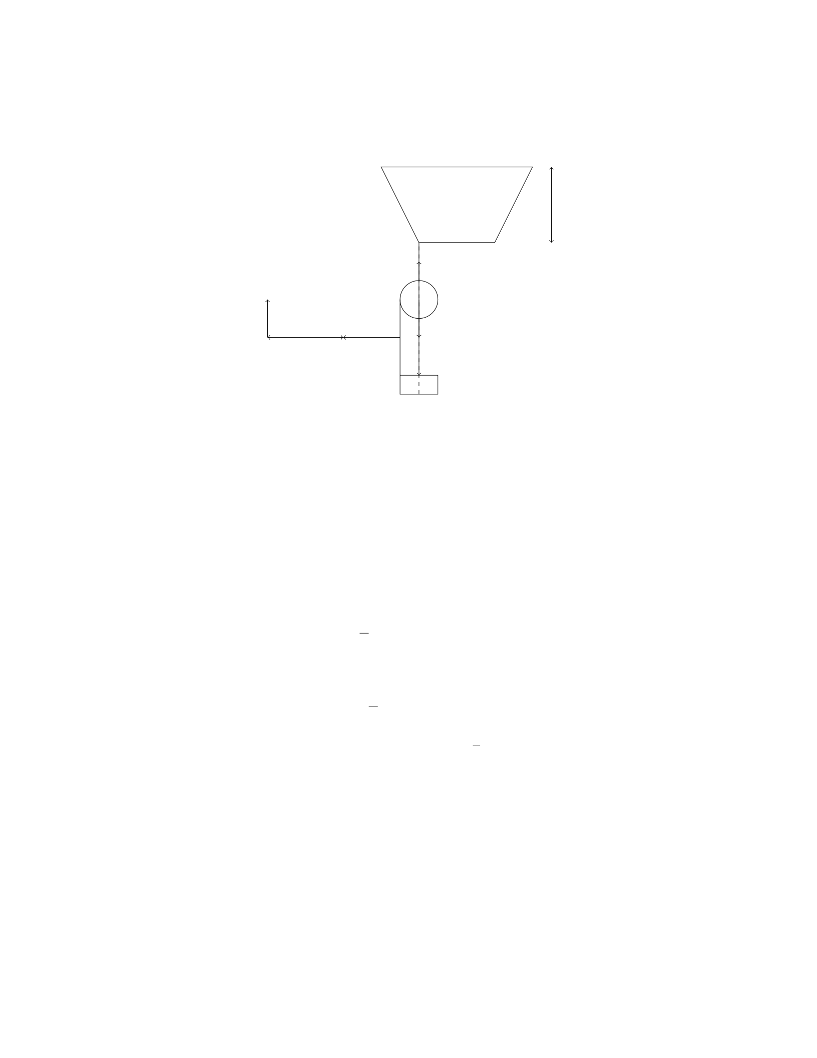
L
m
M
T
x
θ
Solution
To find the tension in the cable, we will first calculate the torque exerted by the
forces around the pivot point O.
Step 1: Set up the torques equation The torques must sum to zero in
order for the beam to be in equilibrium. The torques are calculated about the
pivot point O. Let’s consider the forces that produce a torque:
- The force Tat a distance xfrom the pivot point produces a counterclock-
wise torque: T x. - The force mg at the center of mass (located at L/2 from
O) produces a clockwise torque: mg(L/2) sin(θ). - The force Mg at the far end
(located at Lfrom O) produces a clockwise torque: MgL sin(θ).
Since the beam is in equilibrium, the torques sum to zero:
T x −mg L
2sin(θ)−MgL sin(θ)=0
Step 2: Solve for the tension TSolving for the tension T, we get:
T=mg L
2sin(θ)+MgL sin(θ)
Therefore, the tension in the cable is T=mg L
2sin(θ)+MgL sin(θ).
Question 19
Question
A uniform rod of length Land mass Mis hinged at one end. A force Fis
applied horizontally at the other end (away from the hinge) such that the rod
makes an angle θwith the horizontal. Calculate the magnitude and direction
of the force Fneeded to keep the rod in equilibrium.
18
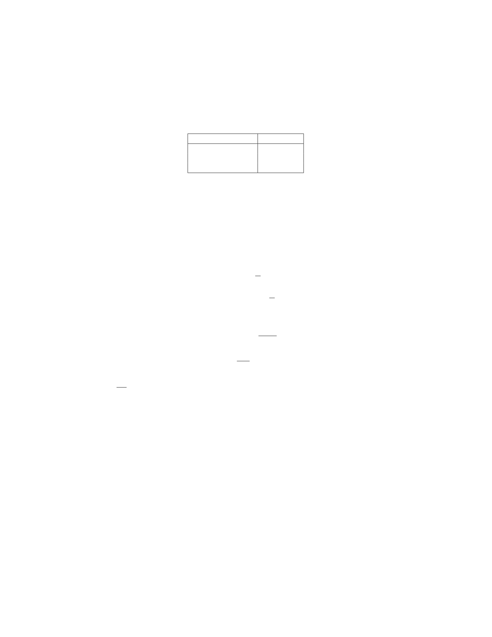
Solution
Step 1: Draw a free-body diagram of the rod.
Force Magnitude
Tension (T)Lcos(θ)F
Weight (Mg)Mg
Normal force (N)N
Step 2: Write the equations of equilibrium in the horizontal and vertical
directions: XFhorizontal = 0 : T=F
XFvertical =0:N=Mg
Step 3: Write the torque equation with respect to the hinge point:
τ= 0
T(Lsin(θ)) −Mg(L
2cos(θ)) = 0
Lcos(θ)F(Lsin(θ)) −Mg(L
2cos(θ)) = 0
Step 4: Solve for Ffrom the torque equation:
F L sin(θ) = MgL
2
F=Mg
2csc(θ)
Therefore, the magnitude of the force Fneeded to keep the rod in equilibrium
is Mg
2csc(θ). The direction of the force is opposite to the direction of the force
applied initially.
Question 20
Question
A uniform beam of length Land mass Mis supported by a vertical cable
attached at its midpoint. A box of mass mis placed at the end of the beam. If
the tension in the cable is equal to half the weight of the beam, determine the
distance of the box from the end of the beam for the system to be in equilibrium.
19

Solution
Step 1: Draw a free body diagram of the system. Let Tbe the tension in the
cable, Wbe the weight of the beam, M g be the downward force due to gravity
acting on the beam, mbe the mass of the box, and mg be the downward force
due to gravity acting on the box. The distance of the box from the end of the
beam is denoted as x. The forces acting on the beam are the tension T, weight
W, and the pivot force. The forces acting on the box are the tension Tand its
weight mg. The pivot force acts at the midpoint of the beam.
Step 2: Write the equations for the equilibrium of the system. For transla-
tional equilibrium of the beam along the horizontal axis: Sum of forces in the
horizontal direction = 0 T=1
2W T =1
2Mg
For rotational equilibrium of the system: Sum of torques about the pivot
point = 0 T·L
2=mg ·(L−x)
Step 3: Solve the equations simultaneously. We already know T=1
2Mg.
Substitute the values into the equation for the torque: 1
2Mg ·L
2=mg ·(L−x)
(1
2Mg)·L
2=mg ·L−mg ·x1
4MgL =mgL −mgx
Step 4: Solve for x.mgx =mgL −1
4MgL x =L−1
4
M
mL
Therefore, the distance of the box from the end of the beam for the system
to be in equilibrium is L−1
4
M
mL.
Question 21
Question
A metal wire with length Land cross-sectional area Ais stretched by a force
F. The Young’s modulus of the material is Y. Determine the maximum length
that the wire can be stretched before reaching its elastic limit, assuming it is
initially at equilibrium.
Solution
Step 1: Let’s consider the equilibrium of forces on the wire. At the elastic limit,
the force Fbalances the force due to the stretching of the wire.
Step 2: The force due to the stretching can be calculated using Hooke’s Law,
F=k·∆L, where kis the spring constant (related to the Young’s modulus)
and ∆Lis the change in length of the wire.
Step 3: The change in length ∆Lcan be expressed as F
A·Y, where Ais the
cross-sectional area of the wire and Yis the Young’s modulus.
Step 4: Setting F=k·F
A·Yand solving for k, we find k=A·Y
L.
Step 5: Now, we can find the maximum length the wire can be stretched
before reaching its elastic limit. At this point, the force Fequals the yield
strength of the material.
Step 6: The yield strength is the stress at which the material undergoes
permanent deformation. It can be calculated as F
A.
20

Step 7: Setting F
A=k·∆L, we find ∆L=F L
AY .
Step 8: Therefore, the maximum length the wire can be stretched before
reaching its elastic limit is F L
AY .
Question 22
Question
A block of mass mhangs from a spring scale attached to the ceiling of an
elevator. When the elevator is accelerating upward at aup, the scale reads N1.
When the elevator is accelerating downward at adown, the scale reads N2. Find
the spring constant of the scale.
Solution
Step 1: Identify the forces acting on the block when the elevator is moving
upward: The forces acting on the block are its weight mg, the tension in the
spring scale N1, and the normal force due to the elevator floor N. Applying
Newton’s second law in the vertical direction, we have:
N1−mg =maup
Step 2: Identify the forces acting on the block when the elevator is moving
downward: The forces acting on the block are its weight mg, the tension in the
spring scale N2, and the normal force due to the elevator floor N. Applying
Newton’s second law in the vertical direction, we have:
N−N2=madown
Step 3: Since the block is in equilibrium when stationary, the normal force N
is equal to the weight mg. Thus, we get:
N=mg
Step 4: Substitute N=mg in the equations from Step 1 and Step 2: For the
upward acceleration:
N1−mg =maup
For the downward acceleration:
mg −N2=madown
Step 5: Since N1and N2are the readings of the spring scale, they can be related
to the spring constant kby N1=kx and N2=−kx, where xis the displacement
of the block. Step 6: Substitute N1=kx and N2=−kx into the equations
from Step 4: For the upward acceleration:
kx −mg =maup
21

For the downward acceleration:
mg +kx =madown
Step 7: Adding the two equations from Step 6, we get:
2kx =m(aup +adown)
Step 8: Rearrange the equation to solve for the spring constant k:
k=m(aup +adown)
2x
Question 23
Question
A 2.5 m long uniform beam of mass 10 kg is supported at each end with a 80 kg
mass placed 0.8 m from the left end. What is the tension in the left support?
(Assume g = 9.81 m/s2)
Solution
Step 1: Draw a free-body diagram of the beam. There are three forces acting
on the beam: the weight of the beam itself, the weight on the left end, and the
weight on the right end. Call the tension in the left support TLand the tension
in the right support TR. Step 2: Write the equilibrium condition for forces in
the vertical direction. The sum of all forces in vertical direction is zero. Step 3:
Express weight of the beam and masses in terms of their masses and acceleration
due to gravity. Step 4: Write the torque equilibrium condition. The sum of all
torques acting on the beam must be zero. Step 5: Express torque due to the
weight of the beam and masses. Step 6: Solve the equations simultaneously to
find TL.
TL=1
2(Mb+M1+M2)g
Plugging in the given values,
TL=1
2(10 + 80 + 80) ×9.81
TL= 245.25 N
Therefore, the tension in the left support is 245.25 N.
22
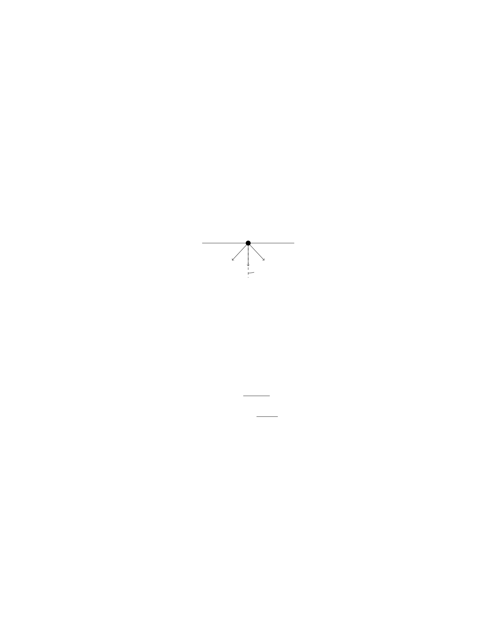
Question 24
Question
A uniform rectangular beam of length Land mass Mis supported by two ropes
attached to the ends of the beam. If the angle between each rope and the beam
is θ, find the tension in each rope in terms of M,g,L, and θ.
Solution
Let’s denote the tension in each rope as T. To start, we need to draw a free
body diagram of the beam. There are three forces acting on the beam: the
gravitational force Mg acting downward, and the two vertical components of
the tensions in the ropes.
Mg
T T
θ
Note that the forces must add up to zero in both the horizontal and vertical
directions since the beam is in equilibrium.
Step 1: Resolve Tinto horizontal and vertical components. The vertical
component of each tension Tis Tcos(θ).
Step 2: Write the equation for the vertical forces. Summing the forces in
the vertical direction:
2Tcos(θ) = Mg
Step 3: Solve for the tension in each rope. Dividing both sides by 2, we
get:
T=Mg
2 cos(θ)
Therefore, the tension in each rope is Mg
2 cos(θ).
Question 25
Question
A 2.00 m long steel wire with a radius of 1.00 mm is stretched to a tension of
100 N. If Young’s modulus for steel is 2.00×10¹¹ N/m2, calculate the maximum
energy the wire can store elastically before it permanently deforms.
23

Solution
Step 1: Calculate the cross-sectional area of the wire. Given the radius of the
wire, r= 1.00 mm = 1.00 ×10⁻³m. The cross-sectional area, A, of the wire is
given by:
A=πr2
A=π×(1.00 ×10⁻³)2
A=π×1.00 ×10⁻⁶
A= 3.14 ×10⁻⁶m2
Step 2: Calculate the elastic modulus of the wire. Given Young’s modulus,
Y= 2.00 ×10¹¹ N/m2.
Step 3: Calculate the strain in the wire. The strain, ε, in the wire is given
by:
ε=F
A·Y
ε=100
3.14 ×10−6×2.00 ×1011
ε=100
6.28 ×10⁵
ε= 1.59 ×10⁻⁴
Step 4: Calculate the elastic potential energy stored in the wire. The elastic
potential energy, U, stored in the wire is given by:
U=1
2F·ε·L
U=1
2×100 ×1.59 ×10−4×2.00
U= 0.0796 J
Therefore, the maximum energy the wire can store elastically before it per-
manently deforms is 0.0796 J.
Question 26
Question
A horizontal plank of mass mand length Lis supported by two ropes attached
to the ends of the plank. The angles that the ropes make with the horizontal
are θ1and θ2, as shown in the figure. If the tension in the rope attached to the
left end of the plank is T1and the tension in the rope attached to the right end
is T2, determine the horizontal and vertical forces on the plank.
equilibrium_diagram.png
24
Solution
Step 1: Draw a free body diagram of the plank.
Forces Directions
T1Up and to the left at angle θ1
T2Up and to the right at angle θ2
mg Downward
NUpward
Step 2: Break down the forces into their components.
The forces T1and T2can be broken down into their x- and y-components.
Resolving T1into components, we get:
T1x=T1cos θ1and T1y=T1sin θ1
Similarly, resolving T2into components, we get:
T2x=T2cos θ2and T2y=T2sin θ2
Step 3: Write down the force equations in the x and y directions.
In the x-direction, the forces are balanced:
T1x=T2x
In the y-direction, the forces are balanced as well:
N−mg =T1y+T2y
Step 4: Solve for the horizontal and vertical forces on the plank.
From the x-direction equation, we have:
T1cos θ1=T2cos θ2
From the y-direction equation, we have:
N−mg =T1sin θ1+T2sin θ2
Therefore, the horizontal force on the plank is T1cos θ1=T2cos θ2and the
vertical force on the plank is N=mg +T1sin θ1+T2sin θ2.
Question 27
Question
A uniform bridge has a length of Land a mass M. A car of mass mis parked
at a distance xfrom one end of the bridge. The car exerts a downward force
on the bridge due to its weight. What is the force on the bridge at a distance y
from the end where the car is parked?
25

Solution
Step 1: Let’s first calculate the downward force exerted by the car on the bridge.
This force is equal to the weight of the car, so it can be calculated as Fcar =mg.
Step 2: To find the force at a distance yfrom the end where the car is
parked, we need to analyze the forces acting on a small section of the bridge of
length ∆yat that point.
Step 3: The forces acting on this section are the gravitational force (due to
the bridge’s own weight) and the force from the car. The gravitational force on
this section is ∆Fbridge =−Mg
L∆y, where the negative sign indicates that it is
directed upwards.
Step 4: The net force acting on this section is given by PF= ∆Fbridge +
∆Fcar.
Step 5: Applying Newton’s second law for the vertical direction (PF=ma),
we have ∆Fbridge + ∆Fcar =M∆2y
∆t2.
Step 6: Substituting the expressions for ∆Fbridge and ∆Fcar, we get −M g
L∆y+
mg =M∆2y
∆t2.
Step 7: Simplifying, we have −gM
L∆y+mg =M∆2y
∆t2.
Step 8: In the limit as ∆y→0, this becomes a differential equation: −Mg
Ly+
mg =Md2y
dt2.
Step 9: Solving this differential equation with initial conditions, we can find
the force on the bridge at a distance yfrom the end where the car is parked.
Question 28
Question
A steel cable with a diameter of 2.0 cm supports a load of 5000 N. If the cable
stretches 20 cm under this load, what is the Young’s modulus of the steel?
Solution
Step 1: Find the cross-sectional area of the steel cable. The cross-sectional area
of the cable can be calculated using the formula for the area of a circle:
A=πr2
Given that the diameter of the cable is 2.0 cm, the radius ris 1.0 cm or 0.01 m.
Therefore, the cross-sectional area is:
A=π(0.01 m)2= 3.14 ×10⁻⁴m2
Step 2: Calculate the stress on the cable. Stress is defined as the force
applied per unit area. In this case, the stress applied to the cable is given by:
Stress = Force
Area
26

Substitute the given values to find the stress:
Stress = 5000 N
3.14 ×10⁻⁴m2= 1.59 ×10⁷N/m2
Step 3: Use Hooke’s Law to calculate the Young’s modulus. Hooke’s Law
states that the stress is directly proportional to the strain. In this case, the
strain is the elongation of the cable divided by its original length.
Strain = Change in length
Original length =0.20 m
0.20 m = 1
Now, use Hooke’s Law to find the Young’s modulus:
Stress = Young’s modulus ×Strain
1.59 ×10⁷N/m2= Young’s modulus ×1
Therefore, the Young’s modulus of the steel is 1.59 ×10⁷N/m2.
Question 29
Question
A uniform beam of mass mand length Lis supported horizontally by two
vertical strings, as shown in the diagram below. The tension in the first string
is twice the tension in the second string. The beam is in static equilibrium.
Find the tensions T1and T2in the strings.
m
T1
T2
Solution
Step 1: Identify the forces acting on the beam.
The forces acting on the beam are: - The weight of the beam acting down-
wards at its center, mg. - The tension T1in the first string acting upwards at
the center of the beam. - The tension T2in the second string acting upwards
at the center of the beam.
27

Since the beam is in static equilibrium, the net force and net torque acting
on the beam must be zero.
Step 2: Write the equations for equilibrium.
Net Force in the vertical direction: T1+T2−mg = 0
Net Torque about the center of the beam: T2L
2−T1L
2= 0
Step 3: Solve the equations for T1and T2.
From the first equation, we have T1+T2=mg.
Given that T1= 2T2, we can substitute this into the equation above:
2T2+T2=mg
3T2=mg
T2=mg
3
Substitute T2back into T1= 2T2:
T1= 2 mg
3=2mg
3
Therefore, the tensions in the strings are T1=2mg
3and T2=mg
3.
Question 30
Question
A uniform beam of length Land mass Mis supported at an angle θby a light
string attached at the midpoint of the beam. A weight Wis hung at one end of
the beam. If the tension in the string is T, calculate the tension in the string.
beam.png
Solution
Step 1: Draw the free body diagram of the beam.
The forces acting on the beam are the weight Wacting downward, the
tension Tacting upward at an angle θwith respect to the vertical, and the
gravitational force acting downward at the center of mass. The gravitational
force can be split into a component perpendicular to the beam (M g ·L
2) and
a component parallel to the beam (Mg). Let’s denote the length of the beam
from the pivot point to the end with the weight x.
Step 2: Write the torque equation about the left end of the beam.
Summing up the torques about the left end of the beam, we have:
W·L
2·sin(θ)−T·L
2·cos(θ)=0
28

Step 3: Write the force balance equations in the xand ydirections.
In the vertical direction, we have:
T·sin(θ) = M·g
In the horizontal direction, we have:
T·cos(θ) = W
Step 4: Solve the system of equations.
From the force balance equations, we have:
T=M·g
sin(θ)
And from the torque equation, we have:
W=M·g
tan(θ)
Therefore, the tension in the string is M·g
sin(θ).
Question 31
Question
A uniform iron rod of length 1.5 m and mass 4.0 kg is suspended horizontally
by two vertical steel wires of equal length. The rod is heated to 150
°
C, causing
it to expand. If the coefficient of linear expansion for steel is 1.20 ×10⁻⁵
°
C−1
and the coefficient of linear expansion for iron is 6.50×10⁻⁶
°
C−1, by how much
does the tension in each wire change due to the heating of the rod?
Solution
Step 1: We will first find the change in length of the iron rod when heated.
Given that the coefficient of linear expansion for iron is αiron = 6.50 ×
10−6
°
C−1, the initial length of the iron rod is Liron = 1.5 m, and the change in
temperature is ∆T= 150C.
The change in length ∆Lof the rod can be calculated using the formula:
∆Liron =αiron ·Liron ·∆T
Substitute the given values to find ∆Liron:
∆Liron = (6.50 ×10⁻⁶
°
C−1)·(1.5 m) ·(150C)
∆Liron = 0.0014625 m = 1.463 mm
29

Step 2: Next, we need to determine the change in tension in the steel wires
due to the expansion of the iron rod.
Since the steel wires are of equal length and the iron rod is suspended by
them, the change in length of each steel wire will be half of the change in length
of the iron rod.
Therefore, the change in length of each steel wire can be calculated as:
∆Lsteel =1
2·∆Liron =1
2·0.0014625 m = 0.00073125 m
Step 3: Now we will calculate the change in tension in each steel wire.
Let Tbe the initial tension in each steel wire before heating.
The change in tension ∆Tin each steel wire can be calculated using Hooke’s
Law:
∆T=k·∆Lsteel
where kis the spring constant for each steel wire.
Since the steel wires are under tension, the change in tension will be negative.
Therefore, the change in tension ∆Twill point upward due to the expansion of
the iron rod.
Thus, the magnitude of the change in tension ∆Tin each steel wire will be:
|∆T|=k·∆Lsteel
Step 4: Since both steel wires are identical and experience the same change
in tension, the total change in tension due to the heating of the rod will be
2|∆T|.
Thus, the total change in tension in the steel wires will be:
2|∆T|= 2k∆Lsteel
Question 32
Question
A uniform bridge, of total length L, rests on two supports that are each a
distance dfrom the ends of the bridge. A car of mass mis parked in the middle
of the bridge. If the bridge has a mass M, determine the reaction forces on each
support when it is in equilibrium.
Solution
Let’s denote R1as the reaction force at the left support and R2as the reaction
force at the right support.
Step 1: Identify the forces acting on the bridge. The forces acting on the
bridge include the weight of the bridge itself (Mg), the weight of the car (mg),
the force R1at the left support, and the force R2at the right support.
30

Step 2: Write down the equilibrium equations. In the vertical direction,
the sum of the forces must be zero:
R1+R2−Mg −mg = 0
In the torques equation, we can take the torques about the left support:
R2·(L−d)−Mg ·L
2−mg ·L
2= 0
Step 3: Solve the equilibrium equations. From the vertical equilibrium
equation:
R1+R2=Mg +mg
Substitute R1=Mg +mg −R2into the torque equation:
R2·(L−d)−Mg ·L
2−mg ·L
2= 0
Simplify and solve for R2:
R2·(L−d) = (M+m)Lg
2
R2=(M+m)g·L
2(L−d)
Step 4: Find R1. Substitute the value of R2back into the equation R1+
R2=Mg +mg:
R1=Mg +mg −R2
Now you can calculate the numerical values for R1and R2given the masses
M,m, the length of the bridge L, and the distance of the supports d.
Question 33
Question
A 5 kg block is resting on an inclined plane that makes an angle of 30◦with
the horizontal. The coefficient of static friction between the block and the plane
is 0.4. What is the maximum angle at which the block can sit without sliding
down the incline?
Solution
Step 1: Draw a free-body diagram of the block on the inclined plane. Step 2:
Break the gravitational force into components parallel and perpendicular to the
incline. Step 3: Write the force balance equations for the block in the direction
perpendicular to the incline. Step 4: Write down the force balance equations for
the block in the direction parallel to the incline. Step 5: Set up the inequality
for static equilibrium in the direction parallel to the incline to find the maximum
angle. Step 6: Solve for the maximum angle at which the block can sit without
sliding down the incline.
31
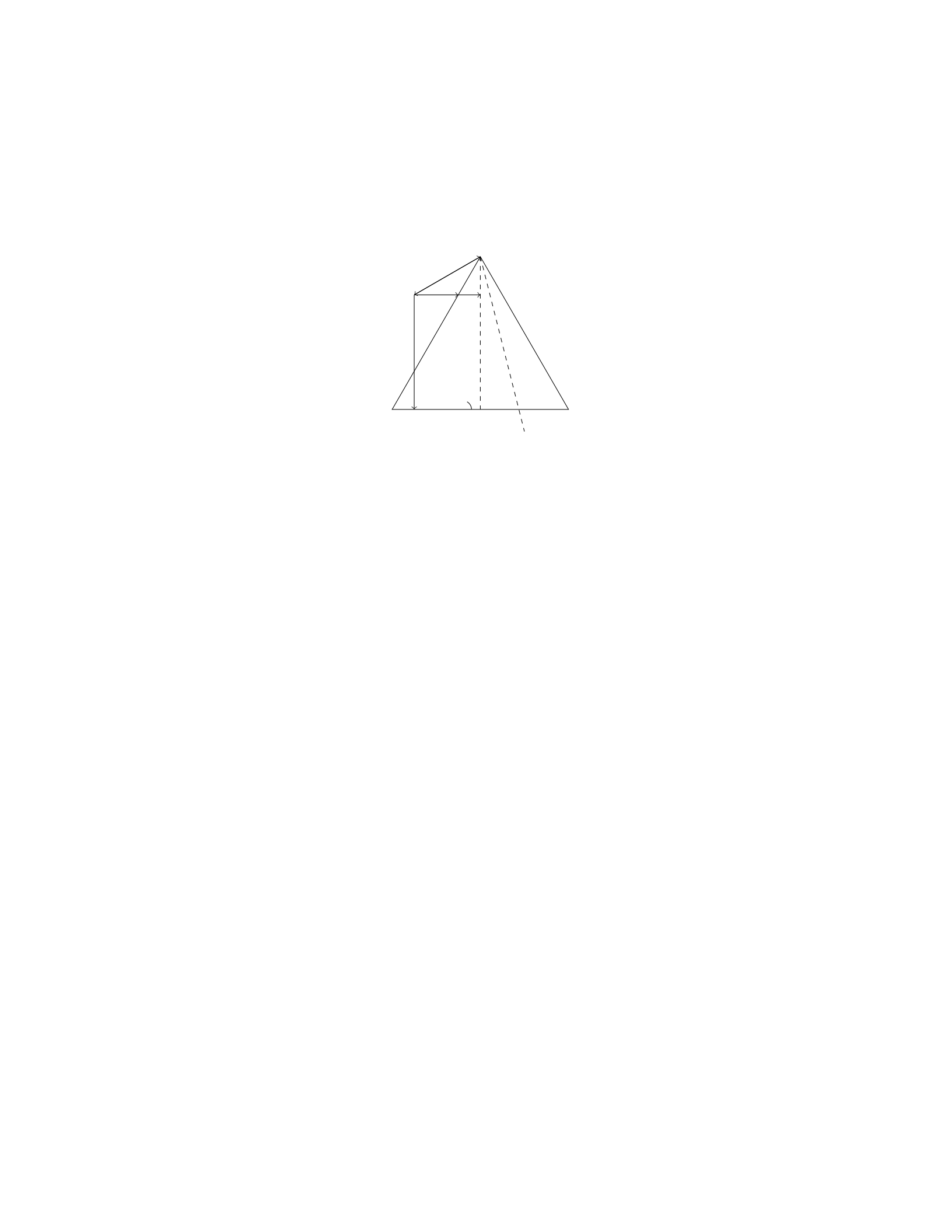
Solution
Step 1: Draw a free-body diagram of the block on the inclined plane.
N
mg
ffriction
fnormal
θ
Step 2: The gravitational force mg can be resolved into components parallel
and perpendicular to the incline:
mg sin(θ)
mg cos(θ)
Step 3: Write the force balance equations for the block in the direction
perpendicular to the incline.
N−mg cos(θ)=0
N=mg cos(θ)
Step 4: Write down the force balance equations for the block in the direction
parallel to the incline.
ffriction −mg sin(θ) = 0
ffriction =mg sin(θ)
Step 5: Set up the inequality for static equilibrium in the direction parallel
to the incline to find the maximum angle:
ffriction ≤µs·fnormal
mg sin(θ)≤µs·mg cos(θ)
sin(θ)≤µs·cos(θ)
Step 6: Solve for the maximum angle at which the block can sit without
sliding down the incline:
tan(θ)≤µs
θ≤arctan(µs)
θ≤arctan(0.4) ≈21.8◦
Therefore, the maximum angle at which the block can sit without sliding
down the incline is approximately 21.8◦.
32
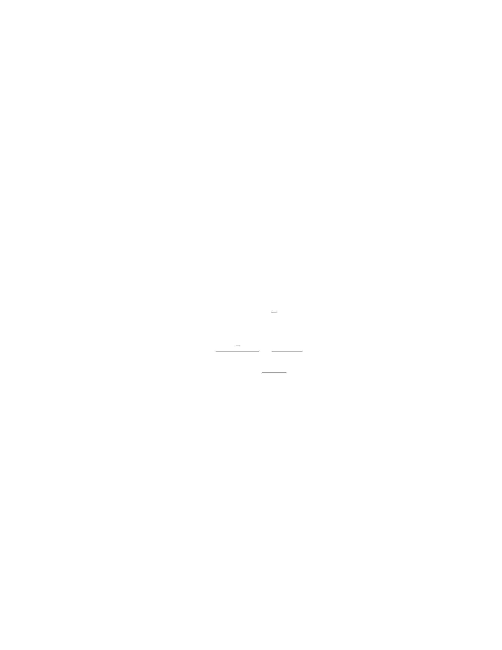
Question 34
Question
A uniform, horizontal beam of length Land mass Mis supported by a cable
attached to its end. The beam makes an angle θwith the horizontal and the
tension in the cable is T. Determine the tension in the cable in terms of L,M,
θ, and g.
Solution
Step 1: We will begin by drawing a free-body diagram of the beam. The
forces acting on the beam are the tension Tin the cable, the gravitational force
Mg acting at the center of mass, and the normal force Nacting at the pivot
point. Step 2: Resolve the gravitational force into components. The vertical
component balances the normal force, and the horizontal component provides
the net torque about the pivot point: Mg cos θ. Step 3: The torque produced
by the tension in the cable is T·Lsin θ(clockwise). There is no torque due to
the normal force as it acts at the pivot point. Step 4: The beam is in rotational
equilibrium, so the net torque about the pivot point is zero. Set up the torque
equation:
T·Lsin θ=Mg ·L
2cos θ
Step 5: Solve the equation for Tto find the tension in the cable:
T=Mg ·L
2cos θ
Lsin θ=Mg cos θ
2 sin θ
Therefore, the tension in the cable is T=Mg cos θ
2 sin θ.
Question 35
Question
A uniform wooden beam of length Land weight Wis supported by a rope at
each end. The beam hangs vertically and is pulled down until it is horizontal.
Determine the tension in each rope when the beam makes an angle θwith the
vertical. Assume the beam has mass M, and its center of mass is located at its
center.
Solution
Step 1: Draw a free-body diagram for the beam in equilibrium. Let’s consider
the forces acting on the beam when it is at an angle θwith the vertical. The
forces acting on the beam are the weight Wacting at the center of mass down-
ward, the tension forces T1and T2acting at each end of the beam, and the
normal force acting perpendicular to the beam at its center.
33

Step 2: Resolve the forces into components. The weight Wcan be re-
solved into two components: Wx=−Wsin(θ) parallel to the beam and Wy=
−Wcos(θ) perpendicular to the beam. The tension forces T1and T2each have
components T1x=T1sin(θ) and T1y=T1cos(θ), and T2x=T2sin(θ) and
T2y=T2cos(θ), respectively.
Step 3: Set up equations for equilibrium in the vertical and horizontal di-
rections. In the vertical direction, the sum of forces equals zero:
T1y+T2y−Wy= 0
T1cos(θ) + T2cos(θ)−Wcos(θ) = 0
Similarly, in the horizontal direction:
T1x+T2x= 0
T1sin(θ) + T2sin(θ)=0
Step 4: Find the tensions in each rope. Since the beam is in equilibrium,
the sum of the torques about any point must be zero. Taking torques about the
center of the beam and using the torque equation:
τ= Force ×Lever Arm
T1·L
2sin(θ)−T2·L
2sin(θ) = 0
T1−T2= 0
T1=T2
Step 5: Substitute T1=T2into the vertical equilibrium equation.
T1cos(θ) + T1cos(θ)−Wcos(θ)=0
2T1cos(θ) = Wcos(θ)
T1=W
2
Therefore, the tension in each rope when the beam makes an angle θwith
the vertical is W
2.
34

