



Introduction Cloud computing has emerged as a de facto
Cloud computing has emerged as a de facto approach throughout society, commercial and
government sectors, and research/academic communities. In fact, the wide usage of mobile
devices means that average users understand the storage and synching of photos, videos, email,
contacts, files, etc., in the cloud. In the last decade, many organizations have considered
outsourcing their IT service to the cloud where the services would have better availability and
quality. However, this requires mobile and desktop clients for different stakeholders, in a domain
such as healthcare, to obtain information from multiple systems, that may be: operating with
different paradigms (e.g., cloud services, programming services, web services); utilize alternate
cloud service providers; and, employ diverse security/access control techniques. This raises two
main problems: services integration and security policies integration. The services integration
problem focuses on the difficulties that occur when a client is trying to access services that could
be operating with different types of application programmer interfaces (APIs). In this case, the
developer of the client will need to work with different paradigms such as programming language
APIs or web services that may be constantly changing and must also be integrated in order to be
successfully utilized for the client. The security policies integration problem occurs since the
different paradigms and alternate cloud service providers may all have different types of security
and access control capabilities, making it very difficult for the developer of the client to realize a
cohesive security solution.
Currently, there is no set of technologies and/or a framework that provides solutions for the
service integration and security policy integration problems. The notion of having a unified set of
global cloud services is one possible solution to the services integration problem. An approach
that supports the combination of different security policies such as Role-Based Access Control

(RBAC) (Ferraiolo, Sandhu, Gavrila, Kuhn, & Chandramouli, 2001), Mandatory Access Control
(MAC) (Bell & La Padula, 1976), or Discretionary Access Control (DAC) (Dittrich, Härtig, &
Pfefferle, 1988), from multiple sources into one global security policy is a possible solution to
the security policies integration. For services integration at the system level, the HL7 Fast
Healthcare
Interoperability Resources (FHIR) (Health Level 7, Fast Health Interoperable Resources list,
2016) provides a service integration infrastructure that can be extended to support RBAC, MAC,
and/or DAC models in which the infrastructure can serve as an initial solution for the two
problems above (i.e., services integration and security policies integration).
The main objective of this dissertation is to provide a solution to the service integration and
security policy integration problems that will allow clients and systems to interact with one
another in a framework. Such a framework would provide the unification of services and
security capabilities from different paradigms (e.g., cloud services, programming services, web
services), alternate cloud service providers, and diverse security/access control (RBAC, MAC,
and/or DAC); the main intent of the unification is to offer global services that can be available to
clients and systems alike. Towards this main objective, this dissertation presents a Framework for
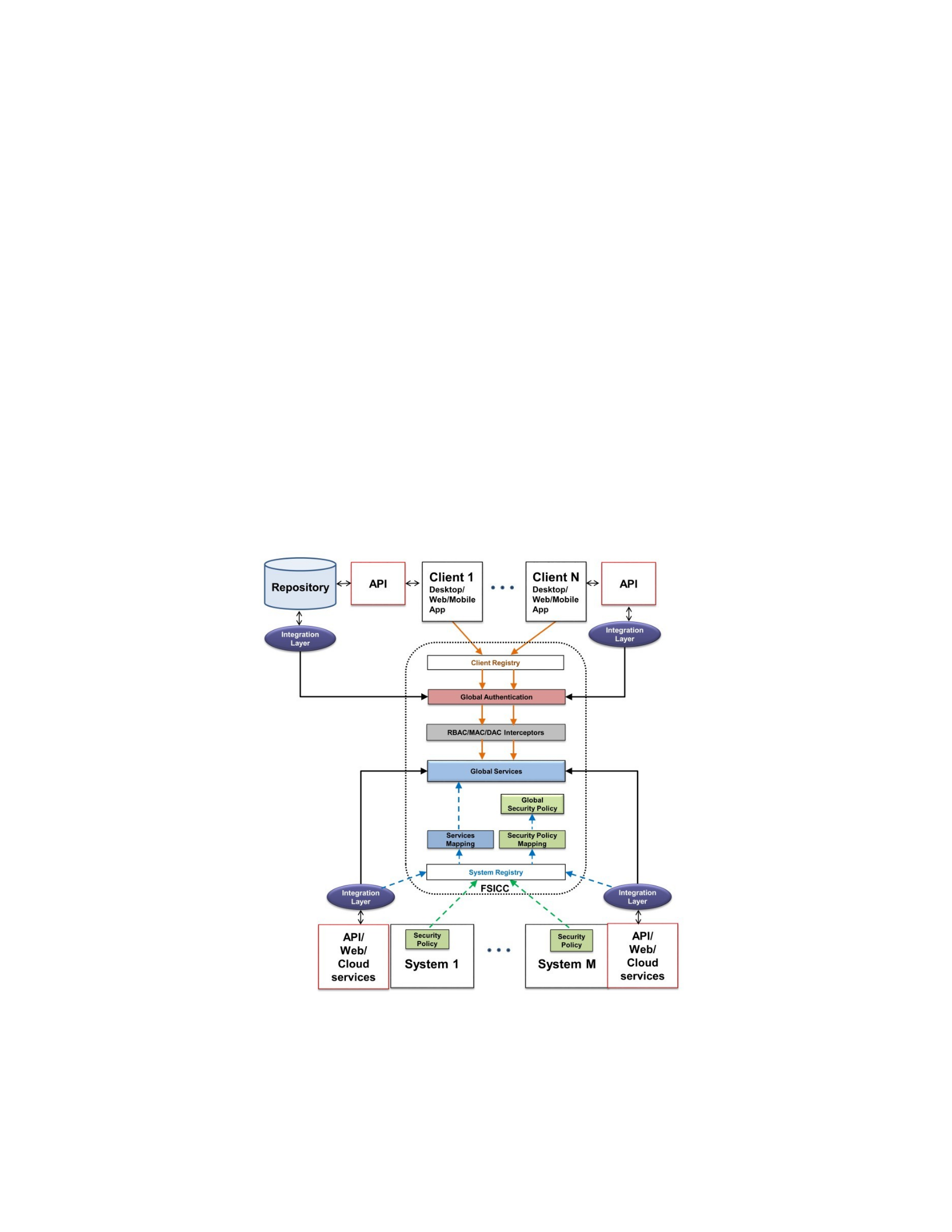
Secure and Interoperable Cloud Computing (FSICC), shown in Figure 1.1, that provides a set of
global cloud services for use by clients and systems with access control provided by RBAC,
MAC, and/or DAC.
To facilitate the discussion of Figure 1.1, we briefly review the following key terms:
application programmer interface (API), web service, cloud service, system, client, and registry.
An API is a general concept that creates a programming interface for a system that can be utilized
by another system or application without disclosing the actual source code of that system. In this
dissertation, API refers to the programming interface for legacy programming languages such as
Java, C++, C, etc. A web service is a programming interface (such as REST and SOAP) that
typically operates over the Hypertext Transfer Protocol (HTTP). A cloud service is a web service
hosted in a cloud environment that makes a cloud service more available and accessible than a
normal web service. A system is a type of software that provides services that can be API, web
services, or cloud services, where the system is intending to publish its services to FSICC. A
client is a desktop, web, or mobile application that is built using different sets of services (API,
web services, or cloud services) provided by systems via FSICC. A registry is a special service of
FSICC that enables a system to register and add its services to FSICC (System Registry), and, a
client to utilize services of FSICC (System Registry).
Figure 1.1. The Framework for Secure and Interoperable Cloud Computing (FSICC).
FSICC as presented in Figure 1.1 has two main actors that are interacting via FSICC to
develop applications in the service-oriented architecture (SOA) manner (IBM, 2015). These

actors are Clients, top of Figure 1.1, and Systems, bottom of Figure 1.1. From an overall
viewpoint, each system builds and publishes their cloud, programmatic, or web services, as
shown at the bottom of Figure 1.1. Then, a developer of a mobile or desktop client, at the top of
Figure 1.1, discovers such services and utilizes them to develop the client application. The
FSICC in the middle of Figure 1.1, augments SOA application development with two additional
layers and their interactions: Global Services and Global Security Policy boxes. The interactions
of clients and systems with FSICC occurs in a number of different ways. From a system
perspective, each system creates an Integration Layer API in front of their API and modifies their
Security Policy to be defined against the Integration Layer API. Each system then registers the
system’s name, the Integration Layer API, and the Security Policy into the FSICC using the
Systems Registry box in the middle of Figure 1.1.
In support of systems, the security engineer of the FSICC creates a global resource that
includes: a set of Global API (Services) based the integration layer APIs of each system utilizing
the Services Mapping box; and, a Global Security Policy based on systems’ Security Policies
which utilizes the Security Policy Mapping box in the middle of Figure 1.1. From a client
perspective, each client creates an Integration Layer API, top of Figure 1.1, in front of their API.
Each client then registers the client’s name into the FSICC, using the Clients Registry box and
reconfigures the client Integration Layer API to call the Global API. In support of clients, the
security engineer of the FSICC performs actions that: associates each registered client with one
of
the registered systems; and, defines a Global Security Policy that enables the
authorized/authenticated clients, via the RBAC/MAC/DAC Interceptor and Global
Authentication boxes in the middle of Figure 1.1, to access services of the appropriate system

based on the client and system names. Note that in Figure 1.1, registered clients are first
authenticated by the Global Authentication box and then authorized by the RBAC/MAC/DAC
Interceptor box, before access to Global Services is allowed.
1.1 Motivation for Access Control for Cloud Computing
Cloud computing provides services in the cloud to be utilized by mobile applications/users
and businesses. The Gartner group indicated that cloud computing represents the majority of IT
funding by 2016 (Shetty, 2013). The International Data Corporation (Idc.com, 2015) reported
that organizations and enterprises around the world spent approximately $70 billion to adopt
cloud computing services in 2015 with the number of cloud-based services expected to triple by
2020.
Cloud computing is provided by major corporations such as Amazon (Amazon.com, 2016),
AT&T (AT&T, 2016), Dell (Dell.com, 2016), etc. Security breaches have come to the forefront
(Kelion, 2014) especially in personal cloud storage (Wingfield, 2015). Outsourced data and
services are located on servers that belong to security domains which are different from an
organization’s security domain, raising numerous security and privacy issues (Takabi, Joshi, &
Ahn, 2010). Other efforts have included: a survey of the different data/network security,
authentication, authorization, and confidentiality issues that impact cloud computing (Subashini
& Kavitha, 2011); a review of the available cloud computing advances in concepts,
functionalities, unique features, and technologies (Wang, Von Laszewski, Younge, He, & Kunze,
2010); and, the characterization of cloud computing as the likely dominant technology for
computing on the

Internet (Pallis, 2010).
Outsourcing services to the cloud has many advantages including (Skyhigh Networks., 2016):
better availability, since most cloud providers ensure more that 90% uptime; better mobility
where the hosted services are typically accessible from any place on earth as long as internet
connection is available; and cost effective due to that fact that computing equipment are provided
by the cloud provider. Such advantages attract governments and businesses to move their services
to the cloud. However, the movement to the cloud has resulted in new attacks to illegally access a
crucial and sensitive data, such as electronic health records of large number of patients. This is
possible since these cloud services are typically designed to be utilized without any type of
access control. There is an emergent need to control who can access which cloud services at
which times and under which conditions. The publishing of services in the cloud leads to a large
number of consumers of such services in which controlling access to which services each
consumer can utilize is not supported in existing paradigms (e.g., cloud services, programming
services, web services), and available cloud service providers. One approach is to have cloud
services controlled using the three main aforementioned access control models, RBAC, MAC,
and DAC, since they provide unique capabilities that can control how services are accessed by
users, clients, and systems.
RBAC provides an efficient way to manage consumers by using the concept of role in which
each role can be authorized to access a sub-set of the available cloud services and each consumer
is assigned one or more suitable roles. When cloud services need to access very sensitive
information such as patient data that needs to be more strongly controlled than other parts of the
patient data, MAC can be employed to control access to services. In this case, MAC can be
utilized to label cloud services and their consumers using sensitivity levels which are

hierarchically ordered from most to least secure: Top Secret (TS) < Secret (S) < Confidential (C)
< Unclassified (U). Using MAC, each cloud service can be assigned a sensitivity level known as
a classification, and each consumer can be assigned a sensitivity level known as a clearance
along with read and write properties. DAC can offer the ability of a consumer of the cloud
services to enable another consumer to utilize all or a sub-set of its authorized cloud services
(that are assigned based on a role or a clearance) through a delegation of authority. In this case,
DAC can be utilized to keep a list of delegated services, along with authorized delegated users,
where each consumer can delegate all or a subset of his/her authorized cloud services to another
consumer anytime.
1.2 Motivation for Healthcare Systems and Applications
In this dissertation, we utilize healthcare as the primary vehicle to justify and explain our work
since it represents as a critical emergent application for cloud computing. In the United
States, the Center of Medicare and Medicaid Services released the Meaningful Use Stage 3
(Himss.org., 2016) guidelines that require all health information technology (HIT) systems to
have cloud services to access, modify, and exchange health-related data. HIT systems include
electronic health records (EHR) such as OpenEMR (OpenEMR, 2016), OpemMRS (OpenMRS
Inc., 2016), and Drchrono EHR (Gibraltar Dr., 2016); and personal health records (PHR) such as
Google Health (Google Inc., 2016), Microsoft HealthVault (Microsoft Inc., 2016), and WebMD
(WebMD LLC., 2016). In support of the interoperability and exchange of healthcare data, the
international Health Level 7 (HL7) (Health Level 7, Health Level Seven INTERNATIONAL,
2016) organization has taken a leadership role for standards to allow the integration, sharing, and

exchange of electronic healthcare data, specifically: HL7 Version 2 (Health Level 7, HL7 Version
2, 2016), HL7 Version 3 (Health Level 7, HL7 Version 3, 2016), the Clinical Document
Architecture (CDA) (Health Level 7, Clinical Document Architecture, 2016), and HL7 Fast
Healthcare Interoperability Resources (HL7 FHIR) (Health Level 7, Fast Health Interoperable
Resources, 2016).
In support of this dissertation, we strongly leverage the Healthcare Interoperability Resources
(FHIR) which provides a RESTful Application Program Interface (API) to share data in a
common format. FHIR conceptualizes and abstracts information for HL7 into 119 currently
defined (and always increasing) Resources that effectively decompose HL7 into logical
components to track a patient’s clinical findings, problems, allergies, adverse events, history,
suggested physician orders, care planning, etc. The intent is to allow a unified access to FHIR’s
RESTful health-related data sharing APIs so that applications can be easily built to uniformly
utilize multiple HIT systems. Concurrent with these activities has been an explosion of mobile
health (mHealth) applications for both patients and medical providers (Aitken, 2013). These
mHealth applications also require access to health data via cloud services from multiple HIT
systems to ensure that all of the necessary information is collected for patient care. Each of these
HIT systems may operate with different paradigms (e.g., cloud, API, web services) and employ
different security/access control techniques. Thus, mHealth applications would need to work
with a heterogeneous collection of paradigms and security protocols, with the strongly likelihood
that set of information sources may grow or shrink over time. This makes it problematic to
develop mHealth applications that are easily maintained and evolved.
The main issue for healthcare is to ensure that the available services of these HIT systems are
carefully authorized to control which mHealth application can utilize which service at which

time; this is specifically what FHIR has been defined to provide. For example, an HIT system
for a pharmacy would have cloud services for: a physician to submit a prescription (Rx)
electronically to the pharmacy (service S1); a pharmacist to be able to fill the Rx and reduce the
number of refills (service S2); the pharmacist to send notification via text/phone to the patient that
the Rx is available (service S3); the insurance company to access the information on the Rx for
approval and payment (service S4); the physician to have the Rx inserted into his/her EHR
(serviceS5); the patient to access medications in the PHR (service S6); and, so on. Access control
for cloud services of an HIT system can ensure that the mHealth application and its authorized
users are restricted to particular services.
The problem is that there is currently no solution that allows cloud services to be controlled on
this basis, complicated by the fact that cloud services are available from different cloud suppliers
that may not be compatible with one another. For example, the cloud services S1 to S6 listed
above can be controlled by the three access control models, RBAC, MAC, and DAC. For RBAC,
four roles can be created: physician (authorized to access services S1 and S5), pharmacist
(authorized to access services S2 and S3), insurance company (authorized to access service S4),
and patient (authorized to access service S6). In this case, a user that has been authorized to a
given role would be limited to only invoke those Services of the role through the client
application. For MAC, each cloud service can be assigned a classification level: (S1, C); (S2, S);
(S3, U); (S4, S); (S5, C); and (S6, TS). In this case, the user that has been authorized to a clearance
level, say, S, would be limited to invoke those services whose classification levels are less than or
equal to the clearance of the user, namely S, C, and U. For DAC, each cloud service can be
delegated from one consumer to another by delegating role or clearance that is authorized to each
authorized cloud service.

1.3 Motivation of Security Requirements and Cloud Computing Capabilities
for FSICC
As discussed in Section 1.2, the healthcare domain is an emergent application for cloud
computing, in which the Meaningful Use Stage 3 guidelines recommend health information
technology (HIT) systems to provide cloud services that enable health-related data owners to
access, modify, and exchange data. This requires mobile and desktop applications for patients
and medical providers to obtain healthcare data from multiple HITs, that may be operating with
different paradigms (e.g., cloud services, programming services, web services), use different
cloud service providers, and employ different security/access control techniques. To address
these issues, we have identified four of security requirements and three cloud computing
capabilities that will need to underlie and support FSICC. These four security requirements and
three cloud computing capabilities for FSICC simplifies and enables client access via global
resources using standardized system APIs.
The four security requirements of FSICC are: Numerous and Varied Access Control Models,
Control Access to Cloud Services Using RBAC, Support Delegation of Cloud Services Using
DAC, and Control Access to Cloud Services Using MAC; each are briefly reviewed. The
Numerous and Varied Access Control Models security requirement is intended to support a wide
range of access control such as RBAC (Ferraiolo, Sandhu, Gavrila, Kuhn, & Chandramouli,
2001), MAC (Bell & La Padula, 1976), DAC (Dittrich, Härtig, & Pfefferle, 1988),
Attributebased Access Control (ABAC) (Yuan, E. & Tong, J. , 2005), Usage Access Control
(UCON) (Sandhu, R. & Park, J. , 2003), etc.; this is since each system may utilize any access
control model. The Control Access to Cloud Services Using RBAC security requirement dictates
that access to cloud services will be realized by enhancing RBAC by extending permissions from

objects to services. The Control Access to Cloud Services Using MAC security requirement
dictates that access to cloud services will be realized by enhancing MAC by extending the
labeling of objects with classifications to services with classifications. Lastly, the Support
Delegation of Cloud Services Using DAC security requirement dictates that access to cloud
services will be realized by enhancing DAC by providing the ability to delegate services on a
user by user basis.
The three cloud computing capabilities of FSICC are: Local Service Registration and
Mapping to Global Services, Local Security Policies Registration to Yield Global Security Policy,
and Global Registration, Authentication, Authorization, and Service Discovery for Consumers;
each are briefly reviewed. The Local Service Registration and Mapping to Global Service cloud
computing capability is for systems to register their local services which are then mapped to a
global set. The Local Security Policies Registration to Yield Global Security Policy cloud
computing capability is for systems to register their local security policy that is utilized to
generate a global security policy. The Global Registration, Authentication, Authorization, and
Service Discovery for Consumers cloud computing capability is to support the process of a
consumer (mobile, web, or desktop app) to register within FSICC to discover and be
authenticated and then authorized to utilize services.
1.4 A High-Level View of Presented Approach
In this dissertation, the architecture view of our presented Framework of Secure and
Interoperable Cloud Computing (FSICC) in Figure 1.1 can be complemented with a component
view as given in Figure 1.2. Specifically, in Figure 1.2, there are six main components outlined
boxes. The first component Involved Parties, topmost component in Figure 1.2, refers to clients

and systems and their APIs previously shown in the top and bottom of Figure 1.1, and consists
of: a Clients box that includes an API; and, multiple Systems boxes that includes an API and a
security Policy. As the first step toward creating a global security policy and services, clients and
systems may utilize two separate components: the Security Policy Mapping component which
refers to the process and algorithms that can be utilized to generate the global security policy that
was shown in the middle of Figure 1.1; and, the Architectural Blueprint component which refers
to the process and steps that can be followed to create different integration layers for clients and
systems.
An integration layer is a standard API (e.g., FHIR API for a healthcare case as discussed in
Section 2.4 of Chapter 2) that converts the data format of a system or client from/to a common
data format. Such a common data format can be utilized by other systems and clients, in addition
to the FSICC, to easily exchange data. An integration layer exists with an integration framework
(IFMWK) which is a set of standards and associated technologies that allow different systems to
interact with one another utilizing one common data representation. The associated technologies
allow integration servers to be designed and implemented to facilitate the exchange of
information using the common data representation via a set of shared unified services via an
integration layer. The FHIR standard is one example of an integration framework which has a set
of resources in XML, JSON, RDF, and Turtle that are a common data representation with
associated services for CRUD and searching.
In FSICC, all security policies (that can be any combination of RBAC, MAC, and/or DAC) of
each system go through two main phases: the Policies Combining phase (RBAC integration,
MAC integration, and DAC integration) that creates one set of policy (global security policy) that
has all policies from different systems; and, the Policies Updating phase (only for RBAC and

MAC) that is needed to update role names (for RBAC) and update global MAC with users and
services form systems based on the global sensitivity levels (for MAC). In addition, there are a
number of different Application Integration Options to allow an application to send/receive data
with multiple mixed clients and pure or mixed systems, via FSICC, by the creation of an
integration layer API in front of their API (services) by utilizing one of the Architectural
Blueprint options. An Architectural Blueprint option is a guideline that defines the way of
placing and creating an integration layer for a systems or client to allow such them to exchange
data with other systems and clients in one common data format. There are three Architectural
Blueprints options as shown in Figure 1.2: a Basic Architecture that includes an IFMWK server
that works directly with the App repository and IFMWK servers of different HIT systems; an
Alternative Architecture that includes a IFMWK server that works directly with the App RESTful
API and IFMWK servers of different HIT systems; and, a Radical Architecture that removes the
repository and has IFMWK servers for the App API and a number of HIT systems.
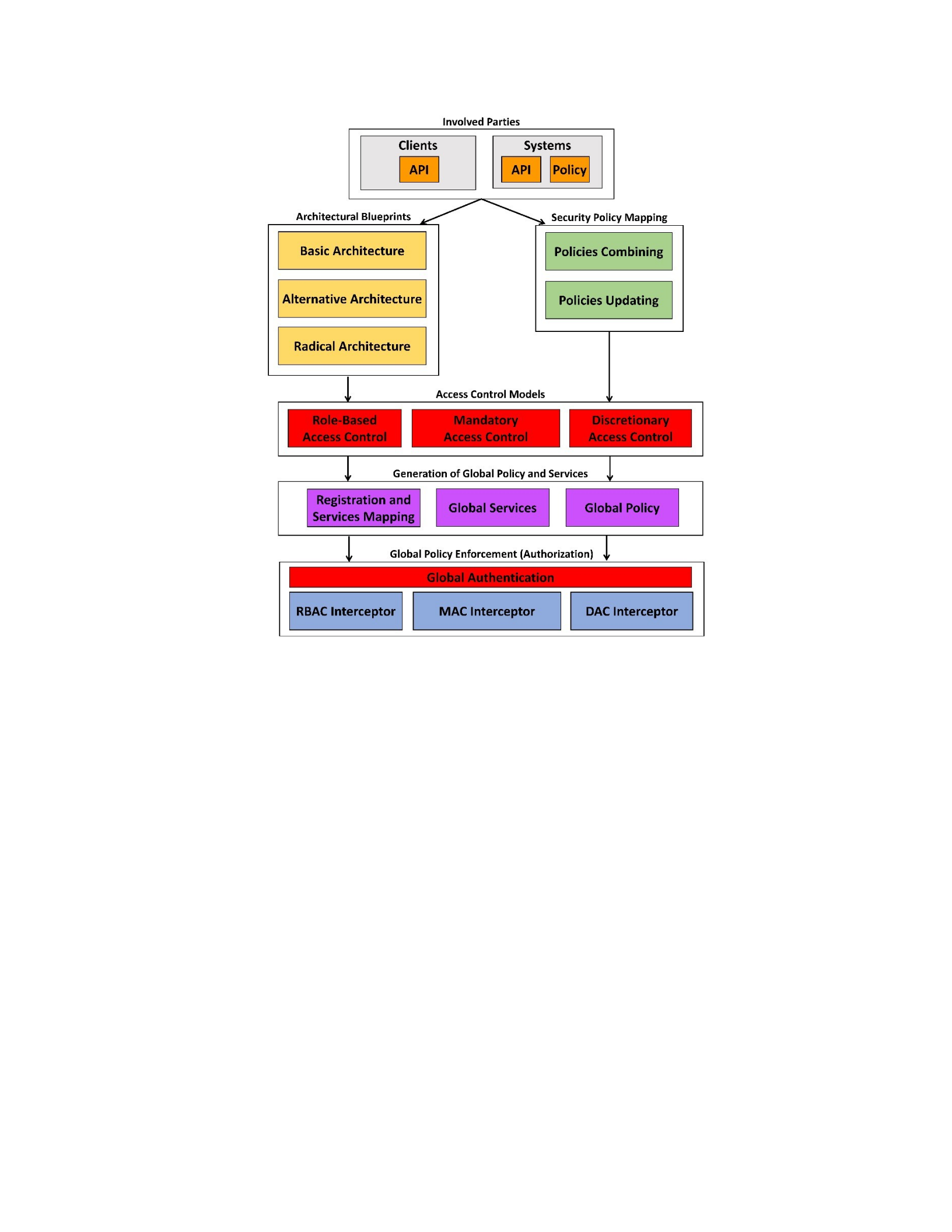
Figure 1.2. A Component-Level View of the presented FSICC.
The selection of an architectural blueprints option is determined based on four factors that
describe the situation of a client or system: the overall architecture of the application (i.e.,
onetier, two-tier, and three-tier architecture); the involved technologies that can be used to
develop the application (i.e., RESTful APIs, programmatic APIs, database API); the source code
availability of the application, APIs, server code, or database; and, the allowable access to system
sources (RESTful APIs, programmatic APIs). Based on the output of the Architectural Blueprints
component and after a system has registered at the Integration Layer, the security engineer of
FSICC can establish the global API (services) in a two-step process. First, the security engineer
creates a set of common services from the integration layer API, utilizing the

Services Mapping process using the Generation of Global Policy and Services component in
Figure 1.2, where each system in the global API is configured to send/receive requests to/from
the integration layer API of the appropriate system. Second, each client can configure its
integration layer API to send/receive requests to/from the Global API. Based on the output of the
Security Policy Mapping component, the security engineer utilizes the Access Control Models
component to define the security policies of systems that was shown at the bottom of Figure 1.1
and in the process to establish the global security policy that was shown in the middle of Figure
1.1. The security engineer can develop the global security policy by: creating global roles in
which each global role can be authorized to a subset of the global services and creating new users
(from clients) in which each global user can be assigned to one or more global roles (RBAC);
assigning classification for each global service, and assigning clearance for each global user with
read and write properties (MAC); and, enabling role or service delegation from one to another
global users (DAC).
The resulting global services (API) and global security policy comprise the Generation of
Global Policy and Services component, shown in the middle of Figure 1.2. After establishing the
global security policy, a number of security interceptors can be created to enforce the global
security policy on the users’ access requests, after such users have been authenticated. A security
interceptor can be defined as a programmatic mechanism that is able to intercept a service call
from a client application to an API (service) in order to perform appropriate security enforcement
checks. The Global Policy Enforcement component shown at the bottom of Figure 1.2 refers to
the RBAC/MAC/DAC interceptors box that was shown in the middle of Figure 1.1, consists of
four boxes. The Global Authentication box is utilized to verify the claimed credentials, ID and
security token, that a user (client) provided is correct or not. The RBAC Interceptor box provides

the ability to allow/deny a global user with a global role from accessing a specific global service.
The MAC Interceptor box provides the ability to allow/deny a global user with a clearance from
accessing a specific global service. The DAC Interceptor box provides the ability to allow/deny a
global user (with a delegated global role, global service, or global clearance) from accessing a
specific global service. Collectively, FSICC as presented in Figure 1.2, represents a set of
interacting components that allows from a transition to isolated clients and systems being able to
join and utilize a global environment that provides a single common way to access services.
1.5 Research Objectives and Expected Contribution
In this section, we discuss the research objectives and expected contributions of this
dissertation. Since the component-level view of the presented FSICC in Figure 1.2 does not
provide an adequate representation of the underlying models, concepts, and research of FSICC
for the dissertation, we supplement Figure 1.2 with Figure 1.3 which provides a high-level view
of the research of FSICC as discussed in Section 1.4, organizing and grouping the components of
Figure 1.2 into a perspective that identifies the research areas and foci of the dissertation. Figure
1.3 has horizontal boxes that contain the main research foci of this dissertation and vertical boxes
that span across multiple foci.
The five horizontal boxes are: Architectural Blueprints that contain the different options for
architectural option for connecting clients and systems with FSICC that was shown in the upper
left portion of Figure 1.2; Unified Cloud Computing Access Control Model with boxes for
Schema Definitions, Enterprise Definitions, Policy Definitions, FSICC Definitions, and
Intercepting Definitions; Access Control Models for the ability to control services via RBAC,
MAC, and DAC as discussed for FSICC's security requirements in Section 1.3 and that was

shown in the middle of Figure 1.2; GSP (Global Security Policy) Generation and GAPI (Global
API) Generation for generating the security policy from multiple systems to make global APIs
available to clients what’s showing in the lower portion of Figure 1.2; and, Global Security
Policy and Global API Utilization and Security Enforcement that utilizes security interceptors
that was shown in the bottom of Figure 1.2 to allow/deny clients from access global services of
FSICC. The security requirements introduced in Section 1.3 are represented by the upper right
vertical box SECURITY REQUIREMENTS in Figure 1.3 that spans two horizontal boxes:
Unified Cloud Computing Access Control Model and Access Control Models. The cloud
computing capabilities introduced in Section 1.3 are represented by the lower right vertical box
CLOUD COMPUTING CAPABILITIES in Figure 1.3 that spans two horizontal boxes: Global
Security Policy and Global API Generation and Global Security Policy and Global API
Utilization and Security Enforcement.
From a research perspective, the presented Framework for Secure and Interoperable Cloud
Computing that was shown in Figure 1.2 has the following four expected contributions (EC-A,
EC-B, EC-C, and EC-D) which are presented and discussed using the security requirements and
cloud computing capabilities of Section 1.3 and Figures 1.2 and 1.3. The expected contributions
are also highlighted in the horizontal and vertical boxes of Figure 1.3.
EC-A: Architectural Blueprints for Supporting FSICC: This contribution facilitates
the interoperability and information exchange of clients and systems and presents a
collection of three architectural blueprints (i.e., Basic Architecture, Alternative
Architecture, and Radical Architecture) for the design and development of integration
framework (IFMWK) servers utilizing a standard integration framework (e.g., FHIR in

the healthcare domain) that enable the integration between systems with applications.
This was shown in the upper half (left) of Figure 1.2. The architectural blueprints are
represented as the first horizontal box Architectural Blueprints in Figure 1.3 and includes
three main boxes for: Interoperability Issues, Integration Options, and Integration
Blueprints. Each blueprint is based on the location that IFMWK servers can be placed
with respect to the components of the application (UI, API, Server) or a HIT system in
order to define and design the necessary infrastructure to facilitate the exchange of
information via IFMWK.
EC-B: An Integrated RBAC, MAC, and DAC Model for Cloud Computing: This
contribution involves a Unified Cloud Computing Access Control model (UCCACM) for
the FSICC that provides a single view of global services to applications (i.e., clients) and
allows those global services to be authorized according to RBAC, MAC, and DAC
policies. The UCCAC model is represented by the second horizontal box Unified Cloud
Computing Access Control Model in Figure 1.3 that includes five main boxes for:
Schema Definitions, Enterprise Definitions, Policy Definitions, FSICC Definitions, and
Intercepting Definitions. The contribution will include a set of formal definitions for
RBAC, MAC, and DAC access control models that specifies, in detail, the way that: each
system can register its services and security policies; and, a security engineer can define a
set of global RBAC, MAC, and/or DAC policies on a unified set of global cloud services.
The UCCAC model basically provides formal definitions for the main components of
Figure 1.2.

EC-C: Security Mapping/Enforcement Algorithms and SSEP: The Security
Mapping/Enforcement Algorithms aspect of this expected contribution is realized within
the horizontal box near the bottom of Figure 1.3, labeled GSP (Global Security Policy)
Generation and GAPI (Global API) Generation which includes Security Policies and
Services Registration, Global Services Generation, and Global Security Policy
Generation. This SOA-based security engineering process (SSEP) aspect of this expected
contribution for FSICC that can be utilized to combine security policies (that can be
RBAC, MAC or DAC) from different systems into one global security policy, in which
SSEP also includes a process for security enforcement code generation. This was shown
in the upper right half of Figure 1.2. A portion of the SSEP is human assisted in order to
reconcile naming issues of roles, mapping sensitivity levels, etc., that are integrated from
multiple clients and systems. Once the policies are successfully mapped, all of the
security enforcement code can be automatically generated by algorithms. The SSEP for
FSICC is represented by the left vertical box SOA-BASED SECURITY ENGINEERING in
Figure 1.3 that spans all of the five horizontal boxes: Architectural Blueprints, Unified
Cloud Computing Access Control Model, Access Control Models, Global Security Policy
and Global API Generation, and Global Security Policy and Global API Utilization and
Security Enforcement.
EC-D: Dynamic Enforcement via Intercepting Process: This contribution involves a
set of programmatic mechanisms that are able to intercept a service call from a client app
to an API in order to perform appropriate security enforcement checks. This was shown

in the bottom of Figure 1.2. In Figure 1.3, these security interceptors are represented
within the last horizontal box Global Security Policy and Global API Utilization and
Security Enforcement in Figure 1.3, and the Security Enforcement via Interceptors box in
Figure 1.2. Interceptors include: a RBAC Interceptor that is able to determine at runtime
if the requested API call on a global service can be executed for a specific user with a
specific role; a MAC Interceptor that is able to determine at runtime if the requested API
call on a global service can be executed for a user with a clearance and limited by if the
services is read or write; and a DAC Interceptor that is able to determine at runtime if the
requested API call on a global service can be executed for a specific user with a delegated
role/service/clearance.
Throughout the remainder of the dissertation, these expected contributions (EC-A, EC-B, EC-C,
and EC-D) will be high-lighted when relevant.
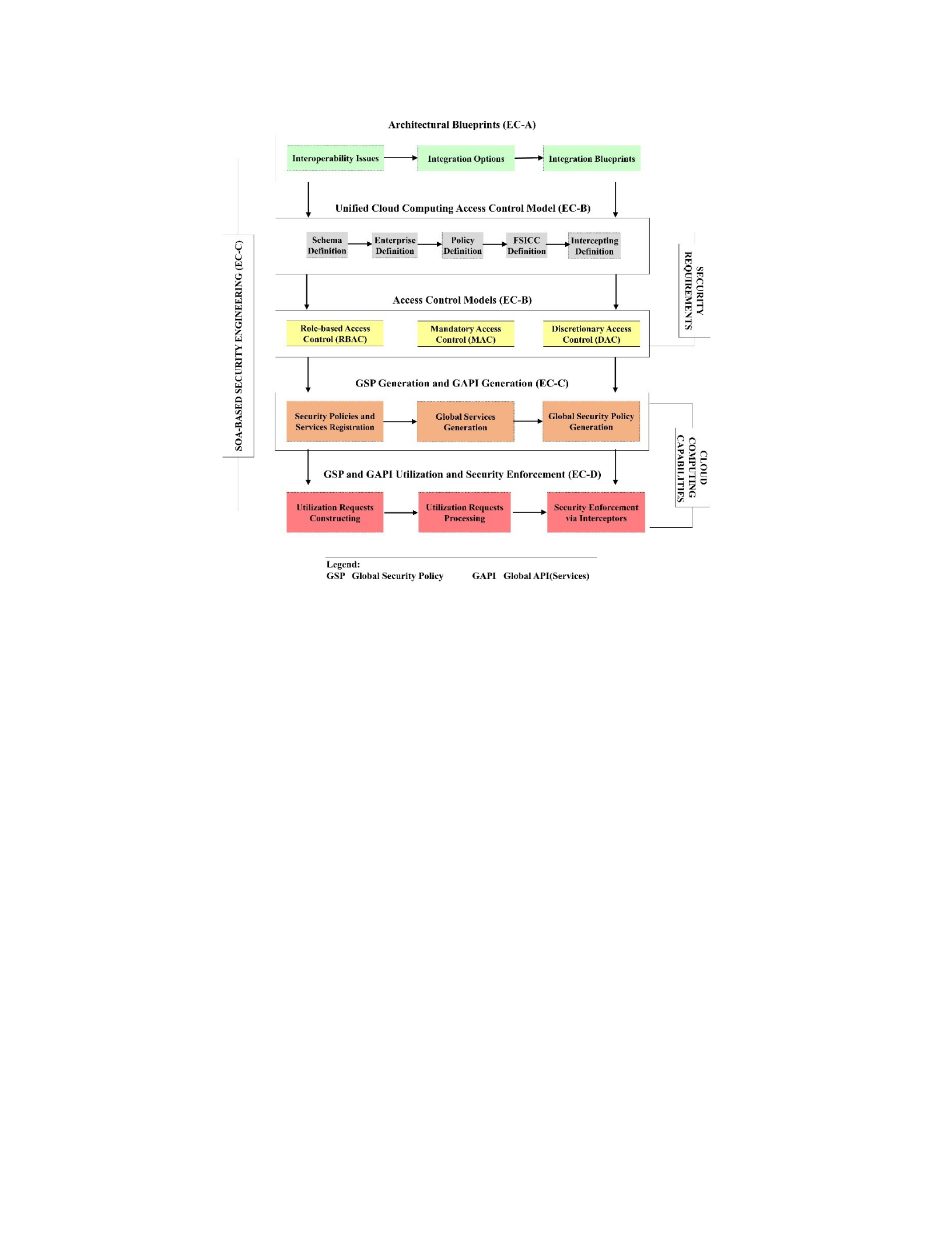
Figure 1.3. High-Level View of FSICC Research Areas and Foci.
1.6 Research Progress to Date
In support of the presented Framework for Secure and Interoperable Cloud Computing, a
number of articles have been published:
•Baihan, M., Sánchez, Y., Shao, X., Gilman, C., Demurjian, S., & Agresta, T. (2018). A
Blueprint for Designing and Developing M-Health Applications for Diverse Stakeholders
Utilizing FHIR. In R. Rajkumar (Ed.), Contemporary Applications of Mobile Computing
in Healthcare Settings (pp. 85-124). Hershey, PA: IGI Global.
•Baihan, M., and Demurjian, S. (2017). A Framework for Secure and Interoperable Cloud
Computing. In Research Advances in Cloud Computing, S. Chaudhary (ed.), Springer.
•Baihan, M., Demurjian, S., Rivera Sánchez, Y., Toris, A., Franzis, A., Onofrio, A.,

Cheng, B., and Agresta, T. (2017). Role-Based Access Control for Cloud Computing
Realized within HAPI FHIR. Proceedings of 16th International Conference on
WWW/INTERNET 2017 (ICWI 2017), October 2017.
Other published or submitted articles:
● Rivera Sánchez, Y., Demurjian, S., and Baihan, M. (2017). Achieving RBAC & MAC on
RESTful APIs for Mobile Apps using FHIR. In The 5th IEEE International Conference
on Mobile Cloud Computing, Services, and Engineering.
●Ziminski, T. B., Demurjian, S. A., Sanzi, E., Baihan, M., and Agresta, T. (2017). An
Architectural Solution for Health Information Exchange. In International Journal of
User-Driven Healthcare (IJUDH), 6(1), 65-103.
● Rivera Sánchez, Y., Demurjian, S., and Baihan, M. (2017). A Service-Based RBAC &
MAC Approach Incorporated into the Fast Healthcare Interoperable Resources (FHIR)
standard. Submitted to The Digital Communications and Networks Journal, special issue
on The Security, Privacy, and Digital Forensics of Mobile Networks and Mobile Cloud.
1.7 Dissertation Outline
The remainder of the dissertation has seven chapters. In Chapter 2, we review background on:
cloud computing and its main technologies; RBAC, MAC, and DAC models that are utilized to
enforce authorization on cloud services; application programming interfaces (APIs); and, the Fast
Health Interoperable Resources (FHIR) standard and its HAPI FHIR implementation. In Chapter
3, we present and explain four security requirements and three cloud computing capabilities for
FSICC that both simplifies and enables client access via global resources via standardized system

APIs. Chapter 4 defines a Unified Cloud Computing Access Control model (UCCACM) for
RBAC, MAC, and DAC access control for a cloud setting; this addresses Contribution EC-B: An
Integrated RBAC, MAC, and DAC Model for Cloud
Computing. In Chapter 5, we present a set of blueprints for the design and development of
IFMWK servers in which an application can interact with multiple HIT systems via IFMWK
through the design, implementation, and usage of IFMWK servers. The architectural blueprints
consist of three main architectural integration options: Basic Architecture, Alternative
Architecture, and Radical Architecture; this addresses Contribution EC-A: Architectural
Blueprints for Supporting FSICC. Chapter 6 has two main parts. The first part presents a set of
algorithms for generating the global security policy of FSICC; this partially addresses
Contribution EC-C: Security Mapping/Enforcement Algorithms and SSEP by focusing on
Security Mapping/Enforcement Algorithms. The second part introduces and discusses three
security interceptors for RBAC, MAC, and DAC via a number of checks and an algorithmic
approach for each interceptor; this addresses Contribution EC-D: Dynamic Enforcement via
Intercepting Process. Chapter 7 introduces and discusses an SOA-based security engineering
process for FSICC that is intended to help security engineers of systems and clients, on one side,
and the security engineer of FSICC, on the other side, to establish and maintain secure
interoperable services via RBAC, MAC, and DAC; this partially addresses Contribution EC-C:
Security Mapping/Enforcement Algorithms and SSEP by focusing on SSEP. Finally, Chapter 8
summarizes the contributions of the dissertation and discusses future work.

Chapter 2 Background
This chapter provides background material on the main concepts and topics that support the
discussion and explanation in the remainder of this dissertation. Section 2.1 presents the cloud
computing concept and underlying application programming interfaces (APIs), and discusses the
main technologies behind cloud computing with an emphasis on the serviceoriented architecture
(SOA) technology that underlies the cloud service model. Section 2.2 reviews the three classic
access control approaches: role-based access control (RBAC)
(Ferraiolo, Sandhu, Gavrila, Kuhn, & Chandramouli, 2001), discretionary access control (DAC)
(Dittrich, Härtig, & Pfefferle, 1988), and mandatory access control (MAC) (Bell & La Padula,
1976). Section 2.3 introduces and explains the Fast Health Interoperable Resources (FHIR)
standard with an emphasis on the FHIR Resources and reviews the HL7 Application
Programming Interface FHIR (HAPI-FHIR) which is one popular reference implementation of
the FHIR standard. Section 2.4 introduces and presents a sample healthcare scenario utilized
throughout this dissertation.
2.1 Cloud Computing and APIs
Cloud computing has emerged as a de facto approach throughout society, commercial,
governmental sectors, and research/academic communities. The National Institute of
Standards and Technology (NIST) (Mell & Grance, 2011) defines: “Cloud computing is a model
for enabling convenient, on-demand network access to a shared pool of configurable computing
resources that can be rapidly provisioned and released with minimal management effort or
service provider interaction.” Historically, cloud computing emerged from the evolution of
existing technologies (Zhang, Cheng, & Boutaba, 2010), such as service-oriented architecture,

that are combined in a certain way to provide a new business model. Serviceoriented architecture
(SOA) (IBM, 2015) is a model for designing systems in which the focus is around offering
services for different consumers. An SOA implementation, such as the web services standard,
could adopt the eXtensible Markup Language (XML) as an SOA approach that enables systems
to provide and consume services in a common manner without the need to use a specific
programming language or operating system.
This facilitates services integration. Service suppliers define and publish services for use by
consumers. Cloud services are provided and delivered based on the cloud service model
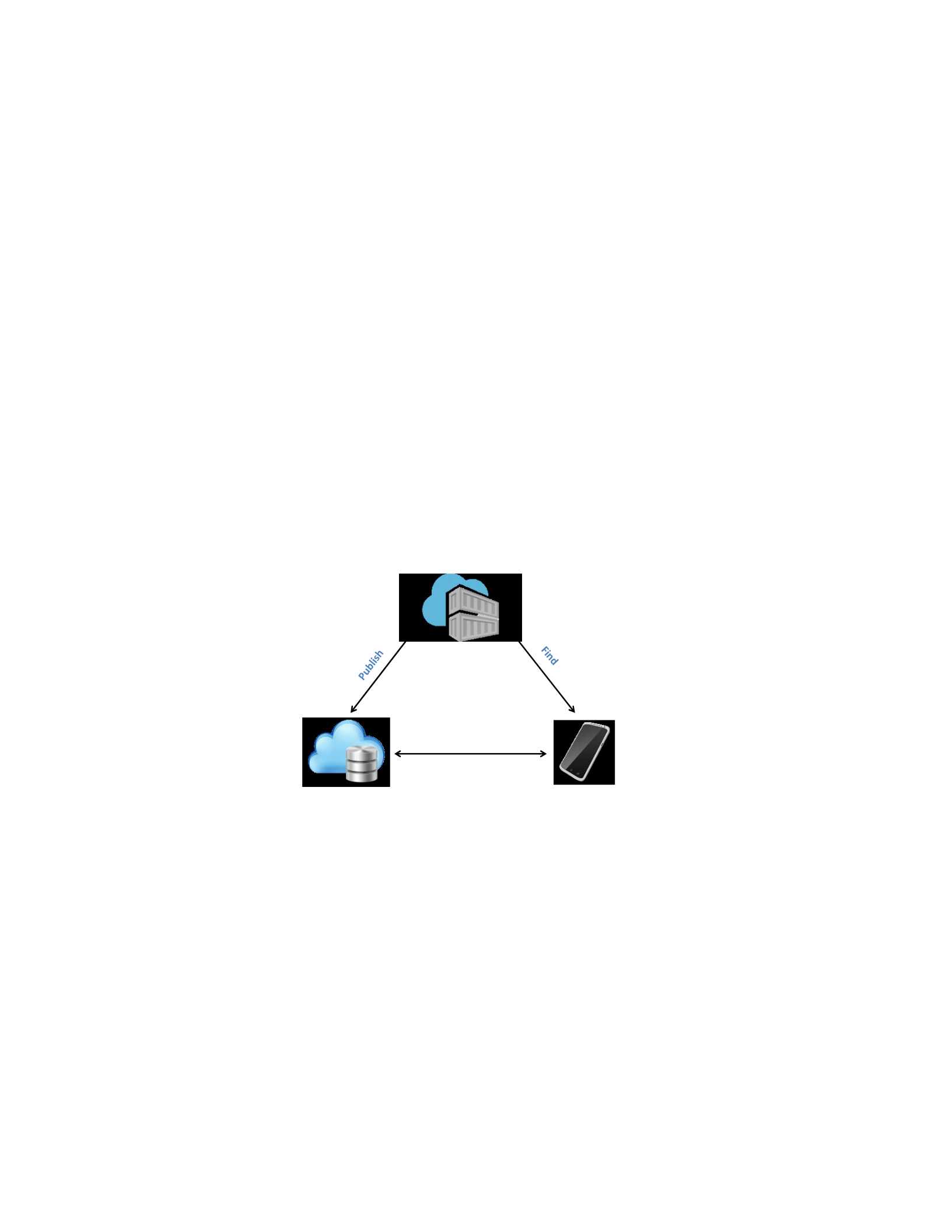
(Microsoft.com, 2016) by leveraging concepts from SOA. In the cloud service model in Figure
2.1, there are three main components: Cloud Service Registry, Cloud Service Supplier, and Cloud
Service Consumer. The Cloud Service Registry component maintains information on available
cloud services. The Cloud Service Supplier component publishes services to the Cloud Service
Registry. The Cloud Service Consumer component discovers services from Cloud Service
Registry and consumes them. Cloud services are the APIs that define the way that cloud
consumers can access and utilize cloud-computing resources such as software.
Cloud computing utilizes an Application Programming Interface (API) to support the
definition of services. An API requires a set of inputs via an HTTP request to generate a response
in a specific format such as the Extensible Markup Language (XML), the JavaScript Object
Notation (JSON), etc., based on the inputs. In cloud computing, the cloud services are the APIs
that define the way that cloud consumers can access and utilize cloud-computing resources such
as software. Some benefits of creating an API are: (1) data can be transferred from one system to
another system easily and smoothly; (2) an API can be called and processed by almost any
programming language that can be different from the programming language of the actual system
implementation; and, (3) an API can be utilized to encourage external developers to add new
features or to enhance current features of a system. An API can be designed using web services
such as: Representational State Transfer (REST) (Fielding, 2000), Simple Object Access Protocol
(SOAP) (Microsoft Inc., 2016), etc. Any API designed based using the REST protocol is called a
RESTful API, which is defined as a set of definitions for methods of the Back-end system. A
RESTful API utilizes a Hypertext Transfer Protocol (HTTP) request to interact with the API
consumers and the back-end system (Rouse, 2014). RESTful requests are frequently referred to
as CRUD, which is short for Create, Read, Update, and Delete functions. CRUD operations from
an HTTP perspective are typically defined as: GET to retrieves data; PUT or
POST to insert data; POST, PUT, or PATCH to update data; and, DELETE to remove data.
RESTful APIs have become a dominant choice for designing and implementing cloud services.
Figure 2.1. Cloud Service Model.
2.2 Access Control Models
Access control models have gained wide acceptance in computing, traditionally in controlling
access to data in objects that are in a database or a repository. The three classic approaches are:
role-based access control (RBAC) (Ferraiolo, Sandhu, Gavrila, Kuhn, & Chandramouli, 2001),
discretionary access control (DAC) (Dittrich, Härtig, & Pfefferle, 1988), and mandatory access
Cloud Service
Registry
Cloud Service
Supplier
Cloud Service
Consumer
Bind

control (MAC) (Bell & La Padula, 1976). RBAC provides an efficient way to manage
consumers, users of a system, by utilizing the concept of role in which each role can be
authorized to access a sub-set of the available cloud services and each consumer is assigned one
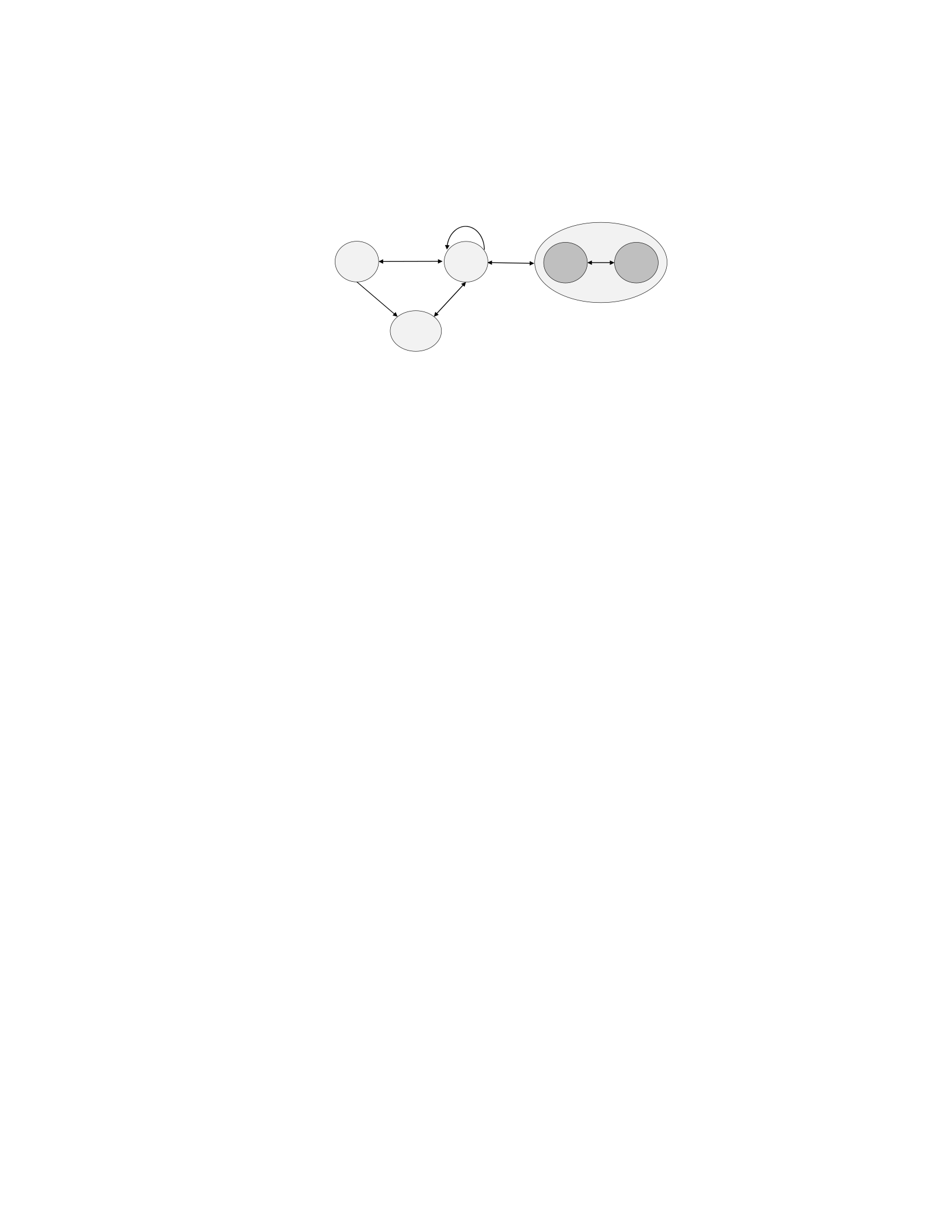
or more suitable roles. The RBAC model as shown in Figure 2.2 consists of three main
components: elements that describe the different components; constraints that can be defined on
the elements; and, relations that exist between the various elements.
There are five main elements in RBAC: objects that represent functionality for an application;
operations that are defined on objects; permissions that are the allowed operations on the
different objects; roles that represent a set of responsibilities for a user of the application to
capture the defined permissions; and, users that are assigned to a role during a session of an
application. RBAC supports a number of constraints that can be defined to restrict a user playing
a specific role. Finally, RBAC elements can be organized into relations: a role-user relation to
assign users to roles; a role-permission relation to assign permissions to roles; a role-session
relation to assign sessions to roles; a user-session relation to assign users to sessions; an
operation-object relation to assign objects to operations; and, a role-role relation to define a role
hierarchy. Moreover, the role-role relations form a partial order and are represented using an isa
role hierarchy based on generalization (Ferraiolo, Sandhu, Gavrila, Kuhn, & Chandramouli,
2001). That is, any role that is located higher up in the hierarchy, is a more general role than roles
lower in the role hierarchy. As a result, a non-root role inherits all of the permissions authorized
to the roles above, namely, the ancestors. In addition, some roles in the role hierarchy are abstract
roles in which no users will be assigned to such roles. For example, in healthcare, a physician
role can be at a higher level than a private physician role, which inherits all of the permissions
authorized to the physician role; in such a role hierarchy, the physician role is a more general
role.
Figure 2.2. RBAC Model.
When cloud services need to access very sensitive information such as patient data that needs
to be more strongly controlled than other parts of the patient data, MAC can be employed to
control access to services using the concept of a sensitivity level, which is a security label that
can be assigned to an object or a user to indicate the importance of such service or user. In MAC,
sensitivity levels are assigned to subjects (clearance) and objects (classification) with the
permissions for the subject to read and/or write an object dependent on the relationship between
clearance (assigned to users) and classifications (assigned to objects). MAC typically is
modeled using four sensitivity levels which are hierarchically ordered from most to least secure:
Top Secret (TS) < Secret (S) < Confidential (C) < Unclassified (U); this is referred to as the
multilevel security model (MLS). These terms are defined in the U.S. classification of
information systems in a Presidential Executive Order (National Archives, 1982):
“(1) "Top Secret" shall be applied to information, the unauthorized disclosure of which
reasonably could be expected to cause exceptionally grave damage to the national security.
(2) "Secret" shall be applied to information, the unauthorized disclosure of which
reasonably could be expected to cause serious damage to the national security.
Roles
Users OBS
OPS
PRMS
Sessions
UA
Session_roles
User_sessions
PA
RR

(3) "Confidential" shall be applied to information, the unauthorized disclosure of which
reasonably could be expected to cause damage to the national security.”
In MAC, the central authority maintains a classification (CLS) for each object and a clearance
(CLR) for each user in the system. The MAC model (Bell & La Padula, 1976) also has a set of
properties, namely, Simple Security (SS), Simple Integrity (SI), Liberal* (L*), and Strict* (S*)
that has both Read and Write capabilities. Such properties are defined to determine under which
conditions a user with a CLR level can read or write a given data item with a CLS level. First,
the SS property (or read-down, no read-up) is the permission to read an object that has an equal
or lower CLS level. That is, a user is allowed to read an object with a CLS level equal to or lower
than their CLR level, but not those objects with a higher CLS level. Second, the SI property (or
write-down, no write-up) is the permission to write an object that has an equal or lower CLS
levels. That is, a user can write an object of equal or lower CLS level when compared to their
CLR level, but not to those objects with a higher CLS levels. Third, the L* property (or write-up,
no write-down) is the permission to write an object that has an equal or greater CLS level (the
opposite of SI). Forth, S* Write property (or write equal) is the permission to write an object that
only has an equal CLS level. Finally, the S* Read property (or read equal) is the permission to
read an object that only has an equal CLS level. From a definition and management perspective,
an Security engineer of a system would set the CLR level of users following the predefined
sensitivity levels (e.g., TS, S, C, and U) to establish the levels for both users and objects. These
levels are then augmented on a user-by-user basis by assigning the ability to read an object (via
SS or S* Read properties) and the ability to write an object (via SI, L*, or S* Write properties).
To explain the read/write properties, assume that there is an object O1 with a confidential
classification; an object O2 with a top secret classification; a user U1 with a top secret clearance,

with SS read property and SI write property chosen for that user. Assume another user U2 with a
secret clearance with SS read property and SI write property chosen for this user. In this setting,
U1 can read and write O1 and O2, while U2 can only read and write O1, as shown in Figure 2.3.
Clear: TSClass: C
Clear: SClass: TS
Figure 2.3. An Example of MAC.
However, the four sensitivity levels typically used in MAC are insufficient to classify data in
some complex areas such as healthcare. For this reason, a number of healthcare-based sensitivity
level sets have been proposed in the literature. Two main works are: the HL7 v3 standard
confidentiality labels (Health Level 7., 2014); and a proposed healthcare multi-level security
labeling system (Demurjian, Sanzi, Agresta, & Yasnoff, 2018). In the first work, the HL7
organization introduced the HL7 v3 standard which contains a definition for a set of
confidentiality labels that is defined to accurately classify healthcare related data. Specifically,
the HL7 v3 standard defines six confidentiality labels: U – unrestricted, L – low, M – moderate,
N – normal, R – restricted, and V – very restricted; these six levels replace the four traditional
sensitivity levels of MAC. Figure 2.4 presents the HL7 v3 confidentiality labels with a definition
and examples for each confidentiality label, taken from
(http://www.hl7.org/documentcenter/public_temp_DFF235EF-1C23-BA17-
0CB382A77F4391FB/standards/vocabulary/vocabulary_tables/infrastructure/vocabulary/
vs_Conf identiality.html). Note that these confidentiality labels indicate the type of healthcare
related data that needs to be protected and are different from the typical four sensitivity levels of
MAC.
U1O1
O2
U2
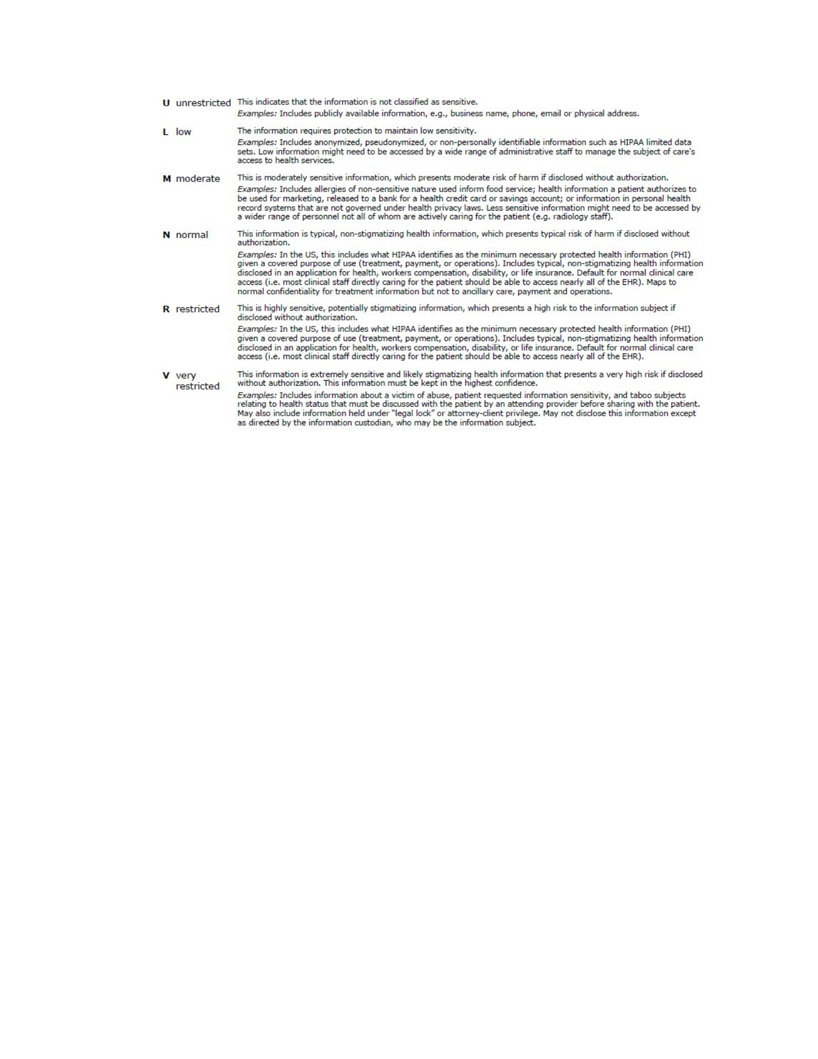
Figure 2.4. Confidentiality Labels from HL7 Release 3 Standard.
In the second work, Demurjian et al., (Demurjian, Sanzi, Agresta, & Yasnoff, 2018) proposed
a multi-level security labeling system for healthcare domain which has five healthcare
sensitivity levels (0-4) and within each level there are different categories of data that will be
given to different users based on their need as Figure 2.5 shows, where Level 0 is the least
secure, while Level 4 is the most secure. Specifically:
Level 0 (Basic Information) is public data available to anyone without control in
which data in this level can be categorized into: 0-DM for basic demographics such as
city and state of residence, 0-C for general health condition, and 0-FT for information
related to tracking fitness data.
Level 1 (Medical History Data) contains data that has some restrictions in which data
in this level can be categorized into: 1-DM for detailed demographic data, 1-MHx for
history of the patient and his/her family, 1-FHx for more sensitive patient-collected
fitness data, 1-IM for immunizations, and 1-MH-Hx for mental health history of the

patient.
Level 2 (Summary Clinical Data) contains clinical data in which data in this level can
be categorized into: 2-Rx for prescription, 2-OTC for over-the-counter medications,
2ALL for allergies, 2-Dx for medical diagnoses and problem list, 2-PL for plan for
treatment or other related instructions, 2-MH-Dx for mental health, separate medical
diagnoses and problem list, and 2-MH-PL for plan for treatment or other related
instructions.
Level 3 (Detailed Clinical Data) is for use by medical providers in which data in this
level can be categorized into: 3-RP for reports from imaging studies (CT Scans, MRIs,
X-Rays, etc.), 3-IM for the images from the studies, 3-EN for detailed information on
each medical visit, 3-LB for laboratory tests ordered, dates, and results including
surveillance data, 3-MH-EN for information about mental health encounters, 3-SR for
surveillance data, and 3-FT for clinical data from fitness devices.
Level 4 (Sensitive Clinical Data) contains sensitive information on a patient that is
used by medical specialists in which data in this level can be categorized into: 4-G for
data on genetics, 4-SA for substance abuse, 4-MH for mental health psychotherapy
notes, 4-RH for reproductive health, and 4-DV for domestic violence.
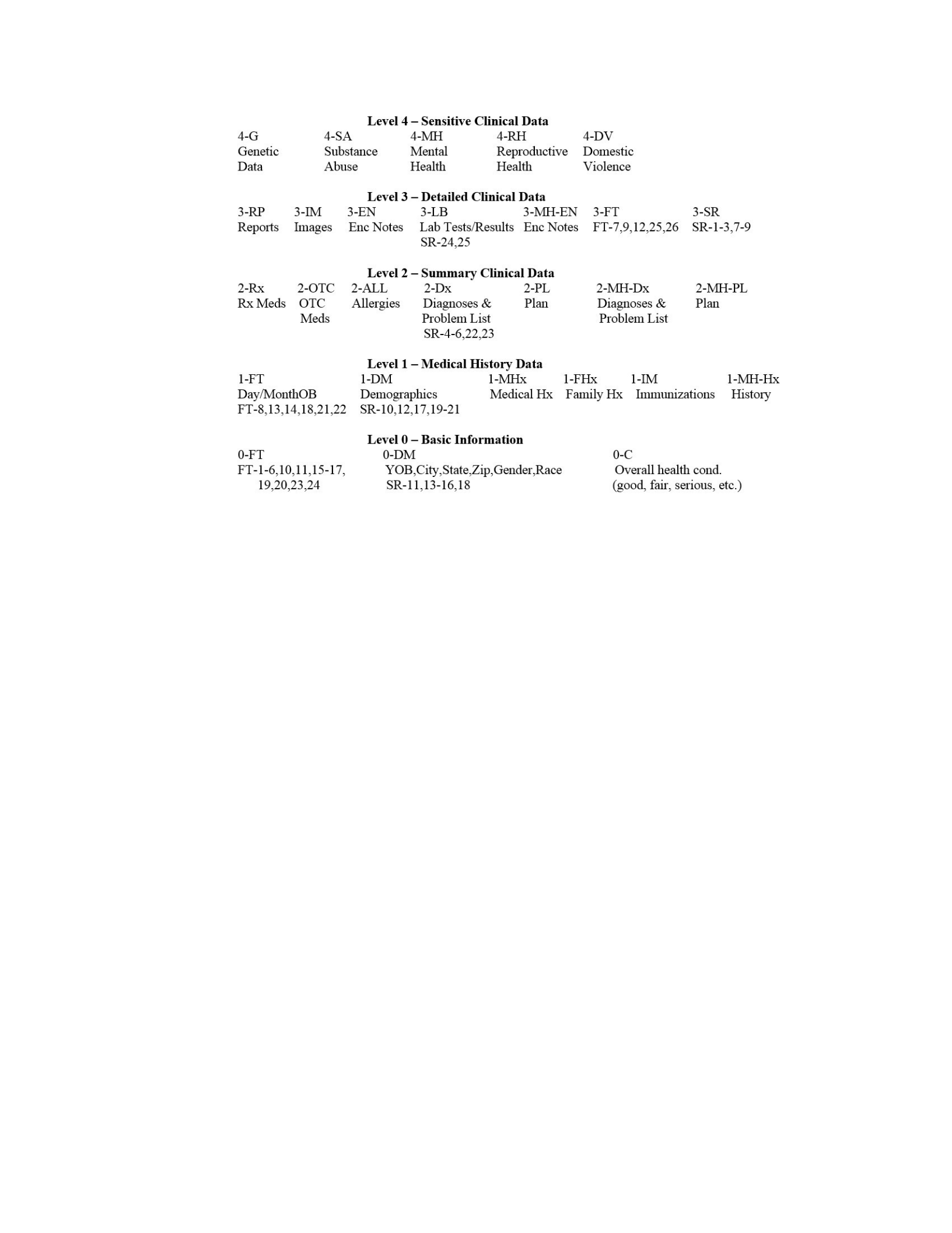
Figure 2.5. A Multi-Level Healthcare Sensitivity Levels.
DAC can be defined as an access control mechanism that can restrict operations (e.g., read,
write, execute) on objects (or services) based on the identity of subjects (users) and/or groups to
which they belong, as shown in a Figure 2.6. The word “discretionary” in DAC indicates that a
subject with a certain access permission is capable of passing that permission on to any other
subject so that the delegated user may utilize the delegated permission. A subject is also called an
original user which means that the user was assigned the role directly in the security definition
process. A role that is assigned to an original user is referred to as an original role, in such an
original role has original role permissions. An original user may also be assigned a clearance
level if they are assigned mandatory access capabilities which is reference to as an original
clearance. An original user may have delegation of authority which allows the original user to
pass on the original role to a delegated user who acquires all of the capabilities of the original
uses role. When the original role is passed to the delegated user, is it is referred to as the

delegated role of that delegated user. The delegated role in turn has delegated role permissions,
and if the original user had an original clearance, it too could be passed to the delegated user as a
delegated clearance. Two other important concepts for DAC are delegation authority and pass on
delegation of authority. Delegation authority is the authority given to an original user that allows
the original user to delegate his or her role to a delegated user. Pass-on delegation authority,
PODA, is the authority given to an original user or delegated user that allows that user to
delegate on a useful set of definitions and rules for delegation which underlie a proposed
delegation language (Zhang, L., Ahn, J., & Chu, T., 2001).
In a cloud computing setting, DAC can offer the ability of a consumer of the cloud services to
enable another consumer to utilize all or a sub-set of the consumer’s authorized cloud services,
that are assigned based a role or a clearance, through a delegation of authority. DAC, as shown in
Figure 2.6, utilizes the concept of delegation to pass privileges among users to delegate both
authority and permissions to another user. For example, in healthcare, a physician Charles that is
leaving the office on the weekend could delegate his responsibilities (e.g., patients) to the on-call
physician Lois who will be covering any queries from patients. Charles can delegate all of his
permissions and also the ability to further delegate those permissions beyond the original scope.
For example, if the on-call physician Lois has to attend to an emergency, she could then employ
user-directed delegation to delegate the permissions passed to her by Charles to another user
Thomas. Administrative-directed delegation has a security engineer to control delegation.
Figure 2.6. DAC Model.
Users OBS
OPS
PRMS
Delegate

Traditionally, RBAC, DAC, and MAC models define permissions over objects and operations
of a system. However, the work in this dissertation is focused on a Framework for Secure and
Interoperable Cloud Computing (FSICC) which involves the definition of Global Services and
the need to define security policies that allow the ability to determine which user can access
which service at which times. The work in this dissertation is very cloud-computing focused with
an emphasis on services, and since we are interested in supporting Access Control in FSICC the
RBAC, DAC, and MAC models need to be upgraded, extended, and modified so that
permissions can be defined against cloud services. Such an extension to access control will
provide us with the ability to: specify which role can access which cloud service at which time
and under which situation thereby supporting RBAC; define a classification of each cloud service
and a clearance for each user/client in order to control which Services can be accessed thereby
supporting MAC; and, delegate a cloud service from one user to another user thereby supporting
DAC. This allows the FSICC to authorize a mobile, web, and desktop applications, by
roles/clearance, to access cloud services.
2.3 FHIR and HAPI FHIR
The Fast Health Interoperable Resources (FHIR) is a health integration standard developed by
the Health Level Seven International (HL7) organization (Health Level 7, Fast Health
Interoperable Resources, 2016). FHIR is primarily structured around the concept of FHIR
resources (Health Level 7, Fast Health Interoperable Resources list, 2016) which are the data
elements and associated RESTful APIs that can be leveraged for exchanging healthcare
information, particularly between mobile applications and HIT systems. FHIR Resources, the
main building block in FHIR, can hold any type of information that FHIR deals with to be
exchanged from one health information technology system to another via RESTful API services

that utilize with an XML or JSON format. Resources are broadly classified into different
categories: Clinical Findings; Patient Problems, Allergies, and Adverse Events; Patient History;
Suggested Physician Orders; and, Interdisciplinary Care Planning. To illustrate, sample FHIR
resources from the 119 currently defined (and always increasing) are: the Practitioner resource to
track medical providers (physicians, nurses, office staff, etc.); the Patient resource can track
demographic data on patients; the RelatedPerson resource to track parents/guardians; the
FamilyMemberHistory for basic information on a family medical history; the Condition resource
to track the relevant medical conditions; the Observations resource to track symptoms, and other
medical observations; and, the Encounter/EpisodeOfCare resources to track the different times
that changes to patient data occur based on a visit (Encounter) or action at the visit
(EpisodeofCare).
FHIR Resources can be utilized by HIT systems and applications for different purposes. For
example, an mHealth application may use the Patient resource to store and exchange information
about patients back and forth with different HIT systems. All FHIR resources have five main
properties in common: a unique URL for identification purposes; common metadata; a human
readable section; a number of predefined data elements; and, an extension element that enables a
system to add new data elements. FHIR provides four main equivalent representation formats:
the Unified Modeling Language (UML) format for a diagrammatic representation of the
resource; an XML schema that is subset of the HL7 schema for the resource; a JSON
representation to facilitate a programmatic exchange via a RESTful APP; and, a Turtle resource
definition format (RDF) to assist the process of bridging between operational data exchange
within formal knowledge processing systems. Figure 2.7 shows an example of a FHIR Patient
resource represented in the JSON format. FHIR supports a number of REST API services to

enable a system to retrieve and modify data in the Resources. The main five services are: Create
to add a new instance of a resource; Read to retrieve an existing instance of a resource; Update
to manipulate data in an existing instance of a resource; Delete to remove an existing instance of
a resource; and, Search to retrieve all existing instances of a resource. The first four services are
similar to CRUD, while the fifth service for search is intended to allow repositories to be
accessed.
{ "resourceType": "Patient",
"id" : "1",
"meta" : { "versionId" : "1", }
"text": { "status": "generated", },
"identifier": [ { "label": "OpenEMR",
"system": "http://www.healthorg.org/openemr",
"value": "10“ } ],
"name": [ {"family": "Levin",
"given": "John" } ],
"gender": {"text": "Male" }, "birthDate":
"1985-02-12“ }
Figure 2.7. An Example of Patient Resource in JSON.
One popular reference implementation of the FHIR standard is the HL7 Application
Programming Interface FHIR (HAPI-FHIR) (HAPI community, 2016) which is an open-source
Java-based library of the FHIR standard. Following the FHIR standard, the HAPI-FHIR library
provides a HAPI-FHIR server that can be used in front of a system. Figure 2.8 shows the
HAPIFHIR server architecture that consists of three components: HAPI ResfulServer, Resource
Providers, and, the Back-end system. The HAPI ResfulServer is a Servlet that a developer
utilizes to: create instances of user-defined resource providers; and, specify the Servlet path. A
Resource Provider is a class that represents one FHIR resource (e.g., Patient) that has a number
of empty annotated methods for CRUD verbs that a developer needs to implement. These empty
annotated methods are utilized to to parse HTTP requests and convert the transferred data to/from
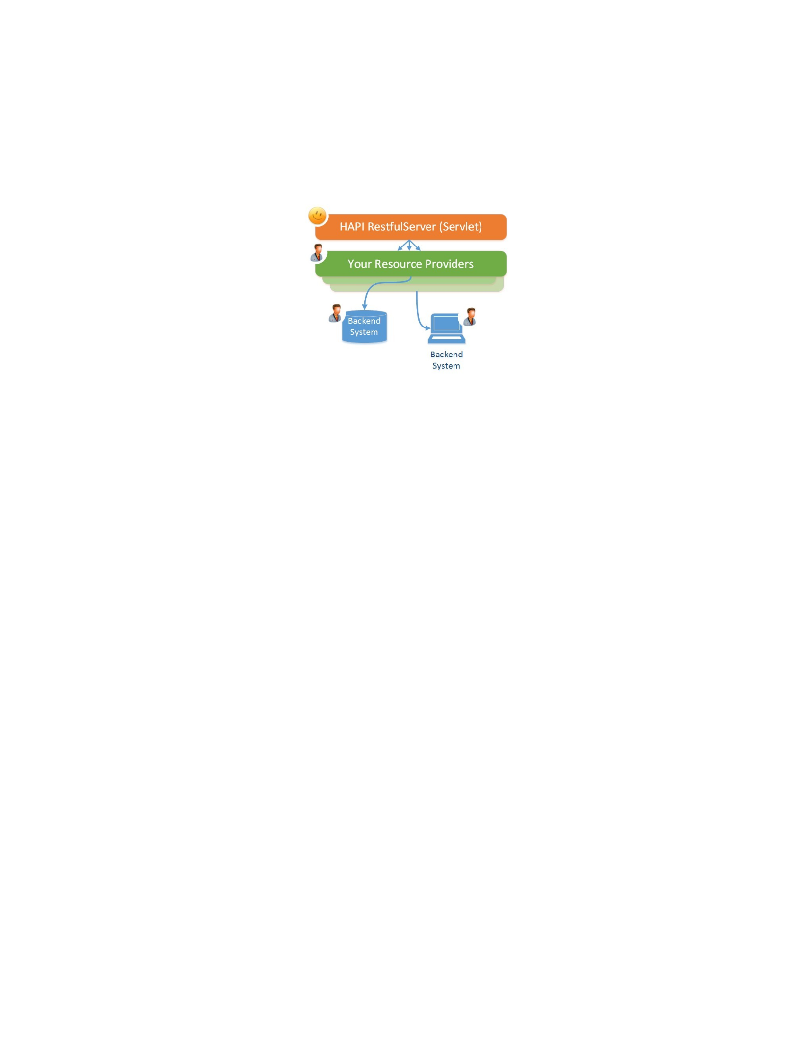
FHIR format/Back-end System format, and to interact with the Back-end System. The Back-end
System is a Health IT system (HIT) that handles the Resource Providers requests to retrieve or
modify the actual Electronic Health Records (EHR).
Figure 2.8. The HAPI-FHIR Server Architecture (HAPI community, 2016).
The HAPI-FHIR library also provides a general HAPI server interceptor (University Health
Network, 2016) which is programmatic approach that allows a developer to examine each
incoming HTTP request to add useful features to the HAPI ResfulServer such as authentication,
authorization, auditing, logging, etc. The general HAPI interceptor, the InterceptorAdapter class,
defines a number of methods that enable a developer to interact with the incoming HTTP
requests at different points of the request lifetime. As Figure 2.9 shows, these methods are:
incomingRequestPreProcessed that is invoked before performing any action to the request;
incomingRequestPostProcessed that is invoked after determining the request type which
classifying the request; incomingRequestPreHandled which is invoked before sending the request
to the Resource provider; and, outgoingResponse which is invoked after the request is handled by
the appropriate Resource provider. Each of these methods must returns either true, to continue
processing the request, or false, to abort and reject the request. Moreover, a developer may
extend the InterceptorAdapter class and implement the needed methods and register the extended
class in the HAPI ResfulServer.
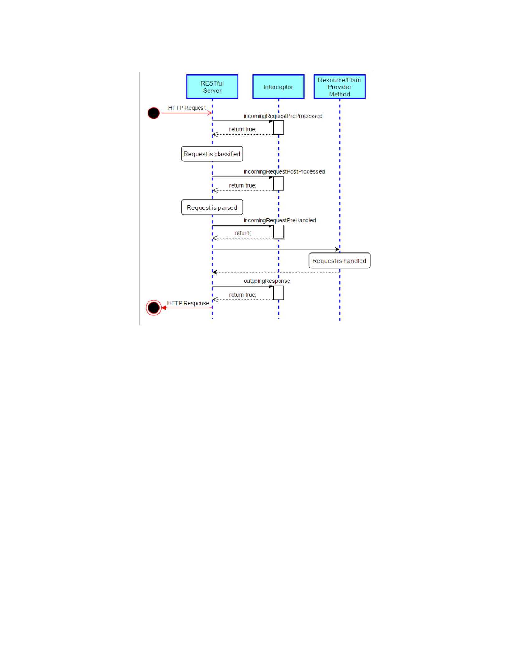
Figure 2.9. The Methods of HAPI Interceptor (University Health Network, 2016).
2.4 A Healthcare Scenario
To assist in explaining FSICC and all of its components and features in this dissertation, this
section presents a healthcare scenario that has two mHealth client apps, the Connecticut
Concussion Tracker (CT2) and ShareMyHealth, and two HIT systems, the open electronic health
record, OpenEMR (OpenEMR, 2016) and MyGoogle. To begin, CT2 is a mHealth app, as
shown in Figure 2.10 for Android and iOS devices, which is developed as a joint effort between
the Departments of Physiology and Neurobiology, and Computer Science & Engineering at the
University of Connecticut, in collaboration with faculty in the Schools of Nursing and Medicine.
The CT2 app allows the user (e.g., parent/guardian, coach, athletic trainer, school nurse) to report

and manage the concussion incidents of students from kindergarten through high school. The CT2
app uses an HIT system (i.e., OpenEMR) as a back-end system to maintain patients-related data.
The CT2 contains seven tabs starting from the top left and continuing to the second row in
Figure 2.10 (‘Login’, ‘List’, ‘Student’, ‘Cause’, ‘Symptoms’, ‘Follow-up’, and ‘Return’) where:
the ‘Login’ tab allows the user to enter a concussion, to retrieve an open case, or to find a student
by name; the ‘List’ tab which contains the list of students the user has permission to view and, for
each student gives him/her the option to add a concussion or edit an existing one; the ‘Student’
tab allows the user to input the student’s general information (e.g., name, birthdate, school, and
the date of concussion); the ‘Cause’ tab allows the user to specify how and where the concussion
occurred; the ‘Symptoms’ tab allows users to record the symptoms the student had within 48
hours and other pertinent data; the ‘Follow-up’ tab allows users to record the status of the student
over time; and, the ‘Return’ tab allows users to specify when the student can return to school
activities. Both versions (Android and iOS) of CT2 utilize an API (services) to manage CT2 data
as given in Table 2.1. Services CT1 and CT2 are used to: add/modify a student concussion status,
and, retrieve such status information, respectively. CT2 utilizes CT3 and CT4 services to: retrieve
all information about a student, and create/update new student information, respectively. Services
CT5 and CT6 provide ways for the CT2 to: create/update a student follow-up summary, and
retrieve follow-up information, respectively. Finally, by calling services CT7 and CT8, CT2 can:
retrieve all information about a student concussion, and add/modify new student concussion
information, respectively. CT2 defines four roles (see Table 2.2): Coach, Nurse, Trainer, and
Parent. All of the four roles can access: all GET services CT2, CT3, CT6, and CT7; and two PUT
services CT4, except Coach, and CT8. Moreover, Trainer has an additional PUT service (CT5)
while Nurse has access to all PUT services.
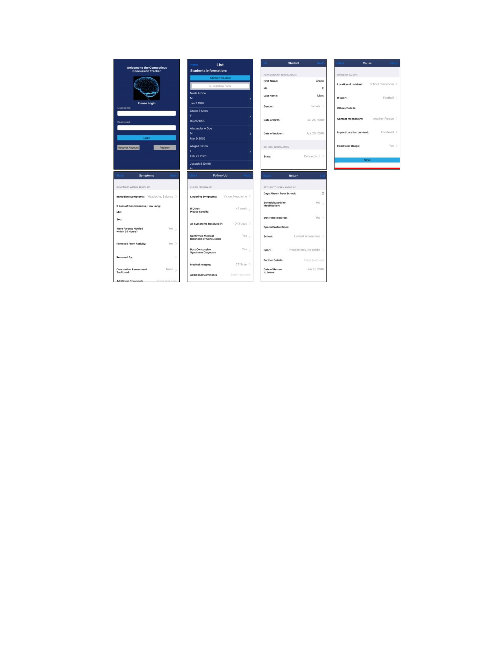
Figure 2.10. CT2 Mobile Application - iOS Version Interceptor.
ShareMyHealth is an mHealth app as shown in Figure 2.11 developed by a team of
undergraduate students at the University of Connecticut, for Android and iOS devices.
ShareMyHealth provides patients with a means to manage and share their fitness data across
multiple systems. Patients can gather data from multiple sources (e.g., MyGoogle, OpenEMR,
etc.) that can then be made available to medical providers. The first row of Figure 2.11 contains
four screens: Welcome for the initial opening of the app; Sign In with Google to authenticate the
user credentials to access his/her fitness data, such as Google Fit API (via MyGoogle system);
Initial Access for the user to define fitness data; and Home where the user sees their basic
information and can access their “Health” and “Settings” pages. The second row of Figure 2.11
contains four screens: Health View for viewing information on steps, calories, weight, and height;
and a Settings page to view setting such as name, gender, date of birth, etc.; and, a second setting
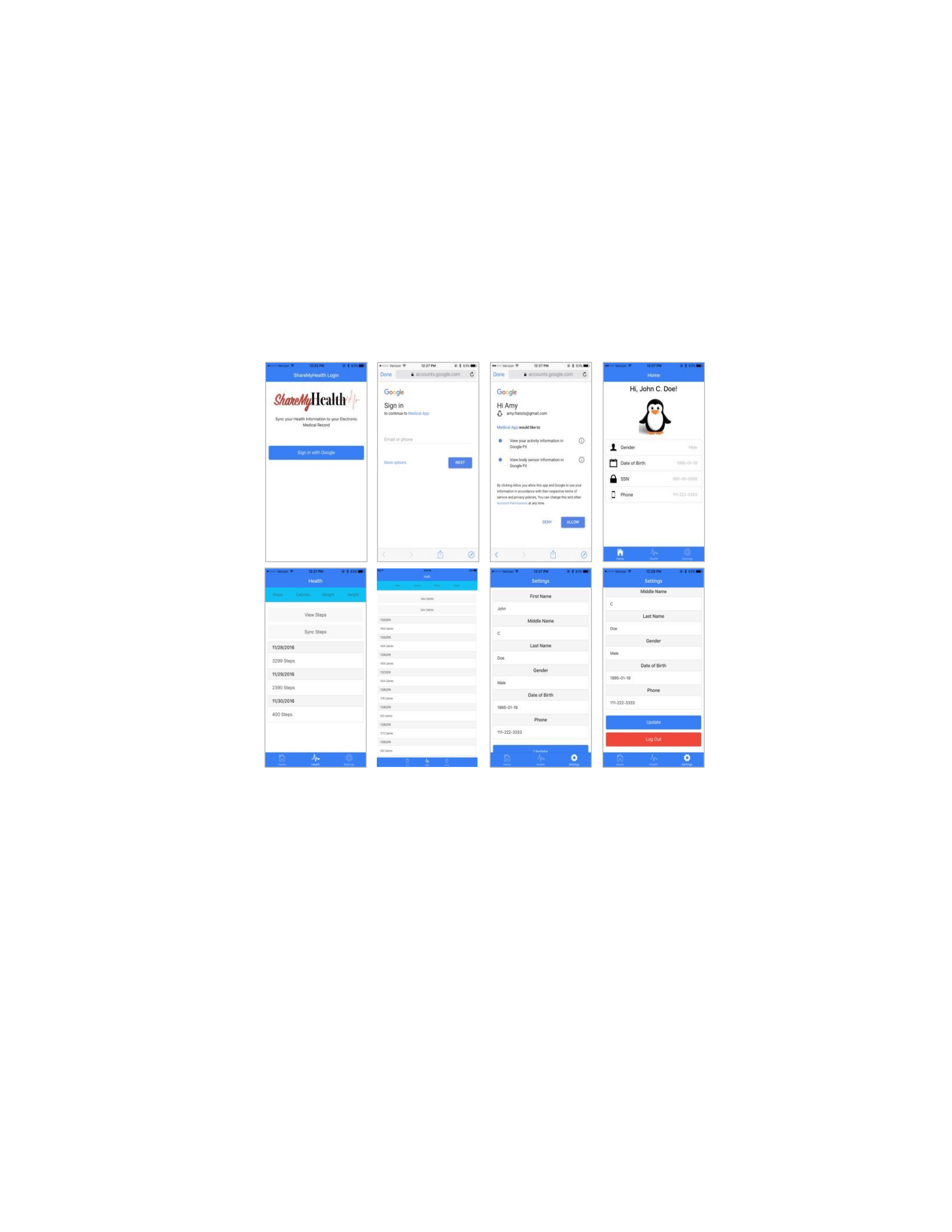
page that to modify information. Pressing the “View Steps” button utilizes the user’s Google API
Token to pull their data from the Google Fit cloud (via MyGoogle system). When a user presses
the “Sync Steps” button, the app packages the data into Google Fit via MyGoogle system which
in turns sends the information into OpenEMR via OpenEMR API. Settings such as name, gender,
etc., are updated by direct calls from ShareMyHealth to OpenEMR.
ShareMyHealth has access to a RESTful API (SMH1 to SMH5 services, see Table 2.3).
Moreover, the ShareMyHealth API makes calls (via MyGoogle system) to: Google OAuth API
that prompts the current user (patient) to allow ShareMyHealth access to the user’s Google Fit
data; Google REST Fit API to access measurement data (step, height, weight, and calorie); and
OpenEMR API to read and update patient data. Specifically, ShareMyHealth utilizes services
SMH1 and SMH2 to add/update and read a patient’s measurements data, respectively.
ShareMyHealth calls services SMH3 and SMH4 to add/update and read a patient’s demographic
information. In addition, service SMH5 is used to grant ShareMyHealth app (using its Token) an
access to the user (patient) fitness data. ShareMyHealth has two roles (see Table 2.4): Patient,
that has access to all five services, and Physician, that has access to all services but SMH1 and
SMH3.
Figure 2.11 . ShareMyHealth Mobile Application.

Table 2.1. CT2 Services.
Sid Service Name
CT1 PUT /CT2/concussion/status statusINFO
CT2 GET /CT2/concussion/status statusID
CT3 GET /CT2/student studentID
CT4 PUT /CT2/student/add studentINFO
CT5 PUT /CT2/followup/add followupINFO
CT6 GET /CT2/followups followupID
CT7 GET /CT2/concussion/student studentID
CT8 PUT /CT2/concussions/add concussionsINFO
Table 2.2. CT2 Roles.
Rid Role Service Name
CTR1 Coach CT2, CT3, CT6 – CT8
CTR2 Nurse CT1 – CT8
CTR3 Parent CT2 – CT4, CT6 – CT8
CTR4 Trainer CT2 – CT8
Table 2.3. ShareMyHealth Services.
Sid Service Name
SMH1 PUT /SMH/newMeasure/mID mINFO
SMH2 GET /SMH/Measures/mID
SMH3 PUT /SMH/newPatient/pID pINFO
SMH4 GET /SMH/Patients/pID
SMH5 PUT /SMH/Users/uID Token

Table 2.4. ShareMyHealth Roles.
Rid Role Service Name
SMHR1 Patient SMH1 – SMH5
SMHR2 Physician SMH2, SMH4, SMH5
OpenEMR (OpenEMR, 2016) is an open source Electronic Health Record (EHR) system and
a medical practice management app that can be utilized by any health/medical organization
around the world. OpenEMR is a Meaningful Use Stage 2 certified (Himss.org., 2016) and is
expected to be a Meaningful Use Stage 3 EHR certified soon (Himss.org., 2016). In addition to a
web-based interface, OpenEMR has a RESTful API from which we have selected a subset of
eight services as shown in Table 2.5. Services OEMR1 and OEMR2 enable an app (or a user via
an app) to add/update a note about a patient, and, retrieve information about such a note,
respectively. An app may utilize services OEMR3 and OEMR4 to: retrieve patient information,
and, create/update new patient information, respectively. Services OEMR5 and OEMR6 provide
ways for an app to: create/update a patient follow-up summary, and, retrieve information about
such a follow-up, respectively.
Finally, by calling services OEMR7 and OEMR8, an app can: retrieve patient condition
information, and, add/modify new patient condition information, respectively. Moreover, the
OpenEMR system defines eight roles (see Table 2.6): Patient, Physician, Coach, Nurse, Trainer,
Parent, CT2, and MyGoogle in which the last two roles are designed for CT2, and MyGoogle,
respectively. The roles Nurse, Trainer, and Parent can access: all GET services OEMR2, OEMR3,
OEMR6, and OEMR7; and two PUT services OEMR4 and OEMR8. Moreover, Trainer has an
additional PUT service (OEMR5) while Nurse and Physician roles have access to all PUT
services. In addition, the Physician can only access OEMR2 and OEMR4 services, while the

Patient role can access the services OEMR1, OEMR2, OEMR3 and OEMR4. The Coach role can
access all services except OEMR1, OEMR4, and OEMR5. Moreover, the MyGoogle role is
restricted to access OEMR1 and OEMR2 services, while the CT2 role can access all services.
Table 2.5. OpenEMR Services.
Sid Service Name
OEMR1 PUT /OpenEMR/updatepatientnotes noteINFO
OEMR2 GET /OpenEMR/getnotes noteID
OEMR3 GET /OpenEMR/getallpatients patientID
OEMR4 PUT /OpenEMR/addpatient patientINFO
OEMR5 PUT /OpenEMR/addvisit visitINFO
OEMR6 GET /OpenEMR/getvisits visitID
OEMR7 GET /OpenEMR/getlist conditionID
OEMR8 PUT /OpenEMR/addlist conditionINFO
Table 2.6. OpenEMR Roles.
Rid Role Service Name
OEMRR1 Physician OEMR2, OEMR4
OEMRR2 Patient OEMR1 – OEMR4
OEMRR3 Coach OEMR2, OEMR3, OEMR6 – OEMR8
OEMRR4 Nurse OEMR1 – OEMR8
OEMRR5 Parent OEMR2 – OEMR4, OEMR6 – OEMR8
OEMRR6 Trainer OEMR2 – OEMR8
OEMRR7 CT2 OEMR1 – OEMR8
OEMRR8 MyGoogle OEMR1, OEMR2
Table 2.7. MyGoogle Services.

Sid Service Name
MG1 PUT /MyGoogle/fitness/dataSources/dsID dsINFO
MG2 GET /MyGoogle/fitness/dataSources/dsID
MG3 PUT /MyGoogle/newPatient/pID pINFO
MG4 GET /MyGoogle/Patients/pID
MG5 PUT /MyGoogle/Users/uID Token
Table 2.8. MyGoogle Roles.
Rid Role Service Name
MGR1 SMH MG1 – MG5
Finally, MyGoogle is a HIT that we developed to act as a middle layer between the
ShareMyHealth app and the two HIT systems: OpenEMR and Google Fit (Google, 2017), which
is an open HIT system for sharing and managing patient fitness data (e.g., step, height, weight,
and calorie) that is maintained in the Google Fitness Store (in the cloud) that enables multiple
apps to access such data via Google Fit APIs. Google Fit consists of two APIs: Fit REST API to
add/update patient fitness data; and, Google OAuth API to authenticate apps to access users’
fitness data. MyGoogle HIT has an API (Table 2.7) to access OpenEMR API and Google Fit
APIs and acts on behalf of apps. The MyGoogle API consists of five services. MG1 and MG2
enable an app to add/modify and read users’ fitness data from/into Google Fitness Store via Fit
REST API, respectively. MG3 and MG4 add/update and read a patient’s demographic information
from/into OpenEMR via OpenEMR API, respectively. MG5 utilizes Google OAuth
API to authenticate an app (using its Token) to access a user’ fitness data. In addition, MyGoogle
defines one role, i.e., SMH, (see Table 2.8) which is designed to be assigned to ShareMyHealth
app. The SMH role can access all MyGoogle API services.


Chapter 3 Security Requirements and Cloud Computing Capabilities
for FSICC
As we discussed earlier in Section 1.2, the healthcare domain is an emergent application for
cloud computing, in which the Meaningful Use Stage 3 guidelines recommend health
information technology (HIT) systems to provide cloud services that enable health-related data
owners to access, modify, and exchange data. This requires that mobile and desktop applications
for patients and medical providers obtain healthcare data from multiple HITs, which may be
operating with different paradigms (e.g., cloud services, programming services, web services),
use different cloud service providers, and employ different security/access control techniques. To
address these issues, this chapter presents the four Security Requirements and the three Cloud
Computing Capabilities that underlie and support FSICC. These four security requirements and
three cloud computing capabilities for FSICC simplifies and enables client access via global
resources using standardized system APIs. A security requirement represents what we consider to
be the key security features for supporting security in FSICC. The four security requirements are:
Numerous and Varied Access Control Models, Control Access to Cloud Services Using RBAC,
Support Delegation of Cloud Services Using DAC, and Control Access to Cloud Services Using
MAC. A cloud computing capability represents what we consider to be the critical characteristics
for supporting cloud computing in FSICC. The three cloud computing capabilities of FSICC are:
Local Service Registration and Mapping to Global Services, Local Security Policies Registration
to Yield Global Security Policy, and Global Registration, Authentication, Authorization, and

Service Discovery for Consumers. To understand the role of security requirements and cloud
computing capabilities for FSICC, we reexamine Figures 1.1 to 1.3 which also provides a more
complete discussion of FSICC and its functionality.
To begin, recall that Figure 1.1 from Chapter 1 presented the architecture of FSICC. The
top of Figure 1.1, had client Applications (Web, Mobile, and Desktop) which corresponds to the
Clients box in the Involved Parties component that was at the top of Figure 1.2 from Chapter 1.
These client applications are interested in utilizing a subset of the available global services and
global security policies of FSICC. FSICC was shown in the middle of Figure 1.1 and had eight
boxes that interact with one another. The Clients Registry box, at the top of FSICC, is for clients
to register themselves into the FSICC. The next lower box is the Global Authentication box that
is responsible for verifying clients’ identities before allowing them to be authorized to access
global services of FSICC. The next box down is the RBAC/MAC/DAC interceptors box that is in
charge of allowing/denying clients requests to access global services of FSICC based on
roles/clearances. The Clients Registry, the Global Authentication, and the RBAC/MAC/DAC
interceptors boxes refer to the Global Policy Enforcement component that was shown in Figure
1.2. The Global Services box, in the middle of FSICC, is the set of global services that mirror
services of registered systems and are available to interested clients to utilize.
The next lower box is the Global Security Policy box which has the global security policy that
defines what set of global services each client can access based on RBAC, MAC, and DAC
models. The two next boxes are: the Security Policy Mapping box that is responsible for
combining a set of security policies from different systems and generating the global security
policy; and, the Services Mapping box which combines a set of services from systems into one
set of global services. The System Registry, at the bottom of FSICC, enables systems to provide

their services and security policies. The System Registry, the Services Mapping, the Global
Security Policy, and the Global Services boxes refer to the Generation of Global Policy and
Services component that was shown in Figure 1.2. The Security Policy Mapping box refers to
Security
Policy Mapping component that was shown in Figure 1.2. The bottom of Figure 1.1 had Web,
Programming, and Cloud Applications, which corresponds to the Systems box in the Involved
Parties component at the top of Figure 1.2, that are willing to provide their services and security
policies into the FSICC. Security requirements have influence on security policy and mapping
boxes as well as the RBAC, MAC, and DAC models and interceptors. Cloud computing
capabilities have influence on the services, service mapping, and system registry boxes.
In addition, FSICC that was given in Figure 1.2 is an infrastructure for cloud computing that
provides a global policy authorization and enforcement mechanism and is capable of supporting
different access control models such as RBAC, DAC, and MAC in the Access Control Models
component in the middle of the figure. This is the main component where security requirements
have an impact. FSICC organizes and globally manages the cloud services, APIs, and web
services from multiple service suppliers (systems) via the Systems box in the Involved Parties
component at the top of Figure 1.1 into a set of global services in the Global Services box in the
Generation of Global Policy and Services component in Figure 1.2. These are the main
components where cloud computing capabilities have an impact. This allows the mobile, web,
and desktop applications clients in the Clients box in the Involved Parties component at the top
of Figure 1.2 to be used to easily discover and utilize them in order to interact with multiple
constituent systems with a common interface. Representative technologies to support the
implementation of FSICC include: the HAPI FHIR reference model (Health Level 7, Fast

Health Interoperable Resources, 2016) from Section 2.3; the DIRECT project (The Direct
Project, 2016) that allows for the sharing of information with best practices that have trust and
privacy considerations; and, the HEART WG project (OpenID, 2016) that provides privacy and
security specifications for authorization and access to health-related RESTful APIs.
Furthermore, Figure 1.3 from Chapter 1 presented a high-level view of the FSICC’s main
aspects. Figure 1.3 has five horizontal boxes for each main aspect of FSICC and vertical boxes
that span across the horizontal boxes. The five horizontal boxes are: Architectural Blueprints box
that contain the different options for architectural option for connecting clients and systems with
FSICC; Unified Cloud Computing Access Control Model box with boxes for Schema Definitions,
Enterprise Definitions, Policy Definitions, FSICC Definitions, and Intercepting Definitions;
Access Control Models box for the ability to control services via RBAC, MAC, and DAC; GSP
(Global Security Policy) Generation and GAPI (Global API) Generation box for generating the
security policy from multiple systems to make global APIs available to clients; and, Global
Security Policy and Global API Utilization and Security Enforcement box that utilizes security
interceptors to allow/deny clients from access global services of FSICC. Moreover, the security
requirements for FSICC, which will be described in this chapter, are represented in Figure 1.3 by
the upper right vertical box SECURITY REQUIREMENTS that spans two horizontal boxes:
Unified Cloud Computing Access Control Model and Access Control Models. The three cloud
computing capabilities, which will be described in this chapter, are represented in Figure 1.3 by
the lower right vertical box CLOUD COMPUTING CAPABILITIES that spans two horizontal
boxes: Global Security Policy and Global API Generation, and Global Security Policy and
Global API Utilization and Security Enforcement.

The presentation in the remainder of this chapter is in four parts. Section 3.1 defines and
explains the four security requirements for FSICC: Numerous and Varied Access Control Models,
Control Access to Cloud Services Using RBAC, Support Delegation of Cloud Services Using DAC,
and Control Access to Cloud Services Using MAC. Section 3.2 details the three cloud computing
capabilities with associated components of the FSICC: Local Service Registration and Mapping to
Global Services; Local Security Policies Registration to Yield Global Security Policy; and, Global
Registration, Authentication, Authorization, and Service Discover for Consumers. Section 3.3
discusses related research in cloud computing as compared with FSICC. Note that the work in this
chapter has been published in (Baihan, M. & Demurjian, S., 2017).
3.1 FSICC Security Requirements
This section discusses four security requirements for FSICC, exploring the impact of the
SECURITY REQUIREMENTS vertical box in Figure 1.3. A security requirement represents
what we consider to be the key security features for supporting security in FSICC. To facilitate
this discussion, there must be a shift in focus on the concept of RBAC, DAC, and MAC
permissions on objects and operations to one that assigns permissions to individual cloud
services. For RBAC, this corresponds to the global services being assigned to different users by
role. For MAC, global services are assigned classifications (TS, S, C, U) with a user having a
clearance and performing domination checks on classification vs. clearance for every service
invocation. For DAC, this corresponds to the ability to delegate services from user to user by role
and potentially limited by classification/clearance checks if MAC has defined. The remainder of
this section presents and discusses the four security requirements: Numerous and Varied Access

Control Models, Control Access to Cloud Services Using RBAC, Support Delegation of Cloud
Services Using DAC, and Control Access to Cloud Services Using MAC.
Security Requirement 1 - Numerous and Varied Access Control Models. The first security
requirement acknowledges that the constituent systems (i.e., service suppliers) that wish to
publish access to cloud, API, or web services may have access control and security protocols that
are varied. Thus, FSICC must be capable of supporting a wide range of access control models
such as Role-based Access Control (RBAC) (Ferraiolo, Sandhu, Gavrila, Kuhn, &
Chandramouli, 2001), Mandatory Access Control (MAC) (Bell & La Padula, 1976),
Discretionary
Access Control (DAC) (Dittrich, Härtig, & Pfefferle, 1988), Attribute-based Access Control
(ABAC) (Yuan, E. & Tong, J. , 2005), Usage Access Control (UCON) (Sandhu, R. & Park, J. ,
2003), etc. This leads to Security Requirement 1 - Numerous and Varied Access Control Models
and is represented in the Access Control Models horizontal box in Figure 1.3.
From the healthcare scenario of Section 2.4, we know that each HIT (MyGoogle and
OpenEMR) supports RBAC as illustrated in Tables 2.6 and 2.8. These systems also support DAC
to allow permissions (services) to be delegated from a physician Charles (user) to the on-call
physician Lois (user) after hours and weekends. FSICC, as was shown in Figure 1.1, enables
these systems to register their security policies (as shown for MyGoogle and OpenEMR in Tables
2.6 and 2.8) into FSICC via the System Registry box in Figure 1.1. This is the Registration and
Services Mapping box of the Generation of Global Policy and Services component in Figure 1.2,
in which security policies are combined via the Security Policy Mapping box in Figure 1.1,
Security Policy Mapping component in Figure 1.2, to generate the global security policy via the
Global Security Policy box in Figure 1.1, Global Policy box of the Generation of Global Policy

and Services component in Figure 1.2. Specifically, the global security policy should define, for
each role, the global services assigned by role. This was accomplished as discussed by mapping
permissions to call systems’ services (cloud, web, and API) from Table 2.5 and 2.7 into
permissions to call global cloud services.
Security Requirement 2 - Control Access to Cloud Services Using RBAC. The second
security requirement involves the large number of services that are published in the cloud by
multiple systems which are to utilized by numerous consumers, meaning that the usage of such
services is expected to be high, which needs to be controlled so that only certain consumers at
different times can have access to specific services. Thus, when all of the system services are
collected into a set of global cloud services, the resulting set can be controlled based on roles, as
shown in the RBAC box of the Access Control Models horizontal box in Figure 1.3, in which
each role can be assigned on a consumer-by-consumer basis. This leads to Security Requirement
2-Control Access to Cloud Services Using RBAC where global services can be assigned by role,
see the Role-based Access Control box of the Access Control Models component in Figure 1.2.
To illustrate, the global security policy may define nine global roles: GPhysician (global
physician), GPatient (global patient), GCoach (global coach), GNurse (global nurse), GParent
(global parent), and GTrainer (global trainer) would be assigned to individuals that are utilizing
applications, while GCT2 (global CT2), GMyGoogle (global MyGoogle), and GSMH (global
SMH) represent the roles of the systems and applications that may need to utilize services. The
GPhysician role is used by a doctor to access his/her patients’ electric information and to provide
better healthcare services for his/her patients. The GPatient role is used by a patient to access
his/her digital information and to request different healthcare services. The GCoach role is used
by a coach to report a health incident (e.g., concussion) at an athletic event with very limited

information on the patient. The GNurse role is used by a nurse to manage a patient’s health
incident from its occurrence to its resolution. The GParent role is used by a parent to both report
a health incident on his/her child while attending the athletic event or to track the current status
of his/her children that have health incidents. The GTrainer role is used by a trainer to do a
limited preliminary assessment if a health incident occurs at a training event. Moreover, The
GCT2 application role is used by a CT2 application to gather information related to patients’
concussion incidents. The GMyGoogle system role is used by the MyGoogle system to gather
medical and fitness information of patients. Finally, The GSMH application role is used by the
ShareMyHealth application to retrieve/add fitness information of patients. In addition, there is
also a need to work on the ability to constrain the invocation of a service based on values.
Security Requirement 3 - Support Delegation of Cloud Services Using DAC. Users of
applications, which consume services, may need: to collaborate with other users to accomplish a
better job; and/or to have other users to perform some of their tasks on behalf of them in case of
emergency. This leads to Security Requirement 3 - Support Delegation of Cloud Services Using
DAC where FSICC supports the ability to delegate cloud services from one user to another, see
the Discretionary Access Control box of the Access Control Models component in Figure 1.2 and
the DAC box of the Access Control Models horizontal box in Figure 1.3. For example, consider a
user Charles with a GPhysician role is leaving the office for the day or the weekend and is
interested in delegating his/her authority to access the services for his patient to the on-call
physician Lois who will be covering night and weekend inquiries from patients. In this case,
Lois will then be utilizing a mobile application to access patient data that is available via
OpenEMR services (see Section 2.4). Charles could delegate all or some of his OpenEMR
services to Lois.

For example, Charles may delegate global services that involve patient data. If the delegation for
Charles to Lois is during the week (Monday to Thursday) it could go into effect at 5pm (close of
business) and be revoked at 9am (start of business). For weekend calls the delegation would go
from Friday at 5pm to Monday at 1am.
Security Requirement 4 - Control Access to Cloud Services Using MAC. Many services
may access very sensitive information such as patient data that needs to be more strongly
controlled than other parts of the patient data. For example, mental health data is limited to a
psychiatrist or psychologist and not available to a family medical provider. This leads to Security
Requirement 4 - Control Access to Cloud Services Using MAC as shown in the Mandatory access
control (MAC) box of the Access Control Models horizontal box in Figure 1.3. This supports the
definitions and usage of classifications (for services) and clearances (for users) which are
instrumental in controlling access to a service and the data passed by a service. Thus, to further
restrict access to cloud services, FSICC supports MAC in addition to RBAC and DAC, has
shown in the Mandatory Access Control box of the Access Control Models component in Figure
1.2. That is, all of the global services may be labeled with classification levels, and all users may
be labeled with clearance levels. Specifically, each of the global cloud services in FSICC can all
be labeled with a classification level (i.e., TS, S, C, or U).
3.2 FSICC Cloud Computing Capabilities
The set of security requirements in Section 3.1 leads to the definitions of a set of three FSICC
cloud computing capabilities, as shown in the CLOUD COMPUTING CAPABILITIES vertical
box in Figure 1.3, that bring together all of the concept and focus on the process and components
of FSICC. Cloud Computing Capability 1, Local Service Registration and Mapping to Global

Services, is for systems to register local services which are then mapped to a global set. Cloud
Computing Capability 2, Local Security Policies Registration to Yield Global Security Policy, is
for systems to register their local security policy which is utilized to generate a global security
policy. Cloud Computing Capability 3, Global Registration, Authentication, Authorization, and
Service Discover for Consumers, is to support the process of a consumer's (mobile, web, or
desktop app) registration to discover and be authenticated and then authorized to utilize services.
The remainder of this section discusses these three cloud computing capabilities using the
healthcare scenario of Section 2.4.
Cloud Computing Capability 1 - Local Service Registration and Mapping to Global Services.
This cloud computing capability of FSICC enables a service supplier (system) to register its
cloud, programming, and/or web services as indicated by the arrows at the bottom of Figure 1.1,
as shown in the Security Policies and Services Registration and Global Services Generation
boxes of the GSP Generation and GAPI Generation horizontal box in Figure 1.3. Referring to
column 2 in Tables 2.5 and 2.7, OpenEMR registers the cloud services OEMR1 to OEMR8 and
MyGoogle registers its services MG1 to MG5. For eexampl, OpenEMR registers OEMR1 with
name OpenEMR, URI (/OpenEMR/updatepatientnotes), PUT CRUD method, and input variable
noteINFO; MyGoogle registers MG1 with name MyGoogle, URI
(/MyGoogle/fitness/datasource/dsID), PUT CRUD method, and input variable dsINFO.
The end result of the registration is that all of the cloud services, API calls, and web services
of systems are transitioned to a set of equivalent global services. For each registered cloud, API,
or web service, a global cloud service is created with appropriate components that mirror the
signature of the system service named as a new global cloud service, which was represented in
Figure 1.1 by the Services Mapping and Global Services boxes that car spawns to the Generation

of Global Policy and Services component in Figure 1.2. For example, the service OEMR1 can be
mapped to a new global service in FSICC. Note that the existence of OEMR1 is no longer visible
to the mobile, cloud or web application; this is true for all of the converted services/API calls.
The end result is a unified set of global cloud services to be presented to the mobile, web, or
desktop applications as supported by the Services Mapping box of FSICC as was shown in
Figure 1.1, which maintains a mapping list of system to global cloud services.
Cloud Computing Capability 2 - Local Security Policies Registration to Yield Global
Security Policy. This cloud computing capability allows HIT systems to register their local
security policies (roles and permissions to APIs) that can then be combined to yield a global
security policy, as shown in the Security Policies and Services Registration and Global Security
Policy Generation boxes of the GSP Generation and GAPI Generation horizontal box in Figure
1.3. The local policy registration process of this cloud computing capability enables a service
supplier (system) to specify the security requirements or policy to access its services (cloud, web,
and API) as indicated by the arrows at the bottom of Figure 1.1. After the systems register the
local services, as given in Tables 2.5 and 2.7, they can then register the local security policies that
are available in their systems as given in Tables 2.6 and 2.8. This includes for a particular HIT
system: the defined roles, the permissions that are defined on each local service, the permissions
authorized to each role, the classifications for each service, and the allowable delegations.
As local security policies are registered over time, a security administrator or policy engineer
is responsible to design and evolve an appropriate global security policy that would encompass
all of the local security requirements (from all different access control models) and provides a
unified, global view for the applications. This is supported in FSICC as shown in Figure 1.1 by
the Security Policy Mapping and Global Security Policy boxes, which correspond to the Security

Policy Mapping component and the Generation of Global Policy and Services component,
respectively, in Figure 1.2. The security engineer defines a global security policy over global
cloud services based on defined local roles and associated permissions in the bottom of Figure
1.1 to define a set of global roles and their permissions. This is accomplished by: defining global
roles, assigning global permissions to global cloud services, authorizing global roles to global
permissions, and defining constraints over these assignments. In the healthcare scenario, the
global roles can be defined and evolved over time by considering and unifying all of the
particular roles of the originally registered HIT systems (such as MyGoogle and OpenEMR) and
new systems that are added over time.
Specifically, for the healthcare scenario from Section 2.4, the RBAC permissions as given by
the roles and API services in Tables 2.6 and 2.8 are mapped to a global set of roles and the global
API services, respectively. For example, for the patient role in Table 2.6, the permissions to the
OpenEMR services OEMR1-OEMR5 are mapped into the permissions to equivalent global cloud
services that are the authorized global services to the global patient role GPatient. Similarly, for
the SMH role in Table 2.8, the permissions to the MyGoogle services MG1-MG5 are mapped into
the permissions to equivalent global cloud services that are the authorized global services to the
global SMH role GSMH. Essentially, at a high-level, the authorized permissions of the Patient
role of OpenEMR and the SMH role of MyGoogle are mapped into new global roles GPatient
(global patient) and GSMH (global SMH), respectively. The security engineer needs to make
similar mapping and define new global roles (GPhysician, GCoach, GNurse, GParent, and
GTrainer) for the other local roles and the other systems that are also functioning as roles (GCT2
and GMyGoogle). These processes are supported by the Security Policy Mapping box of FSICC

as was hownn in Figure 1.1. A mapping list of local to global security policies is maintained by
the Global Security Policy box of FSICC.
Cloud Computing Capability 3 - Global Registration, Authentication, Authorization, and
Service Discover for Consumers. This cloud computing capability enables services consumers
(mobile, web, or desktop app) to register themselves, which then allows application users to
discover and be authenticated and then authorized to utilize services by role, as shown in the GSP
and GAPI Utilization and Security Enforcement horizontal box in Figure 1.3. The intent is to
provide access for application users to the global roles and the authorized global services. The
global registration activity of this cloud computing capability is supported by the Client Registry
box of FSICC as shown in Figure 1.1, which corresponds to the Registration and Services
Mapping box of the Generation of Global Policy and Services component in Figure 1.2. The
global authentication activity of this cloud computing capability is supported by the Global
Authentication box of FSICC as was shown in Figure 1.1, which corresponds to the Global
Authentication box of the Global Policy Enforcement component in Figure 1.2. The global
authorization activity of this cloud computing capability is supported by the RBAC/MAC/DAC
Interceptors box of FSICC as shown in Figure 1.1, which corresponds to the RBAC Interceptor,
MAC Interceptor, and DAC Interceptor boxes of the Global Policy Enforcement component in
Figure 1.2. The service discovery activity of this cloud computing capability is supported by the
Global Services box of FSICC as was shown in Figure 1.1, which corresponds to the Global
Services box of the Generation of Global Policy and Services component in Figure 1.2. Note that
we distinguish between consumers that are designing and deploying new mobile, web or desktop
applications vs. ones that are retrofitting an existing mobile, web, or desktop application that may
have its own access control (RBAC, DAC, and/or MAC) and cloud/web/programming APIs.

For consumers designing and deploying a new application, we can extend the healthcare
scenario of Section 2.4 with a mobile application for the patient and a desktop EHR application
for the physician, where all of these applications have been developed using the global cloud
services. To accomplish this development, each application must register with FSICC in order to
gain the relevant global roles to be authorized to each application user. A user of the mobile
application for the patient would be authorized to the GPatient global role and limited to the
services authorized to GPatient. The physician using the EHR desktop application would be
authorized to the GPhysician global role and limited to the services authorized to GPhysician.
For the HIT systems, MyGoogle would have the GMyGoogle global role with its authorized
global services. Note that OpenEMR services are not called by the consumers’ applications
instead MyGoogle services utilize OpenEMR services to store/retrieve patient demographic data
(see the healthcare scenario of Section 2.4).
Cloud Computing Capability 3 is also utilized to allow a consumer of a new application to
discover global cloud services for the healthcare scenario. This is accomplished by utilizing a
service discovery request to the Global Services box of FSICC as seen in Figure 1.1. The
discovery request returns a list of all available services by GSid, name, and description. Upon
successful discovery, the service consumer (application) can then submit a request to utilize one
or more discovered services. The application can send a list of the global services requested and
its identification information to the Global Authentication box of FSICC which authenticates the
application. Then, the RBAC/MAC/DAC Interceptors box of FSICC authorizes the appropriate
global user role associated with the requested services, and then forwards the service access
request along with the application’s global role to the Global Security Policy box of FSICC. The
Global Security Policy box then authorizes the requested global services only if the application’s

global role is authorized to access such a service. As a result of calling a global cloud service, the
mapped local service or API call of a local HIT system is invoked. Note that the HIT system
allows the call only as long as the application’s global role is mapped to an equivalent local role
that is authorized to access such a system service.
For example, suppose that the mobile application for the patient sends a service discovery
request to the Global Services box of FSICC to find a service to return the demographic
information for a patient. The discovery sends back the id of the required global service, name
(e.g., GET /FSICC/Patient/id), and a description such as calls the OEMR3 of the OpenEMR
system. Based on this, the patient mobile application can send a global service access request
along with the application identification information to the Global Authentication box. This box
can then authenticate the application and forward the request to the RBAC/MAC/DAC
Interceptors box that can authorize the application to utilize the GPatient role and forward the
global service access request along with the GPatient role to the Global Security Policy box. The
Global Security Policy box enables the patient mobile application to access the requested global
service, since the GPatient global role can access that global service. Then, the Global Security
Policy box retrieves the patient role, of OpenEMR system, which is mapped to the GPatient
global role. As a result of calling the authorized global service, an access request to the mapped
system service OEMR3 along with the patient local role is sent to the OpenEMR system. The
OpenEMR system allows the patient mobile application to access the service OEMR3 since the
patient local role is authorized to access OEMR3.
For consumers retrofitting an existing mobile, web, or desktop application, there is an extra
layer (i.e., the integration layer) of functionality that must be considered. Recall the CT2 and
ShareMyHealth mHealth (SMH) applications from the healthcare example in Section 2.4. Each

of these applications has its own API to access its database. Suppose that the developer of SMH
needs to expand SMH capabilities in order to store/retrieve patients’ fitness and demographic
information from MyGoogle and OpenEMR (via MyGoogle) systems, respectively. Suppose
also that the SMH has already defined roles for patient and physician that impact the way that the
app works for different users in terms of the fitness and demographic data collected can be
entered, viewed, and/or edited. In order to make use of the global roles and services of FSICC,
the existing SMH app needs to be able to map its own app roles to appropriate global roles, and,
programmatically link its API so that it will be able to call the appropriate global services of
MyGoogle. In order to support this programmatic link, the SMH app may also operate in the role
of a provider per cloud computing capability 1 to define and register a new set of services for the
SMH app that link its current API services to the global services. This requires a similar process
as described above to map from the local SMH roles to the global roles.
3.3 Related Work in Cloud Computing
In this section, we present a number of related efforts in cloud computing, from both academic
and industrial communities, that are solving similar problems to FSICC, comparing and
contrasting their work to FSICC. The first effort (Buyya, Ranjan, & Calheiros, 2010) proposed a
framework named InterCloud for federating cloud services to manage the services of multiple
cloud service providers in which the framework allocates cloud services to the cloud consumers
based on quality of service (QoS) needs of the consumer. To accomplish this, the Cloud Broker,
which is a component of their framework, determines the most suitable cloud service provider
based on the cloud services preferences through the Cloud Exchange, which is another
component of InterCloud. Our use of global services in FSICC provides a one-stop shopping

location for consumers which is similar to InterCloud since both frameworks remove the
consumers’ needs to search through many cloud providers. Further, our work utilizes the global
roles (and their assigned services by RBAC, DAC, and MAC) in order to control which services
each consumer is allowed to perform which is different from their work that does not provide any
security features to control access to the cloud services.
A second effort (Nair, Porwal, Dimitrakos, Ferrer, & Tordsson, 2010) introduced a framework
design for cloud services that supports features including: data confidentiality and integrity for
cloud service consumers; enable cloud service providers to publish cloud services that are unified
to the cloud service consumers; and, manage the published cloud services. Their framework
allows the cloud service providers to receive access requests from the framework without the
knowledge of the actual service consumer requesting such an access, and enforces access control
over the published cloud services. Their approach contrasts with our approach, particularly for
the healthcare domain, where the knowing of the identity of the consumer by the provider is vital
to restrict access to protected health information (PHI). Moreover, the main common features
between our framework and their framework are: unifying multiple services from different
providers to the consumers side, and controlling the unified services using access control means.
A third effort in (Tordsson, Montero, Moreno-Vozmediano, & Llor, 2012) proposed a cloud
broker that enables a heterogeneous set of cloud service providers, in which each provider may
require a different infrastructure to operate, to integrate with the cloud broker. Such a cloud
broker is capable of: optimizing placement of virtual infrastructures across variant clouds; and,
hiding the processes of deploying and managing the cloud services of the cloud providers. The
proposed broker utilizes a scheduling algorithm that manages the processes of cloud services
deployment. Our work on FSICC is similar to their effort, since our global roles and services

effectively hide the location of the local services providers which is similar to the cloud broker
approach in hiding the processes of deploying and managing the cloud services. Our work
utilizes
RBAC, DAC, and MAC access control models to control which services each consumer can
access which is different from their work that does not provide any security features to control
access to cloud services.
The fourth effort (Vordel, 2016), the Vordel Cloud Service Broker, supports integrating local
on-site applications with offsite cloud services via the Multi-Domain Registry, one main
component of Vordel. Vordel also provides monitoring, and management services. Vordel is
located between the cloud service providers and the cloud consumers referred to as organizations.
An organization may utilize Vordel broker to introduce a level of trust within the cloud
application of such an organization. The work on Vordel is similar to our efforts in FSICC since
they map the services of cloud providers to organizations’ applications via a Multi-Domain
Registry and we map local roles/services to global roles/services that offer RBAC, DAC, and
MAC security. The main difference between our and theirs is that they do not clearly
explain the way the integrated services in the Multi-Domain Registry are controlled in term of
what cloud services each consumer is restricted to access.
A fifth effort (Jamcracker, 2016), the JamCracker platform, unifies the processes of cloud
management and governance. Specifically, JamCracker provides a number of services including:
risk and policy compliance management; operation management; and, create, deliver, and
multicloud services management. JamCracker also allows cloud service providers to unify
delivery and management of private and public cloud application/services and distribute them to
cloud service consumers. JamCracker enables cloud service providers to publish their services

and virtualized applications along with security policies (only RBAC is supported) to control
their services and applications via the JamCracker Connect, one main component of the
JamCracker platform. The main similarities between our work on FSICCC and the JamCracker
are both frameworks that unify multiple services from different providers to the consumers side,
and control the unified services using access control means. However, while our framework
supports controlling access to the unified services using RBAC, MAC, and DAC, JamCracker
only supports RBAC as an access control mechanism.
A final effort (Amato, Di Martino, & Venticinque, 2012) proposed a cloud broker that acts as a
component that: manages the use, performance, and delivery of cloud services; and, mediates the
process of enabling cloud service consumers to access cloud services of service providers. This is
achieved by the proposed cloud broker utilizing an agent that dynamically identifies a set of
cloud services from various providers based on the service consumer requirements. The
architecture of the cloud broker agent is presented along with its implementation in (Amato &
Venticinque, Multi-objective decision support for bro-kering of cloud sla, 2013). Their effort is
similar to our work on FSICC since both works remove the consumers’ needs to search through
many cloud providers. However, their effort utilizes an agent-based approach to find one cloud
provider that most suit the needs of the cloud consumer, while FSICC unifies many services from
multiple cloud providers to be used by the cloud consumers. Moreover, while our framework
supports controlling access to the unified services using RBAC, MAC, and DAC, their effort
does not provide any security features to control access the cloud services.
The major difference between our work in FSICC and the aforementioned efforts is that their
focus is on solving portions of the problems that we are attempting to address in FSICC; none of

these efforts provides a comprehensive solution to the problem of securing and integrating cloud
and none-cloud services provided from different service provides.
Chapter 4 A Unified Cloud Computing Access Control Model
(UCCACM) for RBAC, MAC, and DAC
This chapter defines and explains a Unified Cloud Computing Access Control Model
(UCCACM) for RBAC, MAC, and DAC that is intended to upgrade these existing access control
models so that they are capable of defining permissions based on services. The model has been
motivated and influenced by the four main security requirements of FSICC as presented in
Section 3.1. The first requirement, Numerous and Varied Access Control Models acknowledges
that the systems providing services to FSICC may have access control and security protocols that
are varied (i.e., RBAC, MAC, DAC, ABAC, etc.), which would require UCCACM to have broad
access control abilities. The second requirement, Control Access to Cloud Services Using RBAC,
offers one possible way to the availability of services to users by assigning roles that authorize to
access a sub-set of the available cloud services on a role by role basis. The third requirement,
Support Delegation of Cloud Services Using DAC, offers the ability for users of cloud services to
enable other consumers to utilize all or a sub-set of the user’s authorized cloud services in which
DAC can be utilized to keep a list of delegated services, along with authorized delegated users, in
which each user can delegate all or a sub-set of his/her authorized cloud services to another
consumer anytime. Finally, the fourth requirement, Control Access to Cloud Services Using

MAC, provides the ability users that need access to sensitive information in certain secure cloud
services to utilize MAC to label cloud services with sensitivity levels called classifications (e.g.,
Top Secret (TS) < Secret (S) < Confidential (C) < Unclassified (U)) which can be made available
to users that are assigned clearances under appropriate with read and write properties as
described in Section 2.3 of Chapter 2. These last three security requirements for RBAC, MAC,
and DAC, are the foundational capabilities that need to underlie UCCACM.
In support of these requirements, this chapter presents a Unified Cloud Computing Access
Control Model (UCCACM) for the FSICC in which UCCACM provides a set of details
definitions to cover all aspect of the four requirements above along with examples for each
definition. UCCACM also provides a single view of global services to applications and allows
those global services to be authorized according to RBAC (FSICC’s security requirement 2),
MAC (FSICC’s security requirement 4), and DAC (FSICC’s security requirement 3) policies;
this supports expected contribution EC-B: an Integrated RBAC, MAC, and DAC Model for
Cloud Computing from Section 1.5. Moreover, UCCACM is an access control model that utilizes
three main access control models (RBAC, MAC, and DAC) to define and enforce security
policies for both: clients/systems, and global resources. That is, each client/system defines
RBAC, MAC, and/or DAC security policies against its objects. Moreover, the security policies
for the global resources of FSICC are defined and enforced against global cloud services of such
global resources. UCCACM has a critical placement as a layer in the HighLevel View of FSICC
Research Areas and Foci of Figure 1.3, that provides of capabilities and functionalities that are
necessary to support the Access Control Models in the next layer. These two adjacent layers are
influenced by the four security requirements.

The rest of this chapter provides formal definitions of UCCACM in eight sections. Section 4.1
presents a set of core definitions on schemas to support authorizing users to a set of schemas
based on roles and/or sensitivity levels. Section 4.2 provides core definitions on enterprise
application that include definitions for clients, systems, and types of clients and systems as part
of the enterprise application. Section 4.3 discusses core definitions on RBAC, MAC, and DAC
models that describe the way that such access control models can be modified to support the four
security requirements of FSICC. Section 4.4 describes advanced definitions on enterprise
applications in which the security aspects of RBAC, MAC, and DAC models are introduced into
clients and systems of any enterprise application. Section 4.5 has core definitions on global
resources and permissions by API in which definitions that describe what are global services and
the way that such global services are controlled via means of RBAC, MAC, and DAC are
provided. Section 4.6 presents advanced definitions on FSICC that describe the way that services
and security policies of different systems are mapped. Section 4.7 discusses core definitions on
security interceptors for RBAC, MAC, and DAC along with enforcement checks that each
security interceptor utilizes. Section 4.8 presents related work on access control for cloud
computing. Throughout the entire presentation of
UCCACM, detailed examples will be provided utilizing the healthcare scenario of section 2.4
Chapter 2. Note that the work in this chapter has been published in (Baihan, M., et al., 2017).
4.1 Core Definitions on Schemas
To begin, Definitions 1 to 4 are adopted from work on adding RBAC, MAC, and DAC to

XML schemas (De La Rosa Algarin A. , 2014) (De La Rosa Algarin, Ziminski, Demurjian, &
Rivera Sánchez, 2014) that allowed XML schemas to be customized based on role and
classifications to customize what each user is authorized to see from instances of the schema.
Defn. 1: An element eeID,eNAME is defined as two-tuple that represents a single piece
of a data abstraction that describes one aspect of a data structure, where eID is the element’s
unique identifier, and eNAME is an element name.
Defn. 2: A schema (SC) is a data abstraction that represents the structure of a particular kind
of information, and is defined as a three-tuple SCSCID,SCNAME,SCE where SCID is a
schema’s unique identifier, SCNAME is a schema name, and SCE is a set of elements (as
defined in Defn. 1) that represent the schema.
Defn. 3: Each schema, SC j , has a set of jn schema instances, SCI j sci1,sci2,...,scijn , where scii
sciID ,sciV in which sciV is an element-value set of a schema for all elements in each
schema.
Defn. 4: Let o={read, insert, update, delete}, be the set of operations that can be performed
against an element (e) of a schema.
Example 4.1: A schema for the Patient resource can be represented as SC1 1,Patient,PaientE
where
PaientE {1,id , 2,name,3,gender , 4,birthDate }. A schema instance of
SC1can be represented as sci1 1,sci1V where sci1V {id,7 ,name, Ali , gender,male,

birthDate,200587 }.
4.2 Core Definitions on Enterprise Application
After establishing definitions for schemas and schemas’ elements that describe the way that
data in FSICC is organized to be exchanged from system to system or from system to client via
FSICC, in this section, we provide core definitions on main actors of FCISS that provide,
consume, and/or maintain such data using the defined schemas and schemas’ elements. These
actors form a concept of an enterprise application that includes clients, systems, and types of
clients and systems as part of the enterprise application. The next set of definitions, Definitions 5
to 8, are associated with a large-scale enterprise application that is comprised of clients and
systems. Specifically, the definition for enterprise application explains the Involved Parties
component of Figure 1.2. Furthermore, the definitions for clients and systems describe that
contents and types of Clients and Systems boxes of the Involved Parties component of Figure
1.2.
Defn. 5: An Enterprise Application, EAEAID,EANAME,EACS,EASS,EASCS , has a unique identifier (EAID),
name (EANAME), sets of client applications (EACS) and systems (EASS), and a set of schemas
(EASCS). EA, via FSICC, allows multiple clients (mobile, web, desktop) to interact with
multiple systems via APIs (cloud, web, programmatic).
Example 4.2: An enterprise application for health information exchange (EAHIE) would allow
applications for patients, family members, medical providers, insurance companies, etc. (e.g.,
CT2 and ShareMyHealth from Section 2.4), to interact with OpenEMR and MyGoogle (from
Section 2.4) via cloud, web, or programmatic APIs. These HITs utilize FHIR Resources, the

integration layer in Figure 1.1 from Chapter 1, (Health Level 7, Fast Health Interoperable
Resources list, 2016) which include schema representations in both XML and JSON. The
schemas defined in EASCS are used by each HIT system.
The inclusion of schemas as part of an EA allows for the modeling of the information utilized
in a cloud computing application to be represented. Many cloud computing applications utilize
cloud computing services that send/receive XML or JSON objects, which in turn based on
underlying schemas; this is true with FHIR and the API reference implementation. Thus, an EA
with schemas provides an actual link from the type of information and the APIs. Given example
4.2, definitions for client and system can be provided.
Defn. 6: A client in an EA is a mobile, web, or desktop application, top of Figure 1.1 from
Chapter 1, that includes, as part of its functionality, cloud-based services, web services, or
a programming API of services, and is interested in utilizing a subset of EASCS via
available cloud computing services. A client can be characterized based on the degree that
it is a consumer and/or a provider in a cloud, web, or programming service-based setting.
There are two different types of clients:
i. A Pure Client is only a consumer of services.
ii. A Mixed Client is primarily a consumer of services and is also a provider of a
small number of services.
Defn. 7: A system, bottom of Figure 1.1 from Chapter 1, in an EA provides functionality for
use by clients via cloud-based services, web services, or a programming API, and is

interested in providing access to a subset of EASCS via its services or API. A system can be
characterized based on the degree that it is a consumer and/or a provider in a cloud, web,
or programming service-based setting. There are two different types of systems:
i. A Pure System is only a provider of services.
ii. A Mixed System is primarily a provider of services and is also a consumer of
a small number of services.
Example 4.3: Recall the healthcare scenario from Section 2.4 and let us assume that the CT2
client does not provide services. Based on this assumption we can categorize the ShareMyHealth
and CT2 client Apps; and OpenEMR and MyGoogle systems as follows:
- CT2 client App is a pure client, since it only utilizes services from OpenEMR system
- ShareMyHealth client App is a mixed client, since it utilizes services from MyGoogle
system and provides a number of services
- OpenEMR system is a pure system, since it only provides services
- MyGoogle system is a mixed system, since it provides services and utilizes services from
OpenEMR
4.3 Core Definitions on RBAC, MAC, and DAC for Roles/Users
After providing definitions on enterprise applications, clients, and systems, in this section, we
transition to describe the way that three main access control models RBAC, MAC, and DAC, see
RBAC, MAC, and DAC boxes of the Access Control Models component in Figure 1.2, can be
modified to enable the clients and systems in an enterprise application to utilize such access
control models to protect their services from unauthorized access. The next set of definitions,
Definitions 8 to 30, discuss the way that the FSICC security requirements in Section 3.1 from

Chapter 3 are supported in our work. Specifically, providing RBAC features for systems and
clients supports the security requirement 2 of FSICC: Control Access to Cloud Services Using
RBAC. Moreover, providing MAC features for systems and clients supports the security
requirement 4 of FSICC: Control Access to Cloud Services Using MAC. Finally, providing DAC
features for systems and clients supports the security requirement 3 of FSICC:
Support Delegation of Cloud Services Using DAC.
Defn. 8: A role, r, is defined as a two-tuple r rID ,rNAME where rID is a role unique
identifier and rNAME is a role name.
Defn. 9: Let RC / S {r1,r2,...,rj} be defined as the set of j roles for a given client/system
where rj RC / S and rj rID j ,rNAMEj .
Defn. 10: In support of mandatory access control (FSICC’s security requirement 4), we define
a linearly-ordered set of sensitivity levels (U-unclassified < C-confidential < Ssecret <
TS-top secret) with the ability to assign levels of clearances (CLR) to users/clients and
classifications (CLS) to schemas’ elements and services.
In support of mandatory access control, Definitions 1 and 2 are revised in order to define the
classification on each schema and each element of a schema.
Defn. 1: (V2) An element eeID,eNAME,eCLS is defined as three-tuple element that represents
a single piece of a data abstraction that describes one aspect of a data structure, where eID
is the element’s unique identifier, eNAME is an element name, and eCLS is the element
classification, as described in Defn. 10.

Defn. 2: (V2) A schema (SC) is a data abstraction that represents the structure of a particular
kind of information, and is defined as a four-tuple SCSCID,SCNAME,SCE,SCCLS where
SCID is a schema’s unique identifier, SCNAME is a schema name, SCE is a set of elements
(as defined in Defn. 1v2) that represent the schema, and SCCLS is the schema classification
that is equal to the least secure of all of its constituent elements.
Given the V2 revised Defns. 1 and 2, the corresponding permissions can be defined for RBAC
and MAC on roles and users with Definitions 11 to 19 to present: the concept of a permission,
the way that permissions are associated with roles, the way that a user is defined with a
clearance, the way that a user assigned a role, and the way that different roles are related.
Defn. 11: A permission, p, is defined as a three-tuple p pID , pSCID , pO where pID is a permission
unique identifier, pSCID is ID of the involved schema (Defn. 2v2), and pO is the operation
(Defn. 4).
Defn. 12: A role permission, rp, is defined as a three-tuple rprpID, pID,rID where pID ,rID are the
IDs of the involved permission (Defn. 11) and role (Defn. 8), respectively.
Defn. 13: Each role r has a role-permission set (RPS) RPSr {rp1,rp2,...,rpk}of role
permissions (Defn. 12).
Defn. 14: A user, u, is defined as three-tuple u uID,uNAME,uCLR , where uID is a user unique
identifier, uNAME is a user name, and uCLR is a user clearance (Defn. 10).
Defn. 15: Let UC / S {u1,u2,...,u j} be defined as the set of j users for a given

client/system, where u j UC / S andu j uID j ,uNAMEj ,uCLRj .
Defn. 16: Each user ui UC / S can be assigned a role rj RC / S for a user role assignment
(ura),urak ui ,rj , that signifies that a user is limited to playing that role and the authorized
permissions. Note that a user can be assigned multiple roles but only plays one role in any
session with a client/system.
Defn. 17: The user-role-assignment set (URASC/S) for a client/system,
URASC/S {ura1,ura2,...,urak }is the set of all k user role assignments (Defn. 16), that contains an
entry for relevant user/role combinations that are applicable for RBAC in support of any
client/system.
Defn. 18: Each role r has a role-role set (RRS) 𝑅𝑅𝑆𝑟𝑖 = {𝑟1, 𝑟1, . . , 𝑟𝑘} based on the isa
role hierarchy as described in Section 2.2.
Defn. 19: The role hierarchy (RHC/S) for a client/system,
𝑅𝐻𝐶/𝑆 = {𝑅𝑅𝑆𝑟1, 𝑅𝑅𝑆𝑟2, . . , 𝑅𝑅𝑆𝑟𝑘} is the set of all k role-role sets (Defn. 18).
In support of discretionary access control (FSICC’s security requirement 3) and based on the
DAC concepts that were introduced in Section 2.2, we provide definitions 20 to 30 that
distinguish between the user who performs the delegation act referred to as an original user and
the user who acquires additional permissions based on a delegation act referred to as a delegated
user. These definitions also present the way that an original user is supported with different
options to perform the delegation (i.e., delegate role, delegate role permission, and delegate
clearance).
Defn. 20: An original role,or , is a system or client role that is delegable.

Defn. 21: An original role permission,orp , is in the role-permission set (RPS) of a specific
original role or .
Defn. 22: An original clearance, oc, is a clearance (Defn. 10) in a system or client that is
delegable.
Defn. 23: An original user, ou, is a system or client user who assigned: an original role or , in
which ouis illegable to delegate or or orp to another original userou; and/or an original
clearance ocwith read/write properties, in which ouis illegable to delegate oc to another
original userou.
Defn. 24: A delegated clearance, dc, is a clearance (Defn. 10) that is delegated to a user.
Defn. 25: A delegated role, dr , is a role that is delegated to a user.
Defn. 26: A delegated role permission, drp, is a role permission that is delegated to a user.
Defn. 27: A delegated user,du, is a user to whom a delegated role dr , delegated role
permission drp , or delegated clearance dcwill be delegated.
Defn. 28: Delegation Authority (DA): A Security engineer determines which users in a system
or client can delegate their roles/role permissions/clearance to other users in that system
or client.
Defn. 29: Pass On Delegation Authority (PODA) is a Boolean value assigned to a user which
determines if he/she can delegate his/her roles/role permissions/clearance to another user
(poda=true) or not (poda=false).
Defn. 30: A Delegation Set (DS) for a system or client is a set of active role/role
permission/clearance delegations DSC / S ={d1 ,d2 , … , dn } in which each active delegation
di {ou du dr drp dc, , / / } has three parts: original user (ou), delegated user (du), and a
delegated role (dr), a delegated role permission (drp), or a delegated clearance (dc).

4.4 Advanced Definitions on Enterprise Applications
As previously discussed in Section 3.2, we presented three main cloud computing capabilities
for FSICC with the associated components. These cloud computing capabilities were: Local
Service Registration and Mapping to Global Services, see the Security Policies and
Services Registration and Global Services Generation boxes of the GSP Generation and GAPI
Generation horizontal box in Figure 1.3; Local Security Policies Registration to Yield Global
Security Policy, see the Security Policies and Services Registration and Global Security Policy
Generation boxes of the GSP Generation and GAPI Generation horizontal box in Figure 1.3; and,
Global Registration, Authentication, Authorization, and Service Discover for Consumers, see the
GSP and GAPI Utilization and Security Enforcement horizontal box in Figure 1.3. Based on this,
this section provides a set of definitions, Definitions 31 to 33, that support the three
aforementioned cloud computing capabilities of FSICC. Also, a number of definitions from
Sections 4.1, 4.2, and 4.3 are redefined as version 2. To start, the three new definitions are for
systems and clients with RBAC/MAC/DAC.
Defn. 31: A cloud, web, or programming service of a client or system, denoted , is
defined as ID ,NAME,SIG,Type with unique ID, name, signature, and type for each
service. A signature SIG is further defined in two different ways based on the technology
used to create a service as following:
i. Web/cloud: SIG METHOD_TYPE,URI ,INPUT _VARIABLE where

METHOD_TYPE {Create,Read ,Update,Delete,GET,POST,PUT,DELETE} is the type of CRUD
method, URI a unified resource identifier URI, and INPUT _VARIABLE is the input
variable.
ii. Program: SIG METHOD _ NAME,RETURN _TYPE,PARAMETERS where METHOD_ NAME in the call name, RETURN _TYPE
is the return type, and PARAMETERS are the parameter names/types.
A service type Type of a web/cloud-based service can be: (read) if METHOD_TYPE is
Read/GET; or (write) if METHOD_TYPE is Create/Update/Delete/POST/PUT/DELETE. A
service type Type of a program-based service can be: (read) indicating that values of all
service parameters PARAMETERS will not be modified after the service call, (write) indicating
that values of all service parameters PARAMETERS can be modified after the service call, or
(read/write) indicating that values of some service parameters PARAMETERS can be modified
after the service call while values of other parameters will not.
Defn. 32: A system, Si SIDi ,SNAMEi ,SAPIi ,SSCi S ,SRi S ,SRPSi S ,SRHi S ,SUi S ,SURASi S ,SDSi S , Si EASS is
identified by a unique identifier, name, and cloud, web, or programmatic API of a
system, respectively, where a given SAPIi is comprised of a set of ij API services
SAPIi {1i ,2i ,3i ,...,ij} with each j as given in Defn. 31 along with a schema subset
SSCi
S , sets of roles SRi
S , role permission sets SRPSi
S , role hierarchy SRHi
S , users SUi
S , userrole
assignment set SURASi
S , and system delegation set SDSi
S (Definitions 2v2, 9, 13, 19,
15, 17 and 30 respectively).

Example 4.4: MyGoogle and OpenEMR (from Section 2.4) are two systems in EASS where there
are RESTful cloud services for MyGoogle, and RESTful web services for OpenEMR. Figures
4.1 and 4.2 define MyGoogle and OpenEMR systems, respectively, with the signature σSIG as a
placeholder for readability.
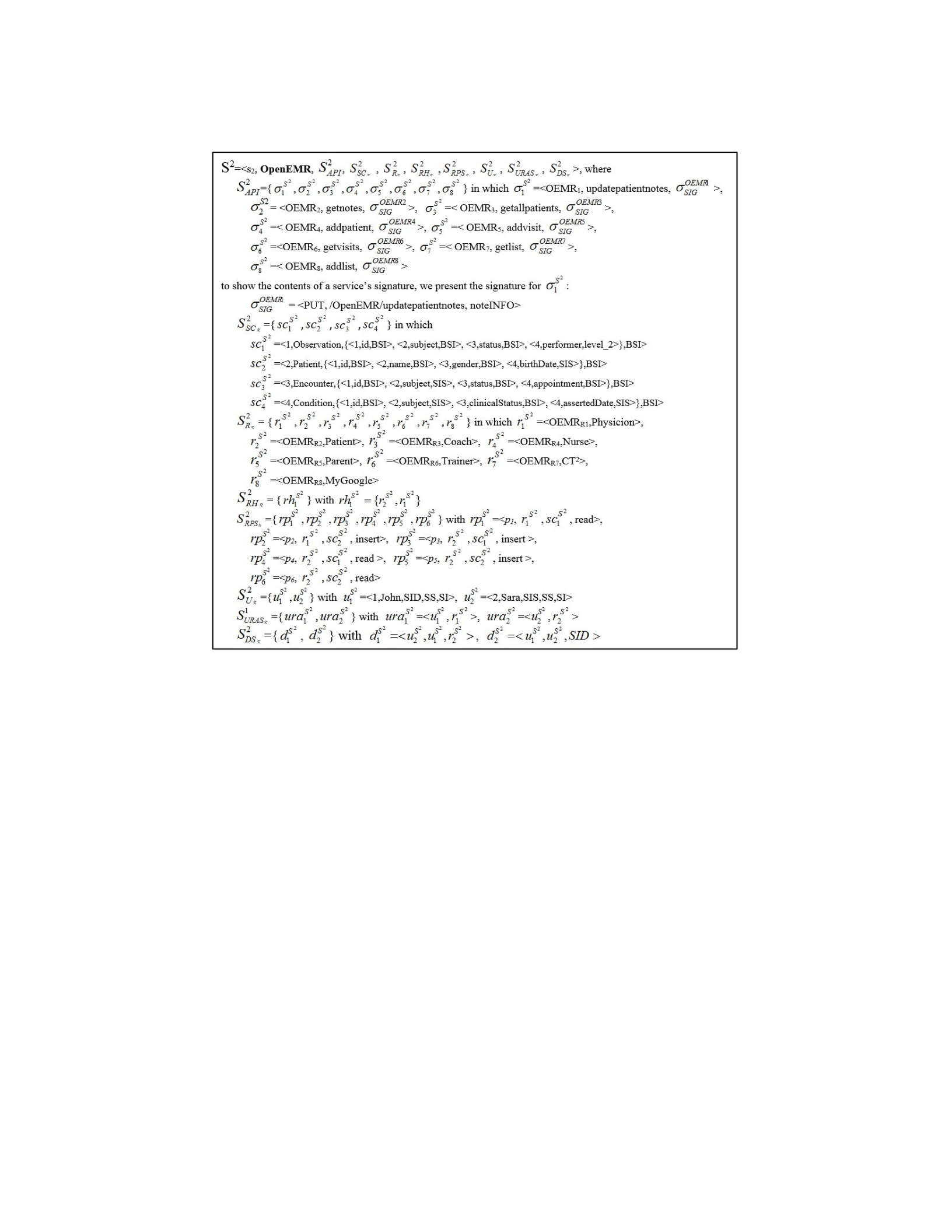

Figure 4.1. MyGoogle Notation for Example 4.4. Figure
4.2. OpenEMR Notation for Example 4.4.

Defn. 33: A client application, Ci EACS is defined as
Ci CIDi ,CNAMEi ,CAPIi ,CSCi C ,CRiC ,CRPSi C ,CRHi C ,CUi C ,CURASi C ,CDSi C with unique identifier,
name, CAPIi the set of ij API services CAPIi {1i ,2i ,3i ,...,ij}with each j as given in Defn.
31, and, a schema subset CSCi
C , sets of roles CRi
C , role permission sets CRPSi
C , role
hierarchy CRHi
C , users CUi
C , user-role assignment set CURASi
C , and client delegation set
CDSi
C (Definitions 2v2, 9, 13, 19, 15, 17 and 30 respectively).
Example 4.5: In Section 2.4 we have two clients: ShareMyHealth with RESTful cloud services;
and CT2 with RESTful web services, which are in EACS. Figures 4.3 and 4.4 define
ShareMyHealth and CT2 clients with the signature σSIG as a placeholder for readability.
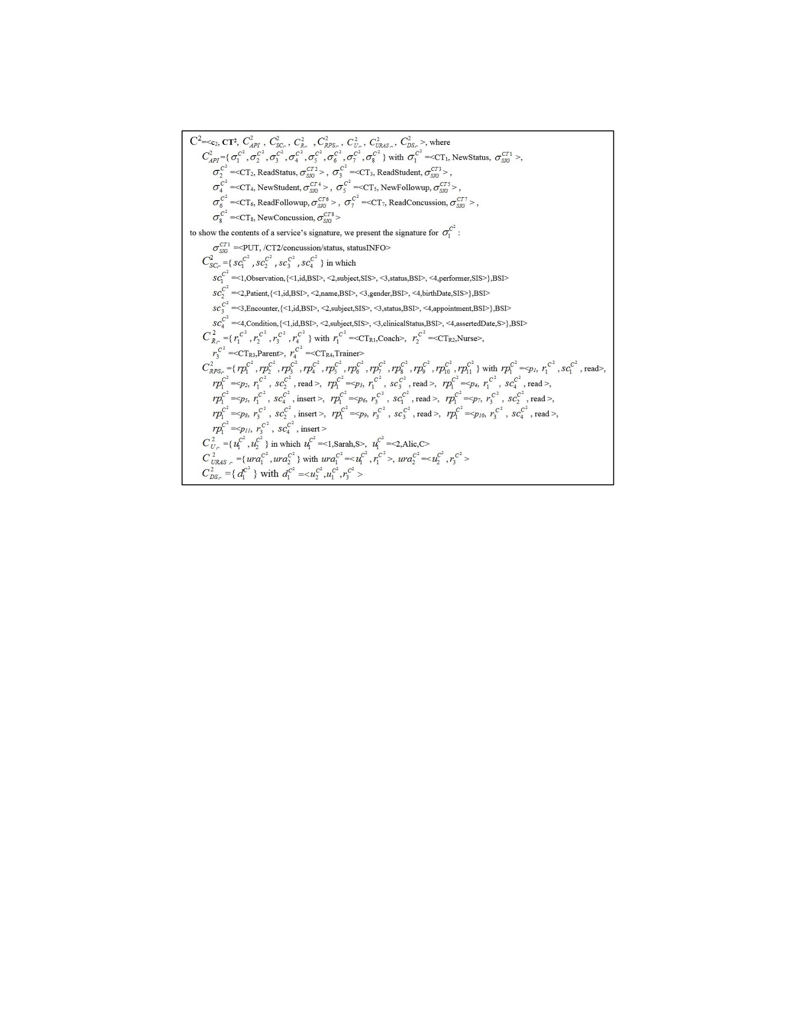
Figure 4.3. ShareMyHealth Notation for Example 4.5.
UCCACM for cloud computing, that supports the FSICC’s security requirements (see Section
3.1), also provides the means to represent a unified set of global services encapsulated into one
Global Resource for a given EA and its systems. This allows the clients to be able to utilize a set
of shared global services rather than specific services for each system that may be in different
formats (e.g., cloud services, web services, programmatic API services in different languages,
etc.). This is basically meant to support the FSICC’s cloud computing capabilities (see Section
3.2). Although, grouping multiple systems services attracts app developers, in a domain such as
healthcare, there is a need to create useful and rich apps (i.e., apps with many features) in an easy
and efficient way (i.e., avoid effort duplication). This need must be balanced against the potential
to create one great target that attackers can utilize to illegally access a large set of crucial and
Figure 4.4 . CT 2 Notation for Example 4.5 .

sensitive data (see Security Risks of adopting FSICC in Section 3.3), through services, such as
electronic health records of large number of patients.
Thus, an access control mechanism should be developed and utilized to restrict services access
only to the authorized users and their Apps.
Moreover, since there is a demonstrated need to protect such global services we make two
major observations: (1) there must be a shift in focus on the concept of RBAC permissions from
objects and operations (in the traditional RBAC model) to permissions that define individual
global services that are authorized by role to make invocations (calls) on objects; and (2) there is
a need to utilize a larger set of the four sensitivity levels of MAC such that the set of sensitivity
levels can adequately classify sensitive data in complex areas such as healthcare, note that the
healthcare-based security level approaches discussed in Section 2.2 are too focused on the
healthcare domain. In this dissertation, we present an access control mechanism, i.e., UCCACM,
that provides solutions for observations 1 and 2. Regarding the first major observation, Figure 4.5
shows the UCCACM for RBAC part that consists of four elements: Roles; Users; Sessions; and
Permissions (i.e., the defined service calls on objects), and five relations: User-Role (i.e., which
user assigned to which role); Role-Permission (i.e., which role authorized to which service in
which each service calls a specific object); UserSession (i.e., which user is active in the current
session); Role-Session (i.e., which role of the current user is active in the current session); and
Role-Role (i.e., which role, or set of roles, is the parent of the active role based on the isa role
hierarchy).
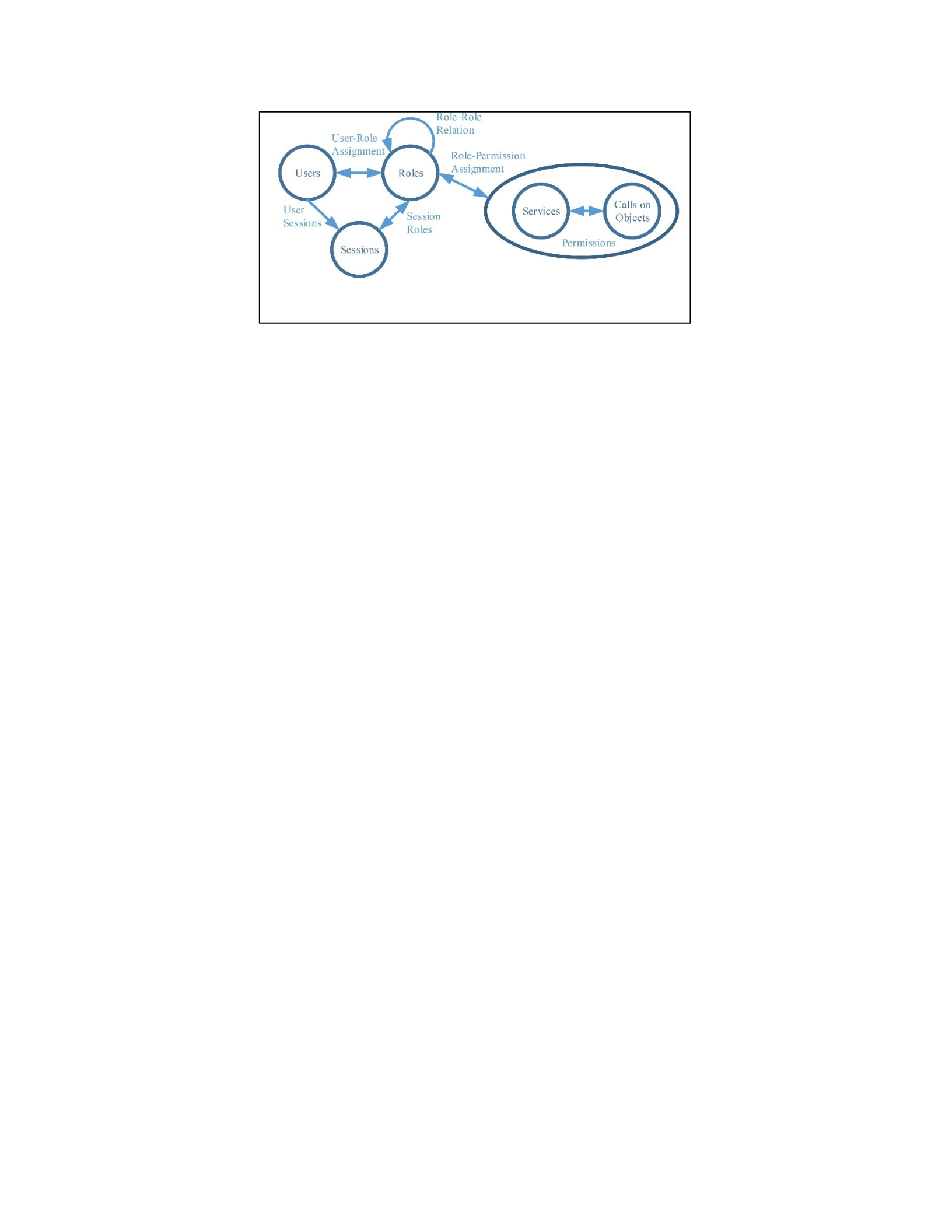
In the case of the second major observation, recall the work presented in Section 2.2 and
Figure 2.5. In Section 2.2, we reviewed the different HL7 confidentiality levels: U – unrestricted,
L – low, M – moderate, N – normal, R – restricted, and V – very restricted (Health Level 7.,
2014). In Section 2.2, we also reviewed the work on the lattice-based categories and
subcategories of sensitivities for healthcare that defined five main healthcare sensitivity levels:
0 – Basic Information, 1 – Medical History Data, 2 – Summary Clinical Data, 3 – Detailed
Clinical Data, 4 – Sensitive Clinical Data (Demurjian, Sanzi, Agresta, & Yasnoff, 2018) in Figure
2.5. Using that work as a basis, for the second major observation, we present a set of five
sensitivity levels (0-4) that can be utilized to classify data of any complex domain such as
healthcare, but not limited to the healthcare domain as follows:
Level 0: Public Information (PI) contains data that is freely available to anyone. Examples
for data at this level are: basic demographics such as city and state of residence; and
general personal information such as bachelor graduation year and university name.
Level 1: Basic Sensitive Information (BSI) contains data that has some restrictions. Examples
for data at this level are: detailed demographic data such as the patient name, full address,
and date of birth.
Figure 4.5 . The UCCACM for RBAC Part.

Level 2: Sensitive Information Summary (SIS) contains data that groups or summaries a set of
data that is classified as Basic Sensitive Information. Examples for data at this level are:
clinical data including prescription and over-the-counter medications; and key data of a
student’s academic record such as GPA.
Level 3: Sensitive Information Details (SID) contains data that elaborates and provides more
information about data that is classified as Basic Sensitive Information. Examples for
data at this level are: reports from imaging studies (CT Scans, MRIs, X-Rays); and
detailed academic information such as a report on a student academic record.
Level 4: Very Sensitive Information (VSI) contains very sensitive information about people or
organizations. Examples for data at this level are: sensitive information on a patient that
is used by medical specialists including data on genetics, substance abuse, mental health
psychotherapy notes; and sensitive employees’ information such as social security
number.
In the examples from this point forward, we refer to Level 0 to Level 4, respectively, by the
acronyms: PI, BIS, SIS, SID, and VSI.
Given Figure 4.5, we revise the Definitions 9, 15, 16, 17, and 30 to version 2 (v2) that
includes G (for global) as an option for a role set, user set, user role assignment, user-role
assignment set, and delegation set.
Defn. 9: (v2) Let RC / S /G {r1,r2,...,rj} be defined as the set of j roles for a given
client/system/Global Resource where rj RC / S /G and rj rID j ,rNAMEj .
Defn. 15: (v2) Let UC / S /G {u1,u2,...,uj} be defined as the set of j users for a given

client/system/Global Resource, where u j UC / S / G and uj uID j ,uNAMEj ,uCLRj .
Defn. 16: (v2) Each user ui UC / S /G can be assigned a role rj RC / S / G for a user role assignment
(ura), urak ui ,rj , that signifies that a user is limited to playing that role and the
authorized permissions. Note that a user can be assigned multiple roles but only play one
role in any session with a client/system/Global Resource.
Defn. 17: (v2) The user-role-assignment set (URASC/S/G) for a client/system/Global Resource,
URASC / S /G {ura1,ura2,...,urak}is the set of all k user role assignments (Defn. 16v2), that
contains an entry for relevant user/role combinations that are applicable for role-based
access control in support of any client/system/Global Resource.
Defn. 30: (v2) Delegation Set (DS) for a client/system/Global Resource is a set of active
role/role permission delegations DSC /S /G ={d1 ,d2 , … , dn } in which each active delegation
di {ou du dr, , / drp / dc } has three parts: original user (ou), delegated user (du), and a
delegated role (dr), a delegated role permission (drp), or a delegated clearance (dc).
To complete the changes, based on the presented sensitivity levels above we revise the Defn.
10 to version 2 (v2) to include the five sensitivity levels.
Defn. 10: (v2) In support of mandatory access control (FSICC’s security requirement 4), we
define a linearly-ordered set of sensitivity levels (0-PI < 1-BSI < 2-SIS < 3-SID <
4VID) with the ability to assign levels of clearances (CLR) to users/clients and
classifications (CLS) to schemas’ elements and services.

4.5 Core Definitions on Global Resources and Permissions by API
As we introduced RBAC, MAC, and DAC into definitions for systems and clients in
Section 4.3 and revised in Section 4.4, in this section, we present a set of definitions
(Definitions 34 to 39) that focus on the higher-level needs of UCCACM within FSICC.
Specifically, UCCACM provides a unified set of global services encapsulated into a number of
Global Resources. This supports FSICC’s cloud computing capability 1 in Section 3.2, see the
Security Policies and Services Registration and Global Services Generation boxes of the GSP
Generation and GAPI Generation horizontal box in Figure 1.3. This set of global services
belongs to a given enterprise application and its systems in which interested clients are able to
utilize authorized services from this set of shared global services. This is to remove the need for
clients to utilize multiple and possibly heterogeneous services from each system, separately, that
may be in different formats (e.g., cloud services, web services, programmatic API services in
different languages, etc.). Moreover, the FSICC’s global services are controlled using RBAC,
MAC, and/or DAC which supports FSICC’s cloud computing capability 2 in Section 3.2 as was
shown in the GSP Generation and GAPI Generation horizontal box in Figure 1.3.
Defn. 34: A global service of a global resource, denoted , is defined as
ID ,NAME ,SIG,CLS with unique ID, name, signature (similar to SIG in Defn.
31), and a classification (Defn. 10) for each service.
Defn. 35: A global resource, Gi represents a set of global services that are intended to map to
services from different Clients/Systems.
Defn. 36: For a global resource, Gi , a global service permission, gpi rIDi
k ,IDi
j , binds

a jth global service ij of GAPIi by identifier, IDi
j , to a role rki GRi
G by identifier, rIDi
j .
Defn. 37: For a global resource, Gi , and a role rki GRi
G , a role permissions set, RPS
rki =
{gpi
1 ,gpi
2 ,...,gpi
n }contains all of the n global service permissions gpi
j associated with a
role.
Defn. 38: For a global resource, Gi , the resource role permissions set, GRRPSi
G ={ RPS
r1i ,
RPS
r2i , …, RPS
rmi } contains all of the role permission sets for the m roles in GRi
G .
Defn. 39: A global resource, Gi can be represented as
Gi GIDi ,GNAMEi ,GAPIi ,GRi G ,GUi G ,GURASi G ,GRRPSi G ,GDSi G , is identified by a unique
identifier, name, and cloud API, respectively, where a given GAPIi is comprised of a set of
ij API
services GAPIi {i1,i2 ,i3,...,i j } with each j as given in Defn. 34 along with sets of roles GRi
G ,
users GUi
G , user-role assignment sets GURASi
G (Definitions 9v2, 15v2, and 17v2
respectively), a resource role permission set, GRRPSi
G (Defn. 38), and a resource delegation
set GDSi
G (Defn. 30v2).
Example 4.6: Figure 4.6 defines the Global Resource G1 with the signature σSIG as a placeholder
for readability. The global services (see Table 4.1) are organized into one Global Resource G1
with global roles (Table 4.2).
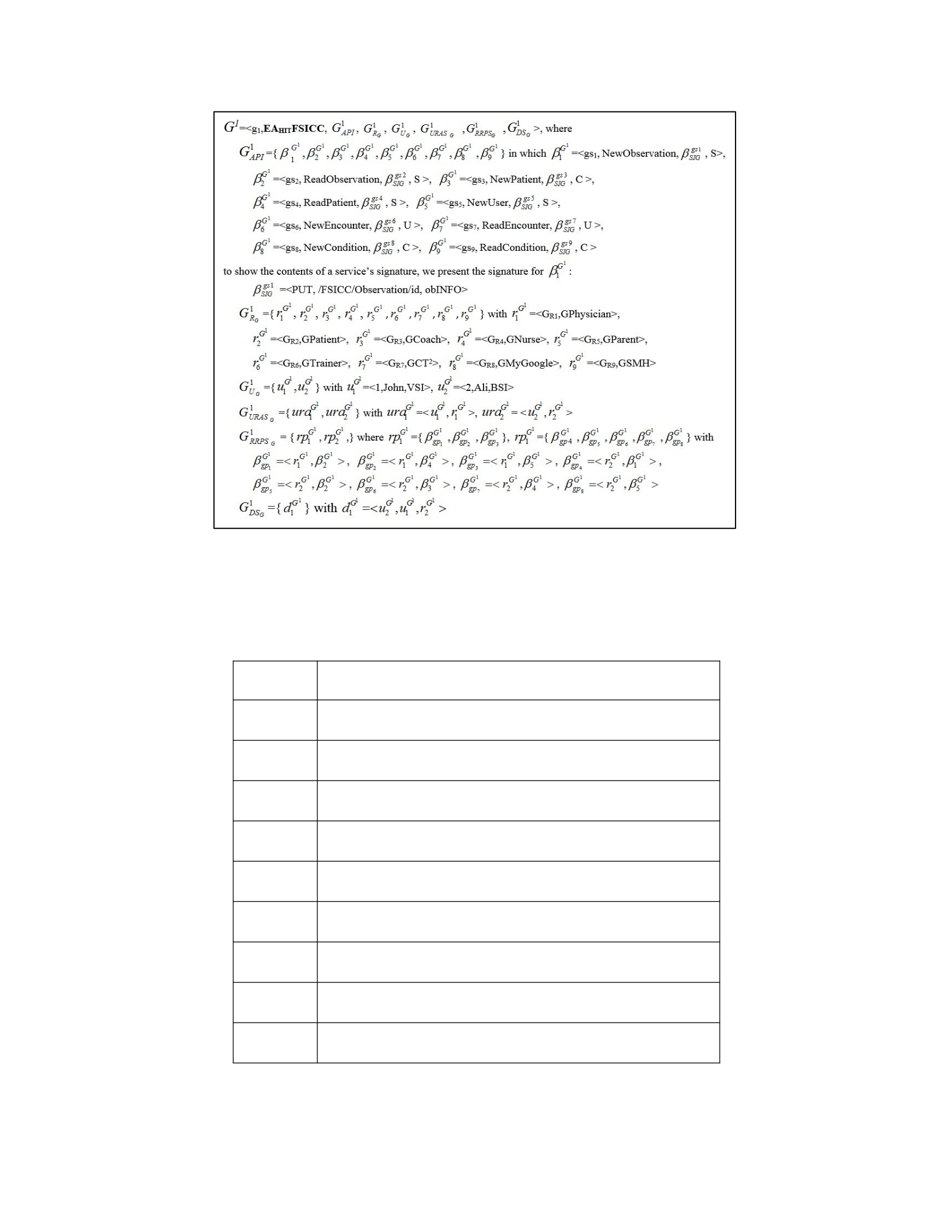
Figure 4.6. Global Resource G1 Notation for Example 4.6.
Table 4.1. FSICC Global Services for Global Resource G1
Gid Service Name
gs1 PUT /FSICC/Observation/id obINFO
gs2 GET /FSICC/Observation/id
gs3 PUT /FSICC/Patient/id ptINFO
gs4 GET /FSICC/Patient/id
gs5 PUT /FSICC/User/id usINFO, Token
gs6 PUT /FSICC/Encounter/id enINFO
gs7 GET /FSICC/Encounter/id
gs8 PUT /FSICC/Condition/id cnINFO
gs9 GET /FSICC/Condition/id

Table 4.2. FSICC Global Roles for Global Resource G1
Rid Role FSICC Services
GR1 GPhysician gs2, gs4, gs5
GR2 GPatient gs1 – gs5
GR3 GCoach gs2, gs3, gs7 – gs9
GR4 GNurse gs1 – gs4, gs6 – gs9
GR5 GParent gs2 – gs4, gs7 – gs9
GR6 GTrainer gs2 – gs4, gs6 – gs9
GR7 GCT2 gs1 – gs4, gs6 – gs9
GR8 GMyGoogle gs1, gs2
GR9 GSMH gs1 – gs5
4.6 Advanced Definitions on FSICC
After presenting a set of definitions that describes the unified set of global services of FCISS,
this section continues and provides a set of Definitions 40 to 48 that explains the way that
services and security policies of different systems are mapped to generate global services and
global security policy for FSICC. Specifically, this section defines the main components of the
FSICC and the way that such components are generated from the separate mapping involving
clients and systems. The first mapping is from clients (which have services to register) and
Systems to Global resources. The second mapping is from Client/System roles to Global roles
which is FSICC’s cloud computing capability 2 in Section 3.2 and the Security Policies and
Services Registration and Global Security Policy Generation boxes of the GSP Generation and
GAPI Generation horizontal box in Figure 1.3. The third mapping is from Clients/Systems API

services to Global API services which is FSICC’s cloud computing capability 1 in Section 3.2
and the Security Policies and Services Registration and Global Services Generation boxes of the
GSP Generation and GAPI Generation horizontal box in Figure 1.3.
Defn. 40: The Framework for Secure and Interoperable Cloud Computing (FSICC) can be
represented as FSICC= <G, R, U, URAS, RRPS> where G = {Gi | all i
resources} is a set of all of the global resources in which each Gi as given in Defn. 39, R
= {GRi
G alli} of all role sets from all i global resources, U = {GUi
G alli}of all user sets from
all i global resources, URAS ={GURASialli} of all user role assignment sets
from i the
global resources, and RRPS ={GRRPSi
G alli}of all resource role permission sets from all i
global resources.
Defn. 41: Client/System to Global Mapping CSGMFSICCi CID / S ID ,GID where each
Ci / S i is mapped to one Gi G.
Defn. 42: Client/System to Global Mapping Set:
CSGMSFSICC CSGMFSICC1 ,CSGMFSICC2 ,...,CSGMFSICCj , where CSGMFSICCj is as defined
in Defn. 41.
Defn. 43: Client/System API to Global API Mapping CSAGAMFSICCi CAPIID / SAPIID ,GAPIID
where each CAPIi/SAPIi is mapped to GAPIi.
G

Defn. 44: Client/System API to Global API Mapping Set
CSAGAMSFSICC CSAGAMFSICC1 ,CSAGAMFSICC2 ,...,CSAGAMFSICCj
, where CSAGAMFSICCj
is as
defined in Defn. 43.
Defn. 45: Client/System Roles to Global Roles Mapping CSRGRMFSICCi CRIDC /SRIDS ,GRIDG
where CRi
C /SRi
S are mapped to GRi
G .
Defn. 46: Client/System Roles to Global Roles Mapping Set
CSRGRMSFSICC CSRGRMFSICC1 ,CSRGRMFSICC2 ,...,CSRGRMFSICCj
, where CSRGRMFSICCj
is as defined
in Defn. 45.
Defn. 47: Client/System Users to Global Users Mapping CSUGUMFSICCi CUIDC /SUIDS ,GUIDG
where CUi
C /SUi
S are mapped to GUi
G .
Defn. 48: Client/System Users to Global Users Mapping Set
CSUGUMSFSICC CSUGUMFSICC1 ,CSUGUMFSICC2 ,...,CSUGUMFSICCj
, where CSUGUMFSICCj
is as
defined in Defn. 47.
Note that the mappings in Definitions 41-48 are performed by a FSICC security engineer in
regards to reconciling roles and APIs as part of the mapping process. Part of this process is
performed utilizing a set of algorithms for global RBAC policy generation, global MAC policy

generation and global DAC policy generation; this will be explored in detail in Section 6.3 of
Chapter 6.
Example 4.7: Table 4.3 contains the mappings of services and roles of MyGoogle, OpenEMR,
CT2, and ShareMyHealth (see Section 2.4). This is basically, the result of utilizing FSICC’s cloud
computing capability 1: local service registration and mapping to global services; and cloud
computing capability 2: local security policies registration to yield global security policy (see
Section 3.2). Table 4.3a is for the role mapping where the client role and system role could map
to the same global role, as shown for the first six rows, e.g., SMHR1 and OEMRR2 rows are the
Patient role for Client/System, respectively, that maps to the global Patient role GR2. Tables 4.3b
to 4.3e map CT2, ShareMyHealth, MyGoogle, and OpenEMR services, respectively, to global
services.
Table 4.3. Mapping Tables to Global Services.
a. Mapping Client/System to Global Roles.
Client
Rid
Client
Role Name
System Rid System Role Name Global Rid Global Role
Name
CTR1 Coach OEMRR3 Coach GR3 GCoach
CTR2 Nurse OEMRR4 Nurse GR4 GNurse
CTR3 Parent OEMRR5 Parent GR5 GParent
CTR4 Trainer OEMRR6 Trainer GR6 GTrainer
SMHR1 Patient OEMRR2 Patient GR2 GPatient
SMHR2 Physician OEMRR1 Physician GR1 GPhysician
OEMRR7 CT2 GR7 GCT2
OEMRR8 MyGoogle GR8 GMyGoogle

MGR1 SMH GR9 GSMH
b. Mapping of CT2 Services to Global Services.
Sid Service Name Gid FHIR
CRUD/Resource
CT1 PUT /CT2/concussion/status statusINFO G1 PUT Observation
CT2 GET /CT2/concussion/status statusID G2 GET Observation
CT3 GET /CT2/student studentID G4 GET Patient
CT4 PUT /CT2/student/add studentINFO G3 PUT Patient
CT5 PUT /CT2/followup/add followupINFO G7 PUT Encounter
CT6 GET /CT2/followups followupID G8 GET Encounter
CT7 GET /CT2/concussion/student studentID G10 GET Condition
CT8 PUT /CT2/concussions/add concussionsINFO G9 PUT Condition
c. Mapping of ShareMyHealth Services to Global Services.
Sid Service Name Gid FHIR
CRUD/Resource
SMH1 PUT /SMH/newMeasure/mID mINFO G1 PUT Observation
SMH2 GET /SMH/Measures/mID G2 GET Observation
SMH3 PUT /SMH/newPatient/pID pINFO G4 GET Patient
SMH4 GET /SMH/Patients/pID G3 PUT Patient
SMH5 PUT /SMH/Users/uID Token G5 PUT User
d. Mapping of MyGoogle Services to Global Services.
Sid Service Name Gid FHIR
CRUD/Resource
MG1 PUT /MyGoogle/fitness/dataSources/dsID dsINFO G1 PUT Observation
MG2 GET /MyGoogle/fitness/dataSources/dsID G2 GET Observation

MG3 PUT /MyGoogle/newPatient/pID pINFO G4 GET Patient
MG4 GET /MyGoogle/Patients/pID G3 PUT Patient
MG5 PUT /MyGoogle/Users/uID Token G5 PUT User
e. Mapping of OpenEMR Services to Global Services.
Sid Service Name Gid FHIR
CRUD/Resource
OEMR1 PUT /OpenEMR/updatepatientnotes noteINFO G1 PUT Observation
OEMR2 GET /OpenEMR/getnotes noteID G2 GET Observation
OEMR3 GET /OpenEMR/getallpatients patientID G4 GET Patient
OEMR4 PUT /OpenEMR/addpatient patientINFO G3 PUT Patient
OEMR5 PUT /OpenEMR/addvisit visitINFO G7 PUT Encounter
OEMR6 GET /OpenEMR/getvisits visitID G8 GET Encounter
OEMR7 GET /OpenEMR/getlist conditionID G10 GET Condition
OEMR8 PUT /OpenEMR/addlist conditionINFO G9 PUT Condition
4.7 Core Definitions on Interceptors
As we described earlier in Section 3.2 of Chapter 3, the global security policy of FSICC is
generated by the cloud computing capability 2 of FSICC, i.e., local security policies registration
to yield global security policy, that utilizes two components of FSICC: Security Policy Mapping
box of FSICC in Figure 1.1 and Global Security Policy box of FSICC in Figure 1.1. To enforce
the FSICC’s global policy defined on global resources with the allowed API service calls
controlled by RBAC (FSICC’s security requirement 2), MAC (FSICC’s security requirement 4),
and DAC (FSICC’s security requirement 3) permissions, this section introduces a set of
definitions for security Interceptor that is able to intercept API calls to global services in order to

perform appropriate RBAC, MAC, and DAC security enforcement checks. To begin, we define
an interceptor as follows:
Defn. 49: A Security Interceptor is defined as a programmatic mechanism that is able to
intercept a service call from a client application to an API in order to perform appropriate
security enforcement checks.
The remainder of this chapter reviews the interceptors for RBAC, MAC, and DAC. Section 4.7.1
provides a set of definitions that explains the way that the global RBAC policy are enforced
using the RBAC interceptor. Section 4.7.2 discusses a set of definitions that explains the way that
the global MAC policy is enforced using the MAC interceptor. Section 4.7.3 provides a set of
definitions explains the way that the global DAC policy are enforced using the DAC interceptor.
Note that at the end of each subsection, we provide an example for the respective definitions.
4.7.1 Definitions on RBAC Interceptor
In support of the FSICC’s security requirement 2 (see Section 3.1), this section presents
definitions for the RBAC interceptor. Definitions 50 to 52 provide two enforcement checks that
the RBAC interceptor utilizes to enforce the global RBAC policy.
Defn. 50: User-Role Enforcement Check: For a global resource, Gi, a user uID ϵ GiUG can
utilize a role rID ϵ GiRG iff the entry <uID, rID> exists in the User-Role set GiURASG.
Defn. 51: Role-Service Enforcement Check: For a global resource, Gi, a user with a role rID ϵ
GiRG can access a global service σiID ϵ GiAPI iff the entry <rID, σiID> exists in the role
permissions set RPSrid ϵ GiRRPSG.

Defn. 52: The RBAC Interceptor of FSICC is a programmatic security enforcement check
utilizing Definitions 50 and 51 that is able to determine at runtime if the requested API
call on a global service can be executed for a user uID (Defn. 15v2) with a role rID (Defn.
9v2).
Example 4.8: Consider a Global Resource G1 that has: a user u1G1=<1,John>; and a role
r1G1 1,GPhysician in which r1G1 is authorized to access global services {1
G1,2
G1,3
G1}; and
suppose that the user-role assignment ura1G1 =<u1G1 ,r1G1 > is established, then the user u1G1 can
invoke all the three global services {G1,G1,G1}.
1 2 3
4.7.2 Definitions on MAC Interceptor
In order to support the FSICC’s security requirement 4 (see Section 3.1) and the MAC
Interceptor, we first define the level of security enforcement checks that are required for
MAC. The MAC model (Bell & La Padula, 1976) has a set of properties, namely, Simple
Security (SS), Simple Integrity (SI), Liberal* (L*), and Strict* (S*) that has both Read and Write
capabilities. Such properties are defined to determine under which conditions a user with a CLR
level can read or write a given data item with a CLS level. For the purposes of FSICC, this is
focused on whether a user with a CLR level can invoke a write service (i.e., Create, Update, or
Delete) or a read service (i.e., Read) with a CLS level that is part of a global service permission.
Now we explain the way that MAC properties are used in FSICC. First, SS property (or
readdown, no read-up) is the permission to invoke a read service that has an equal or lower CLS

level. That is, a user is allowed to invoke a Read service with a CLS level equal to or lower than
their CLR level, but not those Read services with a higher CLS level. Second, SI property (or
write-down, no write-up) is the permission to invoke a write service that has an equal or lower
CLS levels.
That is, a user can invoke a Create, Update, or Delete service of equal or lower CLS level
when compared to their CLR level, but not to those Create, Update, or Delete services with a
higher CLS levels. Third, L* property (or write-up, no write-down) is the permission to invoke a
write service that has an equal or greater CLS level (the opposite of SI). Forth, S* Write property
(or write equal) is the permission to invoke a write service that only has an equal CLS level.
Finally, S* Read property (or read equal) is the permission to invoke a read service that only has
an equal CLS level. From a definition and management perspective, an Security engineer of
FSICC would set the CLR level of users following the predefined sensitivity levels (e.g., TS, S,
C, and U - see Defn. 10) to establish the levels for both users and services. These levels are then
augmented on a user-by-user basis by assigning the ability to invoke a read service (via SS or S*
Read properties) and the ability to invoke a write service (via SI, L*, or S* Write properties).
In support of the FSICC’s security requirement 4 (see Section 3.1), this section presents
definitions for the MAC interceptor. Definitions 53 to 56 introduce concepts on MAC read/write
properties and an enforcement check that the MAC interceptor utilizes to enforce the global
MAC policy.
Defn. 53: Available MAC properties: There are four properties: Simple Security (SS), Simple
Integrity (SI), Liberal* (L*), Strict* (S*) that has both Read and Write capabilities. The
SS property allows a user to invoke a read service iff the user’s CLR is equal or higher

than the CLS of the read service. The SI property allows a user to invoke a write service
iff the user’s CLR is equal or higher than the CLS of such a service. The L* property
allows a user to invoke a write service iff the user’s CLR is equal or below the CLS of
such a service. The S* Write property allows a user to invoke a write service
iff the user’s CLR is equal to the CLS of such a service. The S* Read property allows a
user to invoke a read service iff the user’s CLR is equal to the CLS of such a service.
Defn. 54: User Assigned MAC Properties: The Security engineer is responsible for assigning
each user one read property (SS or S* Read) and one write property (SI, L*, or S* Write).
Defn. 55: MAC Enforcement Check: For a global resource, Gi , a user uGUi
G can invoke a
Read, Create, Update, or Delete global service iGi iff the CLR of u satisfies established
MAC properties (Definitions 53 and 54).
Given Definitions 53 and 54, we revise Defn. 15v2 as below:
Defn. 15: (v3) A user, u, is defined as five-tuple u uID,uNAME,uCLR,uMACRD,uMACWR , where
uMACRD is SS or S* Read and uMACWR is SI, L*, or S* Write (Defn. 53).
Example 4.9: Consider a Global Resource G1 that has a user u1G1=<1,John,TS> and three global
services: a Create service 1G1 =< gs11,NewRx,SIGgs11,S >, a Read service 2G1 =< gs12, AllRx,SIGgs12,S
>, and a Read service 3G1 =< gs13,CanRe fill,SIGgs13,C>, and suppose that the Security engineer

established two MAC properties (SS, SI) on u1G1 , then the user u1G1 can invoke all the three global
services, since the CLR level (TS) of u1G1 is greater than all CLS
levels (S, S, and C) of services (1G1 , 2G1 , and3G1 ), respectively.
Defn. 56: The MAC Interceptor of FSICC is a programmatic security enforcement check
utilizing Definitions (53, 54 and 55) that is able to determine at runtime if the requested
API call on a global service can be executed for a user with a CLR (Defn.
15v3) and limited by a Read/Write properties combination (Defn. 54).
4.7.3 Definitions on DAC Interceptor
In support of the FSICC’s security requirement 3 (see Section 3.1), this section presents
definitions for the DAC interceptor. Definitions 57 to 60 provide three enforcement checks that
the DAC interceptor utilizes to enforce the global DAC policy.
Defn. 57: Delegated User-Delegated Role Enforcement Check: For a global resource, Gi, a
delegated user duID ϵ GiUG can utilize a delegated role drID ϵ GiRG iff the entry < ouID, duID,
drID> exists in the Delegation Set GiDSG.
Defn. 58: Delegated User-Delegated Role Permission Enforcement Check: For a global
resource, Gi, a delegated user duID ϵ GiUG can utilize a delegated role permission drpID iff
the entry < ouID, duID, drpID> exists in the Delegation Set GiDSG.
Defn. 59: Delegated User- Delegated Clearance Enforcement Check: For a global resource,
Gi, a delegated user duID ϵ GiUG can utilize a delegated clearance dcID ϵ GiRG along with the
associated read/write properties iff the entry < ouID, duID, dcID> exists in the
Delegation Set GiDSG.

Defn. 60: The DAC Interceptor of FSICC is a programmatic security enforcement check
utilizing Definitions 57-59 that is able to determine at runtime if the requested API call on
a global service can be executed for a delegated user duID.
Example 4.10: Consider a Global Resource G1 that has: two users u1G1=<1,John> and
u2G1=<2,Ali>; and a role r1G1 1,GPhysician in which the resource delegation set GDS1
C has
an entry { d1G1 } with d1G1 u1G1,u2G1,r1G1 , then the user u2G1 can utilized all the global
permissions that are authorized to r1G1 .
4.8 Related Work on Access Control for Cloud Computing
In this section, we review a number of related works on access control for cloud computing,
comparing and contrasting their work to our approach in this chapter. We classify these related
efforts into two main groups: the first group of three efforts involves data-based RBAC in a cloud
setting while the second group of three efforts involves RBAC in a cloud setting at an API level.
The first effort (Tang, Wei, Sallam, Li, & Li, 2012) proposed an RBAC model with an owner
role to enable the data owner to grant a user access to their data and to update the owner data in
cloud, with a user role. Our work on UCCACM is similar to this effort since both works involve
definitions for RBAC and DAC that can be utilized to restrict users access in the cloud. However,
while our UCCACM provides MAC based capabilities to secure sensitive services, their effort
does not consider the need for controlling users access based on sensitivity levels (MAC).

The second effort (Wang Z. , 2011) proposed a cloud-based RBAC that authorizes permissions
to data in cloud with roles that assigned to cloud users. This is accomplished by two main
algorithms: the User Role Assignment and the Role Permissions Assignment. To further control
sensitive data, this effort enables a cloud user to disable/enable roles that are authorized to such
sensitive data. The main common aspect between this effort and our work on UCCACM is that
both works utilize RBAC to control user access in the cloud. However, regarding more sensitive
data/services, their effort utilizes it approach that disable/enable roles while in UCCACM we
utilize a more advanced technique with sensitivity levels (MAC).
The third effort (Takabi, Joshi, & Ahn, 2010) proposed a security framework for cloud
computing environments that has an access control module that protects a provider’s data in
cloud using classic RBAC. Our work on UCCACM is similar to this effort since both works
involve definitions for RBAC that can be used to restrict users access in the cloud. However,
while our UCCACM provides MAC and DAC based capabilities to secure sensitive services,
their effort does not consider the need for controlling users access based on sensitivity levels
(MAC) and delegation (DAC).
The fourth effort (Sirisha & Kumari, 2010) proposed an API-based RBAC model for cloud
services that defines permissions against cloud services where permissions are authorized to roles
that are assigned to users. This effort is similar to our work on UCCACM since both works
define permissions against cloud API (cloud services). However, our UCCACM is more
finegrained since permissions are assigned to different CRUD methods of cloud services, while
their effort allows/denies access to all CRUD methods.
The fifth effort (Wonohoesodo & Tari, 2004) proposed a Web Service (SOAP)-based RBAC
model in which a role assigned to a service consumer is authorized to both a SOAP service and a

parameter of a SOAP service with an access mode (e.g., read, write, execute, modify, and delete).
The main common aspect between this effort and our work on UCCACM is that both works
utilize RBAC to restrict the way that users can access services. However, while their effort is
dedicated to SOAP-based services, the permissions in UCCACM can be defined and enforced on
any type of cloud or web services such as SOAP and REST.
The last effort (Feng, Guoyan, Hao, & Li, 2004) also proposed a Service (SOAP)-Oriented
RBAC model that authorizes SOAP services to roles that can be assigned to users, where when a
user activates a role, an Actor is created that enables the user to access SOAP services authorized
to the role. Although this effort introduced the role activation by users, this effort basically is
similar to our work on UCCACM since both works utilize RBAC to restrict access to services.
However, their effort is more focused on SOAP-based services, while in UCCACM the
permissions can be defined and enforced on any type of cloud or web services such as SOAP and
REST.
Overall, our work on UCCACM contrasts with the three first efforts by focusing on defining
permissions against cloud services as opposed to data. Regarding the last three efforts, their work
differs from UCCACM since none of these efforts utilizes sensitivity levels (MAC) or
delegations (DAC) to restrict access to the services.
Chapter 5 Architectural Blueprints to Facilitate Interoperability and
Information Exchange of Clients and Systems
As presented in Section 1.4 of Chapter 1, an integration layer was defined as a standard API
that converts data from a system or client into a common data format to facilitate information

exchange. Such a common data format can be utilized by other systems and clients, within a
framework like FSICC, to easily exchange data. An integration layer exists with an integration
framework (IFMWK) which is a set of standards and associated technologies that allow different
systems to interact with one another utilizing one common data format. The associated
technologies allow integration servers to be designed and implemented to facilitate the exchange
of information using the common data format via a set of shared services via an integration layer.
The integration framework facilitates the interactions of clients and systems with one another in
FSICC by providing a common layer to allow clients and systems to interact with one another.
The common layer of IFMWK can be used to map to and from cloud, programming, or web
services. To accomplish this mapping, we assume that the integration framework IFMWK has an
available implementation that can be utilized to generate dedicated IFMWK servers for two-way
mapping and exchange as needed. The FHIR standard presented in Section 2.3 of Chapter 2 and
its HAPI FHIR reference implementation, which has a set of resources in XML, JSON, RDF, and
Turtle that are a common data representation with associated services for CRUD and searching,
is an example of an integration framework (FHIR) and its implementation (HAPI).
As described in Chapter 1, the interactions and integration of clients and systems with the
Framework for Secure and Interoperable Cloud Computing (FSICC), as shown in Figure 1.1, can
be defined from a client perspective and from a system perspective. From a system perspective,
each system, which corresponds to the Systems box in the Involved Parties component at the
topmost of Figure 1.2 from Chapter 1, needs to create an integration layer API in front of their
API, and modifies their security policy to be defined against the integration layer API. This
integration layer corresponds to the Architectural Blueprints in Figure 1.3. Architectural
Blueprints, the main focus of this chapter, are guidelines that define the way of placing and

creating an integration layer for a systems or client to allow such them to exchange data with
other systems and clients in one common data format. There are three Architectural Blueprints
options as shown in Figure 1.2: a Basic Architecture option that includes a IFMWK server that
works directly with the App repository and IFMWK servers of other systems; an Alternative
Architecture option that includes a IFMWK server that works directly with the App RESTful API
and IFMWK servers of other systems; and, a Radical Architecture option that removes the
repository and has IFMWK servers for the App API and the other systems. Once a blueprint
option has been chosen and applied, each system is able to register: the system’s name, the
integration layer API, and the security policy into FSICC. This is done using the Systems
Registry box in the middle of Figure 1.1, which corresponds to the Registration and Services
Mapping box of the Generation of Global Policy and Services component in Figure 1.2. Based
on the integration layer of registered systems, the security engineer of the FSICC creates a global
API. This corresponds to the Global Services box of the Generation of Global Policy and
Services component in Figure 1.2, which is an integration layer in which clients may utilize such
a global API via FSICC. Each of the different alternatives of the architectural blueprints process
the means to integrate the services of a system so that can easily map to/from the global services.
From a client perspective, each client, which corresponds to the Clients box in the Involved
Parties component at the topmost of Figure 1.2, creates an integration layer API at the top of
Figure 1.1 in front of its API. Clients, like systems, may require an architectural blueprint option
to integrate with FSICC, particularly in the case where it is a mixed client, see Defn. 6 in Section
4.2 of Chapter 4. With or without a blueprint, each client is able to register: the client’s name
into the FSICC, using the Clients Registry box, and reconfigure the client integration layer API to
call the global API of FSICC, see Figure 1.1. The integration layer that can be created by

systems, clients, and FSICC is the technology that facilitates the bi-directional mapping and
exchange of information: between clients’ applications and global services of FSICC; and,
between systems’ services and global services of FSICC.
The architectural blueprints presented in this chapter have a strong interaction with UCCACM
as was shown in the top portion of Figure 1.3 from Chapter 1. UCCACM has four definitions that
are directly related to architectural blueprints. Definitions 41 to 44 involve, respectively: the
mapping of clients and systems that provide services to global resources in FSICC in Defn. 41;
the set of all of the global resources that were mapped from clients and systems in Defn. 42; the
mapping of the services of the APIs from clients and systems to the global services APIs of
FSICC in Defn. 43; and, the set of all of the global APIs for all clients and systems in Defn. 44.
The architectural blueprints that enable clients and systems to provide an API that is conducive to
being integrated via UCCACM into FSICC which is facilitated using the mappings of Definitions
41 to 44. This chapter explores and examines three architectural blueprints options, Basic
Architecture, Alternative Architecture, and Radical Architecture, for design and development
processes that can be followed to integrate an mHealth, web, or desktop application utilizing
FHIR to multiple HIT systems via FSICC. The work in this chapter supports expected
contribution EC-A: Architectural Blueprints for Supporting FSICC from Section 1.5, this is
represented by the Architectural Blueprints box at the top of Figure
1.3.
The remainder of this chapter is organized into a five-part discussion. In Section 5.1, we
explore four issues that must be understood for an application of FSICC to support a discussion
of the architectural blueprint options: the overall architecture of the application; the involved

technologies that can be used to develop the application; the source code availability of the
application, APIs, server code, or database; and, the allowable access to system sources. In
Section 5.2, we examine the three different Architectural Blueprint options, namely, Basic,
Alternative, and Radical, for integrating an application to multiple HIT systems via FSICC,
utilizing an integration framework, IFMWK, with examples provided using FHIR. In Section
5.3, we present Architectural Blueprints for each of the three options that illustrates the way that
the options can be realized using IFMWK, including the various phases and steps that are
required. In Section 5.4, we explore a complex example that utilizes the Alternative and
Radical Architectural Blueprint options prototype applied to the healthcare scenario from Section
2.4 of Chapter 2 via FHIR as an IFMWK and HAPI as a server. In Section 5.5, we discuss two
related works in the literature that explain alternative ways that FHIR can be implemented to
integrate healthcare systems and/or applications in different settings. Note that the work in this
chapter has been published in (Baihan, M., et al., 2018) (Ziminski, T., Demurjian, S., Sanzi, E.,
Baihan, M., & Agresta, T., 2017).
5.1 Issues that Impact Interoperability
In this section, we explore the different characteristics and components of an application and
its interaction with multiple mixed clients and pure or mixed systems via FSICC and as a result
define for issues that impact interoperability. The four issues are: the overall architecture of the
application with respect to tiers of functionality of mixed clients and pure or mixed systems such
as one-tier, two-tier, and three-tier architectures, etc.; the involved technologies that are utilized
by different mixed clients and pure or mixed systems such as RESTful APIs, programmatic APIs,
database API, etc.; the source code availability of the mixed clients and pure or mixed systems

such as the app, APIs, server code, or database; and, the allowable access to the mixed clients
and pure or mixed systems via RESTful APIs, programmatic APIs, etc. Each is discussed
in turn.
The first issue that impacts interoperability choices is the overall architecture of the
application with respect to tiers of functionality of mixed clients and pure or mixed systems such
as one-tier, two-tier, and three-tier architecture, etc. That is, in order to integrate a mixed client or
pure or mixed system, via FSICC, one must understand its architecture. In general, there are three
different architectures: one-tier, two-tier, and three-tier. In a one-tier architecture, the
client/system would contain all of the components of the client/system including: user interface
(the presentation layer); user request processing (the business layer); and the repository (the data
layer). In a two-tier architecture, the client/system would have the user interface (the presentation
layer) while user request processing (the business layer) and the repository (the data layer) are
hosted in a separate server. In a three-tier architecture, the client/system would only have the user
interface (the presentation layer) with the user request processing (the business layer) hosted by a
separate server through an API and the repository (the data layer) hosted in another separate
(third) server. Note that the repository in all three cases may in turn interact with another layer
but from the perspective of the architectural blueprints options, this will be hidden. Also note that
for the two and three tier architectures, the middle request processing layer might involve access
to multiple separate APIs. For the purposes of this dissertation, the mixed clients and pure or
mixed systems are client mHealth apps or system HITs. The second issue that impacts the choice
of an integration option is the involved technologies that are utilized by different mixed clients
and pure or mixed systems such as RESTful APIs, programmatic APIs, database API, etc. These
technologies can be utilized by a mixed client or pure or mixed system to make external

integration with FSICC possible. The programmatic API of a client/system is a set of definitions
for functions or methods of that application, where an external application may call an API to
perform an application’s method without the knowledge of the actual code of such a method. A
repository API is similar to the programmatic API, however, the functions or methods of such
API perform operations over repository items that may be in a database or some other option. A
RESTful API is a set of definitions for methods of an application. Such an API is designed based
on the REST architecture (Fielding, 2000) which utilizes Hypertext Transfer Protocol (HTTP)
requests to interact with the data of a client/system. Cloud services are the APIs that define the
way that cloud consumers can access and utilize cloud computing resources such as software.
These cloud services can be designed using web services such as Representational State Transfer
(REST), Simple Object Access Protocol (SOAP), etc.
The third issue that impacts the choice of an integration option is the source code availability
of the mixed clients and pure or mixed systems such as the app, APIs, server code, or database.
Since a client/system can be developed based on different architectures (as described in issue 1),
it is crucial to consider the availability of source code of components such as the app, APIs,
server, or repository. Specifically, the source code of the client/system is the code that is used to
implement: the user interface component and the methods that interacting with any external
servers. The API’s source code is the code that is utilized to map the application’s methods to an
abstract set of calls that an external source can invoke. The server code is the code that is used to
implement the business logic of the application. The repository source code is the source file or
database schema and any code that is used to access data in such a repository. Some of the
architectural blueprint options require access to source code in order to make limited
programmatic changes to support the integration. The intent is to try to minimize these changes

when attempting to integrate an app with multiple mixed clients and pure or mixed systems via
FSICC, in order to have little or no impact on existing code.
The fourth and final issue that impacts the choice of an integration option is the allowable
access to the mixed clients and pure or mixed systems via RESTful APIs, programmatic APIs,
etc. This enables external applications to be integrated with such mixed clients and pure or mixed
systems. The ability to integrate these various API and services seamlessly with an integration
framework such as HAPI FHIR is critical to support the different integrations options presented
in this chapter. Recall in the introduction to this chapter, we defined an integration framework,
IFMWK, as a set of standards and associated technologies that allow different systems to interact
with one another utilizing one common data representation. The associated technologies allow
integration servers to be designed and implemented to facilitate the exchange of information
using the common data representation via a set of shared unified services. The FHIR standard is
one example of an integration framework which has a set of resources in XML, JSON, RDF, and
Turtle that are a common data representation with associated services for CRUD and searching.
The HAPI FHIR reference implementation is the associated technology that implements the
FHIR framework that uses CRUD services; as a result, it is possible to develop a FHIR server as
a means to support integration. In summary, the exact configuration of each of the four
aforementioned issues (overall architecture, involved technologies, source code availability, and
allowable access to mixed clients and pure or mixed systems) has a direct impact on the different
available options that can be utilized via an integration framework such as HAPI FHIR to
integrate a particular application architecture and multiple mixed clients and pure or mixed
systems via FSICC.

5.2 Application Integration Options
In this section, we enumerate a number of different Application Integration Options to allow
an application to send/receive data with multiple mixed clients and pure or mixed systems, via
FSICC, by the creation of integration servers. To begin, Figure 5.1 contains an architecture of an
App (a client/system), its RESTful API, and its repository along with three systems (OpenEMR,
OpenMRS, and a PHR such as MTBC (MTBC, 2016)). Note that while we use health
information technology (HIT) in the example, the integration options and blueprints work for any
IT system from any domain. The different components in Figure 5.1 define three architectural
blueprint options that illustrate the alternate ways that the App can be integrated with the
systems, via FSICC, based on the four issues previously discussed in Section 5.1 (overall
architecture, involved technologies, source code availability, and allowable access to
client/system). In order to facilitate the integration of multiple systems with one another, we
utilize the previously integration framework, IFMWK, to accomplish this mapping, we assume
that the integration framework IFMWK has an available implementation that can be utilized to
generate dedicated IFMWK servers as needed. Note that the aforementioned FHIR standard and
its HAPI FHIR reference implementation correspond to the sample of an integration framework
and its implementation. Using this discussion as a basis, in this section, we present three
architectural blueprint options: a Basic Architecture option that includes an IFMWK server that
works directly with the App repository and IFMWK servers for OpenEMR, OpenMRS, and
PHR; an Alternative Architecture option that includes an IFMWK server that works directly with
the App RESTful API and IFMWK servers for OpenEMR, OpenMRS, and PHR; and, a Radical
Architecture option that removes the repository and has IFMWK servers for the App API,
OpenEMR, OpenMRS, and PHR. Note that the HITs that are shown (OpenEMR, OpenMRS, and
PHR) are illustrative and in practice, a generalized version could have one or more systems via
FSICC, but for explanation purposes we utilize three HIT systems. Note that in the rest of this
chapter, we use the term HIT systems as follows. HIT is referring to health information
technology such as EMRs and PHRs, and systems is referring to pure or mixed systems as
discussed in Defn. 7 of Section 4.2.
Figure 5.1. App and HIT Systems.
The Basic Architecture option is shown in Figure 5.2a, where the assumption is made that:
direct access to the app repository is available; and, the source codes of app, RESTful API,
OpenEMR and OpenMRS HIT systems and their APIs are available. In Figure 5.2a, at the
bottom, there are IFMWK servers, see the ovals in Figure 5.2a, to load/store data from
OpenEMR, OpenMRS and PHR (named OpenEMR.IFMWK, OpenMRS.IFMWK, and
PHR.IFMWK) using their APIs (a third tier) into selected IFMWK resources; and an
App.IFMWK server to load/store data from the App repository, at the top of Figure 5.2a.
Basically, each HIT systems requires an IFMWK server (e.g., OpenEMR.IFMWK) to extract
data to/from HIT via IFMWK resources that in turn interacts with the App.IFMWK server of the
App repository. Interactions from the App via its RESTful API are not impacted; also, the App
OpenEMR OpenMRS
RESTful API
App
Calls to
RESTful API
App
Repository
PHR

RESTful API to the App repository. However, to enable the App to take advantage of the HIT
systems, two new IFMWK services App.IFMWK.LOAD and App.IFMWK.STORE are defined.
The App.IFMWK.LOAD service retrieves all of the data from either OpenEMR, OpenMRS, or
the PHR in the IFMWK format. This App.IFMWK.LOAD service takes the JSON IFMWK
from the HIT.IFMWK (e.g., OpenEMR.IFMWK) server and add them into the App repository
via an App IFMWK service, which converts the IFMWK format into App repository format.
This allows all of the App RESTful API calls to use this temporary data. The
App.IFMWK.STORE service extracts data from the App repository, via an App IFMWK
service, which coverts App repository format into IFMWK format and adds them into the
OpenEMR, OpenMRS, or the PHR repository. The App.IFMWK.LOAD and
App.IFMWK.STORE services require source code availability of the repository in order to make
the needed calls to stage data back and forth from HIT sources. Note that the
App.IFMWK.LOAD and App.IFMWK.STORE services may also be periodically called to
ensure that the repositories at both sides are updated. In this way, the App, API, and repository
are not modified. Figure 5.2b presents a customized Basic Architecture applied to the healthcare
domain where the FHIR framework is used as an example of an integration framework for
healthcare, where all IFMWKs in Figure 5.2a is replaced by FHIR in Figure 5.2b.
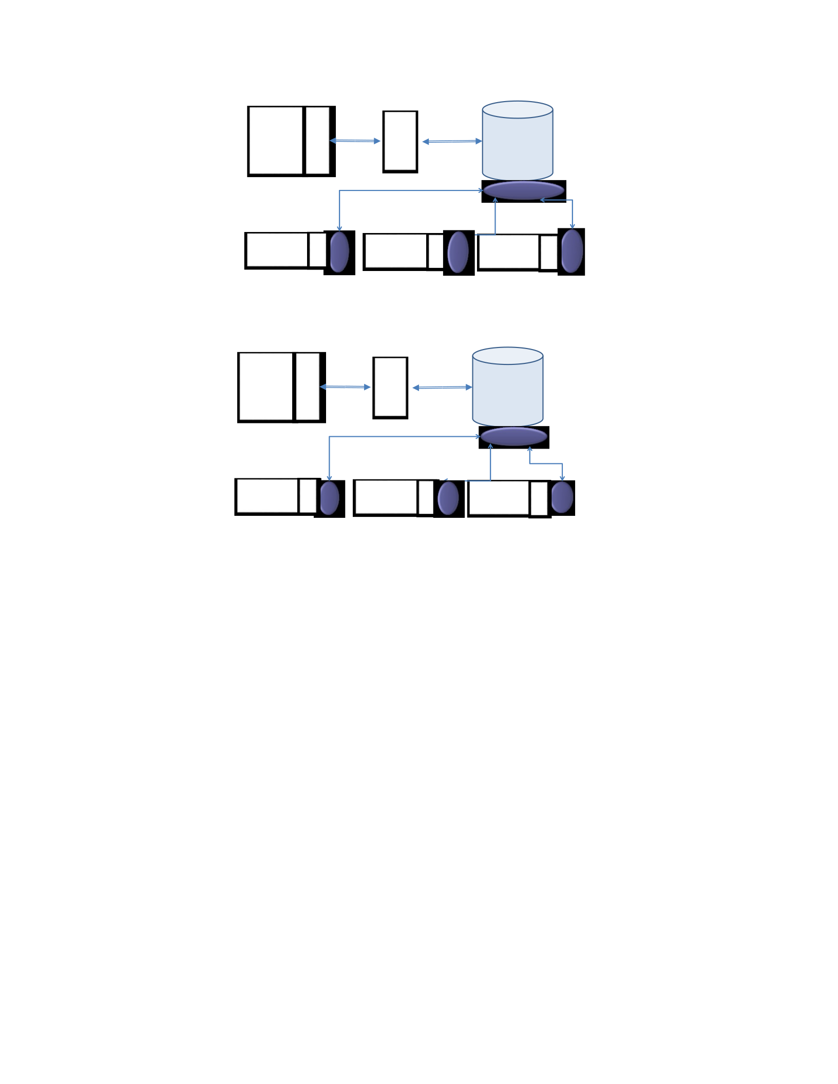
Figure 5.2a. Basic Architecture with Direct Database Access using IFMWK.
Figure 5.2b. Basic Architecture customized with FHIR for IFMWK.
In the second option, shown in Figure 5.3a, the situation is similar to the basic option in
Figure 5.2a, except that there is no direct access to the app repository. Thus, the App.IFMWK
server on the App side is moved in order to directly interact with the App RESTful API. There
are still the HIT.IFMWK servers for OpenEMR/OpenMRS/PHR as in Figure 5.3a. In this option,
the App continues to use the App RESTful API without change. However, the
App.IFMWK.LOAD and App.IFMWK.STORE services transition to become part of the App
RESTful API. That is, each App.IFMWK.READ service of the App RESTful API first calls the
App.IFMWK.LOAD service, which takes an id of the queried instance and: retrieves the related
data from OpenEMR, OpenMRS, or PHR via their IFMWK server. The second call adds
retrieved data into the App repository via another App IFMWK API service using the
OpenEMR OpenMRS
RESTful API
App
Calls to
RESTful API
App
Repository
PHR
APP.IFMWK
API
API
API
OpenEMR OpenMRS
RESTful API
App
Calls to
RESTful API
App
Repository
PHR
APP. FHIR
API
API
API

App.IFMWK.CREATE service. This requires slight programmatic changes and source code
availability (third issue of Section 5.1). The next step in the process calls the
App.IFMWK.READ service of the App RESTful API which retrieves the related data from the
App repository (which is updated with the new data from the HIT system). Similarly, each
App.IFMWK.CREATE service of the App RESTful API first adds the related data into the App
repository. Then, the App.IFMWK.CREATE service of the App RESTful API calls the STORE
service, which takes the newly added data from the App repository via another App.IFMWK API
service (i.e., a App.IFMWK.READ service) and adds them into the OpenEMR, OpenMRS, or the
PHR database, via their IFMWK service. Note that, in this way, while the App and its calls to the
App.IFMWK.RESTful API are not modified, there is a single call is added to either the
App.IFMWK.LOAD or App.IFMWK.STORE services RESTful API. This requires source code
availability of the RESTful API. Figure 5.3b presents a customized Alternative Architecture
applied to the healthcare domain where the FHIR framework is used as an example of an
integration framework for healthcare, with all of the IFMWKs in Figure 5.3a is replaced by FHIR
in Figure 5.3b.
Figure 5.3a. Alternative Architecture with App RESTful API Access using IFMWK.
App
Repository
OpenEMR OpenMRS
RESTful API
App
Calls to
RESTful API
PHR
API
API
API
APP.IFMWK
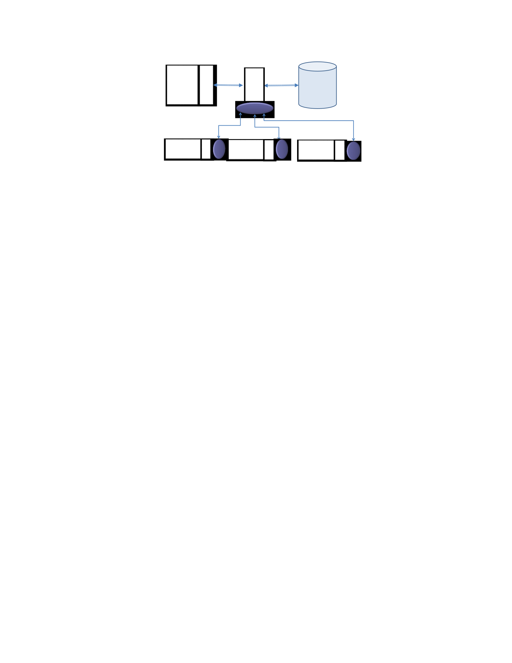
Figure 5.3b. Alternative Architecture customized with FHIR for IFMWK.
In the Radical Architecture, shown in Figure 5.4a, the situation is the same as the alternative
option of Figure 5.3a, but alters the tiers by removing the repository (database). As a result, this
option is a more drastic and involves replacing the App repository and so that it now totally
relies on the HIT systems. This option would move and reconfigure all of the App data under
the control of the HIT system to store and manage all data. This requires a total rewrite of the
code for the App RESTful API with the strong requirement that all service signatures remain
unchanged so as not to impact the App. In this case, every rewritten App RESTful API service
implements a App.IFMWK service to directly call OpenEMR.IFMWK, OpenMRS.IFMWK, or
PHR.IFMWK as required to load/store data as needed. In the Radical Architecture, the services
defined are: App.IFMWK.CREATE, App.IFMWK.READ, App.IFMWK.UPDATE, and
App.IFMWK.DELETE. Source code availability and changing the APIs may be required. This
approach is clearly time and effort prohibitive. Figure 5.4b presents a customized Radical
Architecture applied to the healthcare domain, where the FHIR framework is used as an example
of an integration framework for healthcare, with all of the IFMWKs in Figure 5.4a is replaced by
FHIR in Figure 5.4b.
App
Repository
OpenEMR OpenMRS
RESTful API
App
Calls to
RESTful API
PHR
API
API
API
A .
FHIR
O
MRS.
FHIR
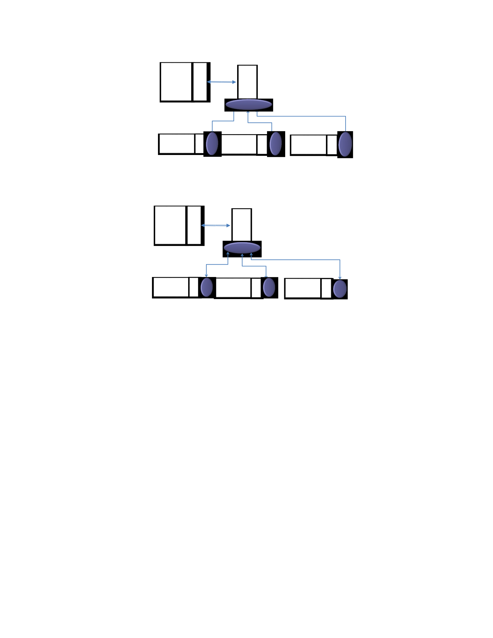
Figure 5.4a. Radical Architecture without a Database using IFMWK.
Figure 5.4b. Radical Architecture customized with FHIR for IFMWK.
5.3 Integration Steps and Processes of Architectural Blueprints
This section presents a discussion of the steps and processes that are necessary to develop the
various IFMWK servers illustrated in Figures 5.2a, 5.3a, and 5.4a for the Basic, Alternative, and
Radical options. The end result is set of guidelines for the architectural blueprints for the
integration of an App application, via a App.IFMWK server that integrates with the App
RESTful API, with multiple HIT systems, via FSICC, and a HIT.IFMWK server that integrates
with the APIs of OpenEMR, OpenMRS, and PHR. The guidelines presented in this section
provides stakeholders with a process to integrate an App with multiple HIT systems via FSICC
using IFMWK servers. This section details the blueprints for the Basic, Figure 5.2.a, Alternative,
OpenEMR OpenMRS
RESTful API
App
Calls to
RESTful API
PHR
API
API
API
APP. IFMWK
OpenEMR OpenMRS
RESTful API
App
Calls to
RESTful API
PHR
API
API
API
A .
FHIR
O
MRS.
FHIR

Figure 5.3.a, and Radical, Figure 5.4.a, architectures. All three of these architectures blueprints
share the common HIT.IFMWK blueprint which involves defining the HIT system data items to
be sent/received and designing a HIT.IFMWK server to facilitate the exchange. The three
architectures have their own specific needs, namely, the App.IFMWK server required at the App
side Repository in Figure 5.2.a, the App.IFMWK server in Figure 5.3.a, and rewriting the
App RESTful API in Figure 5.4.a with a App.IFMWK server. Note that while we are using an
HIT system and the health care domain, this is generalizable to any IT system and associated
domain.
To begin, the common HIT IFMWK Blueprint involves defining the HIT system data items to
be sent/received back and forth via a set of Identified IFMWK Resources to another IFMWK
server or client, and designing a HIT IFMWK server (HIT.IFMWK) with a RESTful API to
facilitate the exchange. The processes of each step that are the guidelines are as:
1. Define the HIT system data items (i.e., for the HIT repositories in Figures 5.2.a, 5.3.a, and
5.4.a) that are needed to be exchanged to/from the App. This step consists of four sub-steps:
a. Identify each single candidate data item (e.g., “patient name” table field) in the HIT
repository that are accessible via an HIT API.
b. For each candidate data item:
Provide a short and clear item name: by reviewing the IFMWK resources, identify
a IFMWK resource, and mapping the candidate data item to the most comparable
data item of the identified IFMWK Resource.
For the candidate data item, if there is no similar item’s name for the identified
IFMWK resource, identify an item of a IFMWK resource that has the same
datatype as the candidate data item.

Provide a brief description that explains the mapping for the case where there is a
comparable IFMWK data item and more importantly, the case where there is only
a comparable IFMWK data type.
c. Group multiple related HIT system data items (e.g., patient name and patient gender) into
a separate and distinct data abstraction (e.g., patient entity). This would make mapping to
an Identified IFMWK Resource clearer by finding the most similar IFMWK resource’s
name.
d. End Result: A set of Identified IFMWK Resources that map to the HIT data entities and
items.
2. Design an HIT.IFMWK server in front of the HIT system API in two sub-steps:
a. A HIT.IFMWK server is designed for all of the Identified IFMWK Resources in Step 1d that
defines a IFMWK API that has CRUD operations for all of the Identified IFMWK Resources
and interacts with the HIT API.
b. Create Classes and CRUD services for all of the Identified IFMWK Resources for the
HIT.
Create an HIT.IFMWK.Controller class that receives requests from the App (or
any other system) and forwards each request to the appropriate Identified IFMWK
Resource class based on the universally unique identifier (UUID) of an Identified
IFMWK Resource.
Create a class for each Identified IFMWK Resource that receives requests from
the IFMWK controller class and performs the requested CRUD service. This class
is defined for each Identified IFMWK Resource as HIT.IFMWK.IFRCName
where IFCRName is the Identified IFMWK Resource Class name. This class
implements four main CRUD services:

•A HIT.IFMWK.IFRCName.Create service that stores an instance of a
IFMWK resource from an external call from another IFMWK server to
create and store new data into the HIT repository. This service takes the
data in as a IFMWK Resource and then converts the data into a format that
can be stored in the HIT repository via a call to one or more HIT API
services. This effectively stores IFMWK Resource data into the HIT
repository. For example, OpenEMR.IFMWK.Patient (the Patient IFMWK
Resource) would call the service of an OpenEMR API that stores the data
into the Patient_data table of OpenEMR’s MySQL database.
•A HIT.IFMWK.IFRCName.Read service that is a request for an instance
of a IFMWK resource from an external call from another IFMWK server
that to read existing data from the HIT repository. This service takes the
request for a IFMWK Resource that requires a call to one or more HIT
API services to retrieve the data from the HIT and create an instance of an
Identified IFMWK Resource to send back. For example,
OpenEMR.IFMWK.Patient (the Patient IFMWK Resource) would call the
service of an OpenEMR API that reads the data from the Patient_data
table and perhaps other tables of OpenEMR’s MySQL database and
creates a FHIR Patient instance.
•An HIT.IFMWK.IFRCName.Update service that receives an instance of a
IFMWK resource from an external call from another IFMWK server to
update existing data into the HIT repository. This service takes the data in
as a IFMWK Resource and then converts the data into a format that can be

stored in the HIT repository via a call to one or more HIT API services
that update an existing instance.
•A HIT.IFMWK.IFRCName.Delete service that receives a request to
remove one or more instances (based on the parameters in the request) of a
IFMWK resource from an external call from another IFMWK server to
delete existing data from the HIT repository. This service takes the request
for a IFMWK Resource and interprets the request to call one or more HIT
API services to delete instance(s).
Note that for healthcare and similar domains in practice, there may be a desire to not implement
either HIT.IFMWK.IFRCName.Update or HIT.IFMWK.IFRCName.Delete services since in
electronical medical records, incorrect data is not deleted, but is marked as incorrect. For
example, an incorrect laboratory test result assigned to the wrong patient can be marked as not
valid.
The Basic Architecture Blueprint, Figure 5.2.a, allows information from the App repository to
be sent/received back and forth via a set of Identified IFMWK Resources to another IFMWK
server or client by designing an App IFMWK server (App.IFMWK) with a RESTful API to
facilitate the exchange. There are three main steps to the guideline: define the App data items,
design the App IFMWK server with the LOAD and STORE services, and reuse the HIT IFMWK
guideline:
1. Define the App data items (i.e., App repository tables’ fields in Figure 5.2.a) needed to
be exchanged with an HIT system. This step consists of four sub-steps in which the first

three processes are identical to the processes of Step 1 of the HIT IFMWK Blueprint with
the data items now referring to the App data items as opposed to the HIT data items.
End Result: A set of Identified IFMWK Resources that map to the App data items.
2. Design the App IFMWK server which consists of the App.IFMWK.LOAD and
App.IFMWK.STORE services. This step has two sub-steps.
a. A App.IFMWK.LOAD service that calls “read” services of an HIT.IFMWK to
retrieve (in IFMWK format) all of the new added data from the HIT repository. Then,
the App.IFMWK.LOAD service converts the retrieved IFMWK resources into a
format that can be stored into App repository via App repository API. This read
occurs upon startup to initialize the App repository with information from HITs.
b. A App.IFMWK.STORE service that calls App repository API to retrieve all of the
new added data in App repository and converts into the IFMWK format. Then, the
App.IFMWK.STORE service simply forwards the converted data to appropriate
HIT.IFMWK.CREATE services which add the new data into the HIT repository. This
store occurs when the mobile app closes to update the HIT repository with
information from App repository.
3. Employ the HIT IFMWK Blueprint.
Recall that the Basic Architecture has access to the source code of the repository. There may be
more than one way to access the repository via Web/cloud services, an API (as with OpenEMR),
or by direct programmatic access to the repository (e.g., a MySQL database). As a result,
App.IFMWK.LOAD and App.IFMWK.STORE services would utilize one of these access modes
in conjunction with calls to HIT.IFMWK CRUD services (e.g.,
OpenEMR.IFMWK.Patient.Read) and take the result of these calls for the identified IFMWK
resources, and parse and put this information to/from App repository.

The Alternative Architecture Blueprint, Figure 5.3.a, also communicates with the common
HIT IFMWK Blueprint as previously described in the last step of the Alternative Architecture
blueprint. There are four main steps to the Alternative Architecture guideline: define the App data
items and design the App IFMWK server (similar to the one in the Basic Architecture Blueprint),
design the LOAD and STORE services, and reuse the HIT IFMWK Blueprint. The processes of
each step are similar to the ones of the Basic Architecture guideline of Figure 5.2.a:
1. Define the App data items (i.e., App repository tables’ fields in Figure 5.3.a) that are
needed to be exchanged with an HIT system. This step consists of four main processes in
which the first three processes are identical to the processes of Step 1 of the HIT IFMWK
Blueprint with the data items now referring to the App data items as opposed to the HIT
data items.
End Result: A set of Identified IFMWK Resources that map to the App data items.
2. Design an App.IFMWK server in front of the App RESTful API in two sub-steps:
a. A App.IFMWK server is designed for all of the Identified IFMWK Resources in Step
1d that defines a IFMWK API that has CRUD operations for all of the Identified
IFMWK Resources and interacts with the HIT.IFMWK server.
b. Create Classes and CRUD services for all of the Identified IFMWK Resources for the
App repository.
A App.IFMWK.IFRCName.Create service that stores an instance of a IFMWK
resource from an external call from another IFMWK server to create and store
new data into the App repository. This takes the data in as a IFMWK Resource
and then converts the data into a format that can be stored in the App repository
via a call to one or more App RESTful API services. This effectively stores

IFMWK Resource data into the App repository. This would be similar to the
OpenEMR example for the HIT.IFMWK server.
A App.IFMWK.IFRCName.Read service that is a request for an instance of a
IFMWK resource from an external call from another IFMWK server that to read
existing data from the App repository. This takes the request for a IFMWK
Resource that requires a call to one or more App RESTful API services to retrieve
the data from the App repository and create an instance of an Identified IFMWK
Resource to send back. This would be similar to the OpenEMR example for the
HIT.IFMWK server.
An App.IFMWK.IFRCName.Update service that receives an instance of a
IFMWK resource from an external call from another IFMWK server to update
existing data into the App repository. This takes the data in as a IFMWK
Resource and then converts the data into a format that can be stored in the App
repository via a call to one or more App RESTful API services, updating an
existing instance.
A App.IFMWK.IFRCName.Delete service that receives a request to remove one
or more instances (based on the parameters in the request) of a IFMWK resource
from an external call from another IFMWK server to delete existing data from the
App repository. This takes the request for a IFMWK Resource and interprets the
request to call one or more App RESTful API services to delete instance(s).
These App.IFMWK CRUD services are called by the App API in order to send
information back and forth in a IFMWK format that can then be shifted to the
HITs via the App.IFMWK.LOAD and App.IFMWK.STORE operations defined in
Step 3.

3. Design the App.IFMWK.LOAD and App.IFMWK.STORE services. These two services
are located between the App.IFMWK server and any HIT system IFMWK server and
have substeps. The HIT.IFMWK CRUD services are used to support these functions.
a. A App.IFMWK.LOAD service that calls “read” services of an HIT.IFMWK to
retrieve (in IFMWK format) the new added data into HIT system. Then, the
App.IFMWK.LOAD service simply forwards the retrieved data to “create”
services of App.IFMWK which adds the new data into the App repository. This
read occurs when the App.IFMWK.IFRCName.Read is called to update the App
repository with information from HITs.
b. A App.IFMWK.STORE service that calls “read” services of the App.IFMWK to
retrieve (in IFMWK format) the new added data in App repository. Then, the
App.IFMWK.STORE service simply forwards the retrieved data to “create”
services of HIT.IFMWK which adds the new data into the HIT repository . This
store occurs after the App.IFMWK.IFRCName.Create is called to update the HIT
repository with information from App repository.
4. Employ the HIT IFMWK Blueprint.
Note that in practice, there may be a desire to not implement either
App.IFMWK.IFRCName.Update or App.IFMWK.IFRCName.Delete since in electronical
medical records, incorrect data is not deleted, but is marked as incorrect. In this case, we may
not want the App to propagate incorrect data into the HIT systems.
Finally, the Radical Architecture Blueprint, Figure 5.4.a, has three main steps: define the App
data items, redesign the App RESTful API, and communicate the IFMWK HIT Blueprint. The
processes of these steps in this guideline are:

1. Define the App data items, see Figure 5.4.a, that are needed to be exchanged with an HIT
system. This step consists of four main processes in which the first three processes are
identical to the processes of Step 1 of the HIT IFMWK guideline with the data items now
referring to the App data items as opposed to the HIT data items.
End Result: A set of Identified IFMWK Resources that map to the App data items.
2. Redesign the App RESTful API to implement App.IFMWK server in two sub-steps:
a. App.IFMWK server is designed for all of the Identified IFMWK Resources in Step 1d that
defines a IFMWK API that has CRUD operations for all of the Identified IFMWK Resources
and interacts with the HIT.IFMWK.
b. Create Classes and CRUD services for all of the Identified IFMWK Resources for the
App.
A App.IFMWK.IFRCName.Create service that receives the new data from the
App, converts it into a format that can be assigned to a IFMWK resource, creates
an instance of the IFMWK resource, and populates the IFMWK resource with the
converted data. After that, this service calls the HIT.IFMWK.IFRCName.Create
service with the IFMWK resource as a parameter.
A App.IFMWK.IFRCName.Read service that receives the id of a IFMWK
resource from the App, invokes the HIT.IFMWK.IFRCName.Read service with
the id as a parameter. After receiving the result in IFMWK format, this service
converts the result into a format that can be used by the App and sends it to the
App.
An App.IFMWK.IFRCName.Update service that is similar to the
App.IFMWK.IFRCName.Create service, however, this service updates the

existing data.
A App.IFMWK.IFRCName.Delete service that receives the id of a IFMWK
resource from the App, calls the HIT.IFMWK.IFRCName.Delete service.
3. Employ the HIT IFMWK Blueprint.
Note that for healthcare and similar domains in practice, there may be a desire to not invoke
either App.IFMWK.IFRCName.Update or App.IFMWK.IFRCName.Delete services for the same
issue discussed above. Also note that there is no need for LOAD and STORE in this Radical
option since there is no repository remaining on the App side of Figure 5.4.a.
In summary, there are a number of observations to make regarding the IFMWK CRUD,
LOAD, and STORE services. The CRUD services are defined to manipulate a single IFMWK
resource that interacts with either the App Repository or the HIT system in order to take
information in IFMWK format and convert it back and forth into the format of the data items in
the Repository/HIT. This requires creating, reading, updating or deleting to/from the
Repository/HIT using the respective API. For the read service on a particular resource, the
information is retrieved using services of the API in the native format of the Repository/HIT and
converted to the common format of the IFMWK resource so that it can be delivered through the
IFMWK.READ service. For the update service on a particular resource, the resource comes in
the common format and the update service would extract out the data items so that they can be
assembled to call the appropriate Repository/HIT API services. The create and delete services
would work in a similar fashion. The LOAD and STORE services differ in that they deal with
multiple IFMWK resources. For STORE, a set of IFMWK resources is passed in via a common
format and these resources are extracted and assembled to allow multiple API services to be
called to store the information in the destination format of the Repository or HIT system. For

LOAD, multiple API services from the repository/HIT are called to gather information that is
then converted and assembled into the appropriate IFMWK resources. The resource concept of
IFMWK facilitates information exchange. However, there is still extraction/conversion required
to transition the data from the source to the sharable IFMWK format.
5.4 Blueprint Prototype Applied to the Healthcare Scenario
This section presents a proof-of-concept prototype that demonstrates the ability of a select
subset of the Blueprints from Sections 5.2 and the usage of the corresponding guidelines in
Section 5.3, that can be applied to the healthcare scenario from Section 2.4. This is by applying
the blueprint process on two integration cases: (case 1) integrate the CT2 mHelth app into the
OpenEMR HIT system via FSICC (Chapter 3); and (case 2) integrate the ShareMyHealth mHelth
app into the MyGoogle HIT system via FSICC (Chapter 3). In the process, we fully illustrate the
application of two of the three architectures blueprints (Basic, Alternative, Radical) and the HIT
IFMWK blueprint to the two integration cases above. The end result of this process is that the
CT2 and ShareMyHealth client Apps are able to utilize the services of the OpenEMR and
MyGoogle systems, respectively, via the global services of the FSICC. The remainder of this
section is organized into two parts. In Section 5.4.1, we detail the rational of the chosen
architectural options for integrating the two mHelth apps into the two HIT systems (cases 1 and
2) using: the Alternative architecture to integrate CT2 app into OpenEMR, see Figure 5.3b in
Section 5.2; and the Basic architecture to integrate ShareMyHealth app into MyGoogle, see
Figure 5.2b in Section 5.2. Then, in Section 5.4.2, we apply the three architectural options and
associated guidelines of Section 5.3 to describe the integration steps and processes for integration
cases 1 and 2.

5.4.1 Integrating Architectural Options for CT2 and ShareMyHealth
This section explains the rationale that influenced the selection of the most suitable integration
option for the two mHealth apps/clients CT2 and ShareMyHealth and two HIT systems
OpenEMR and MyGoogle for the three architecture options, Basic Figure 5.2, Alternative Figure
5.3, Radical Figure 5.4, discussed in Section 5.2. Note that we made an assumption that the
FSICC has already been built and published its own IFMWK server (FSICC.FHIR) so that
different apps and systems can integrate via the FSICC FHIR server. To begin, for the CT2
mHealth app (case 1), the Alternative architecture was chosen and reconfigured, as shown in
Figure 5.5, based on a number of reasons. First, we had significant human knowledge of the CT2
mHealth app and RESTful API and maintain the MySQL database. Second, we had the source
code available for: the App, the RESTful API, and the MySQL database. This meant that we had
the ability to do any of the three architectural options, but we chose the Alternative architecture
we were able to maintain the processing and flow of the CT2 app through the RESTful API to the
database. To apply the Alternative architecture, two FHIR servers, as shown in Figure 5.5, are
created: one for the CT2 RESTful API (CT2.FHIR) and another one for the OpenEMR API
(OpenEMR.FHIR). These two FHIR servers are utilized for exchanging data between CT2 and
OpenEMR via FSICC. Moreover, from the CT2 App’s perspective, the signatures of the services
of the CT2 RESTful APIs remained unchanged, while from the CT2 API’s perspective, the
interaction with the app and the database remained unchanged. For example, when a user
interacts with the CT2 App to view and modify a concussion incident for a student, the process
transitions from the user request to an API call to a database access to a returned concussion
incident. The only change in the process is at the start when a user requests a concussion incident
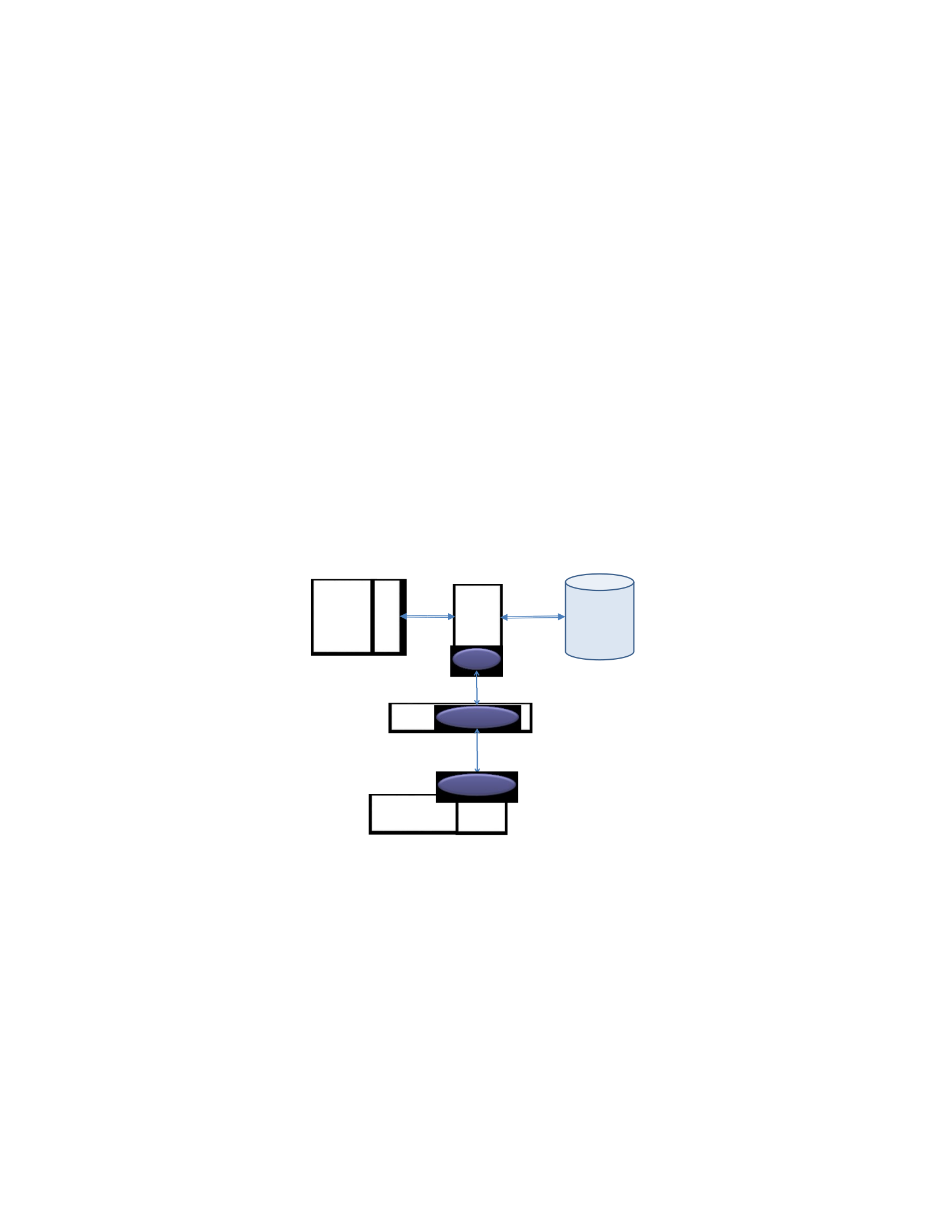
for the student and at the end when a user stores the modified concussion incident for a student.
In both situations, the FHIR server of the CT2 RESTful API intercepts and retrieves/stores the
concussion incident to OpenEMR via FSICC. When the incident is loaded from OpenEMR.FHIR
via FSICC.FHIR, a temporary copy is made in the CT2 database and all of the changes that occur
via the RESTful API are made to the database on that temporary copy. The final store sends the
temporary copy through the CT2.FHIR and FSICC.FHIR servers to OpenEMR.FHIR. We
decided against the Radical Architecture since we didn’t want to make the substantial changes
that would be required to migrate all of the information in the CT2 database to OpenEMR. This
would have included registration information, permissions (who can see/modify which
concussion incidents), etc., that would have been difficult to directly store in OpenEMR.
Figure 5.5. Alternative Architecture for Integrating CT2 into OpenEMR via FSICC.
For case 2, the Basic architecture was chosen and reconfigured for the ShareMyHealth (SMH)
mHealth app as shown in Figure 5.6. For the SMH app, the source code is available for: the app,
the RESTful API, and the repository. Based on this, we are able to utilize any of the three
architectural options. However, we decide to apply the Basic architecture since we want to keep
the SMH’s architecture unchanged as much as we can. To apply the Basic architecture two FHIR
FSICC
CT2
RESTful API
CT2
mHealth
App
Calls to
RESTful API
CT2
App
Database
CT2.
FHIR
FSICC.FHIR
OpenEMR API
O EMR.
FHIR
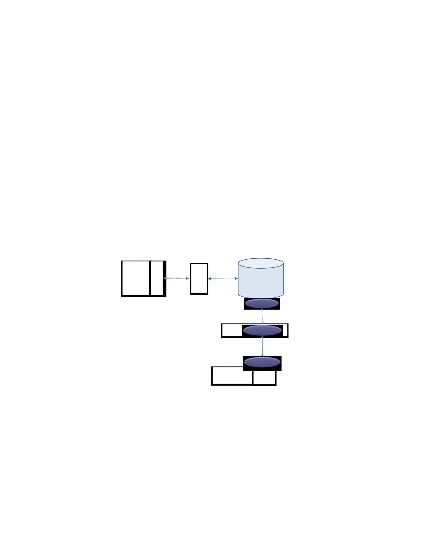
servers as shown in Figure 5.6 are created: one for the SMH repository (SMH.FHIR) and another
one for the MyGoogle API (MyGoogle.FHIR). These two FHIR servers, in addition to
FSICC.FHIR server, are utilized for exchanging data between SMH and MyGoogle via FSICC.
The Basic architecture also requires SMH to create two services into FHIR: SMH.FHIR.LOAD
which retrieves related data from MyGoogle, via FSICC.FHIR, in the FHIR format; and,
SMH.FHIR.STORE which grabs the data from the SMH repository, via an SMH FHIR service,
and sends them to MyGoogle via FSICC.FHIR. These two services are meant to be periodically
called to ensure that the repositories at both sides are updated. Note that interactions from both
the SMH via its RESTful API and the SMH RESTful API to the SMH repository are not changed
The Alternative and Radical architectures are not suitable for the same reason stated for case 1.
Figure 5.6. Basic Architecture for Integrating SMH into MyGoogle via FSICC.
5.4.2 Applying Integration Steps and Processes
In this section, we apply the guidelines of the Blueprint of Sections 5.2 and 5.3 to enumerate
the integration steps and processes for integration cases 1 and 2 from Section 5.4.1. For case 1 in
Section 5.4.1, we know that we need to integrate the CT2 mHelth app into the OpenEMR HIT
RESTful API
SMH
Calls to
RESTful API
SMH
Repository
SMH.FHIR
FSICC FSICC.FHIR
MyGoogle API
M Google.
FHIR

system via FSICC, see Figure 5.5, using two blueprints: the Alternative architecture to create the
CT2.FHIR server, and the HIT FHIR blueprint to create OpenEMR.FHIR server. First, the steps
of the Alternative architecture from Section 5.3 can be reformulated as:
1. Define the CT2 mHealth data items from the CT2 that need to be exchanged with
OpenEMR via FHIR to yield the Identified FHIR resources for CT2.
2. Design a CT2.FHIR server in front of the CT2 RESTful API.
3. Design CT2.FHIR CRUD services (CT2.FHIR.IFRCName.Create,
CT2.FHIR.IFRCName.Read, CT2.FHIR.IFRCName.Update, and
CT2.FHIR.IFRCName.Delete) in addition to CT2.FHIR.LOAD and
CT2.FHIR.STORE services that extend the CT2 RESTful API so that the exchange via FHIR can
occur with OpenEMR.
4. Employ the HIT FHIR Blueprint.
Then for the HIT FHIR blueprint, the two steps can be reformulated as:
1. Define the OpenEMR system data items that are needed to be exchanged to/from the
CT2 mHealth app via FHIR to yield the Identified FHIR resources for OpenEMR.
2. Design an OpenEMR.FHIR server in front of the OpenEMR system API.
The main focus for both of these blueprints is in Step 1 of each which focuses on the way to
identify the data items that need to be exchanged from each side via FHIR. This requires a
designer to understand the correspondence between two sets of information:
•The data items of the CT2 concussion MySQL database and the relevant FHIR resources
that can be chosen to store them.
•The data items of the OpenEMR MySQL database and the relevant FHIR resources that
can be chosen to store them.

The challenge is to consider these correspondences simultaneously to understand the way that the
data items of the concussion app can be mapped via FHIR resources to the data items of
OpenEMR. The end result is a set of Identified FHIR resources that serves as the common layer
to facilitate the exchange of data between CT2 and OpenEMR via FHIR services.
To begin this analysis process, in Step 1 of the Alternative Architecture Blueprint from Section
5.3, we start by identifying the four key data items of CT2 mHealth that are in four tables of the
MySQL Concussion database, namely: the Students table that tracks basic information on
students (e.g., demographics, school, etc.); the Incidents table that tracks information on the
concussion incident (e.g., when concussion happened, initial symptoms, etc.); the
Incident_Locations table that tracks where the concussion occurred (e.g., at school, at sports
field, at home, etc.); and, the Incident_Lingering_Symptoms table that tracks concussion
symptoms observed in the days following the concussion (e.g., dizzy, nauseous, etc.). These four
tables are shown in Figure 5.7.
Students
student_id
first_name
middle_name
last_name
suffix
Email
student_number
school_id
incidents
incident_id
incident_reference_id
student_id
incident_location_id
incident_location_details
sport_id
contact_mechanism_id
impact_location_id
Removed
removed_by_user_id
tool_id
symptom_comments
Date
school_id
reporting_user_id
head_gear_usage
parents_notified
loss_conciousness
incident_locations
location_id
incident_lingering_symptoms
record_id

title
description
symptom_id
Figure 5.7. CT2 Data Items of Interest.
Given the understanding of this information, we can continue the analysis process with Step 2
of the Alternative Architecture Blueprint in Section 5.3 to determine the Identified FHIR
Resources that can be utilized to capture the information from Figure 5.7. To track concussion
data on a student, we can use the FHIR resources (Health Level 7, Fast Health Interoperable
Resources, 2016) as shown in Figure 5.8. The Identified FHIR Resources are: Patient, Condition,
Encounter, and Observation. Specifically: Patient to track demographic and other basic
information on patients (students that suffer concussions); Condition to track a medical
condition, in our case a concussion; Encounter to track the different times that changes are made,
in our case, as the concussion incident is tracked over time such as lingering symptoms; and
Observation to track symptoms and lingering symptoms of patients (students). Examining the
MySQL tables of the CT2 database in comparison to the aforementioned FHIR resources, we can
establish a correspondence or mapping between them as shown in Figure 5.9. In this mapping of
CT2 database MySQL tables FHIR resources we have: students Patient; incidents
Condition; incident_lingering_symptoms Observations; and incident_locations Encounter.
Id
name.given
name.given
name.family
name.suffix
Telecom
Identifier
managingOrganization
Condition
id
Code
Patient.reference
Encounter.id
Notes
category
Evidence.id
bodySite
clinicalStatus
Asserter
Abatement
evidence.detail
dateRecorded
identifier
Encounter.reference
Evidence.detail
Evidence.FormatComment
Evidence.hashCode
Encounter
Id
location
reason
Observation
id
Encounter.id
Subject.id
Performer.id
issued
related.type

status
value
Figure 5.8. FHIR Resources of Interest.
Patient
Id
name.given
name.given
name.family
name.suffix
Telecom
Identifier
managingOrganization
incidents
incident_id
incident_reference_id
student_id
incident_location_id
incident_location_details
sport_id
contact_mechanism_id
impact_location_id
Removed
removed_by_user_id
tool_id
symptom_comments
Date
school_id
reporting_user_id
head_gear_usage
parents_notified
loss_conciousness
Condition
id
Code
Patient.reference
Encounter.id
Notes
category
Evidence.id
bodySite
clinicalStatus
Asserter
Abatement
evidence.detail
dateRecorded
identifier
Encounter.reference
Evidence.detail
Evidence.FormatComment
Evidence.hashCode
Figure 5.9. Mapping from CT2 to/from FHIR.
Now, let’s turn the discussion to Steps 1 and 2 of the HIT FHIR Blueprint from Section 5.3
that involves an analogous process to Figures 5.7, 5.8, and 5.9, with the data items of OpenEMR.
Since we have already arrived at the FHIR resources needed for mapping, Figure 5.8, we can
reuse the aforementioned Identified FHIR Resources to assist in the identification of the
appropriate four data items in OpenEMR in Figure 5.10, namely: the Patient_Data table that
tracks patient (student) demographic data; the Lists table that tracks issues related to medical
problems, etc. (concussion medical problem); the Form_Encourter table that tracks the event
involved with the patient visiting (student seeing nurse); and, the Procedure_Order_Code table
that tracks different codes associated with procedures. These four items correspond to the FHIR
Resources as shown in Figure 5.11. This mapping has: Patient_data Patient; Lists Condition;
procedure_order_code Observations; and form_encounter Encounter.
Students
student_id
first_name
middle_name
last_name
suffix
Email
student_number
school_id
incident_locations
location_id
title
description
incident_lingering_symptoms
record_id
symptom_id
Encounter
Id
location
reason
Observation
id
value
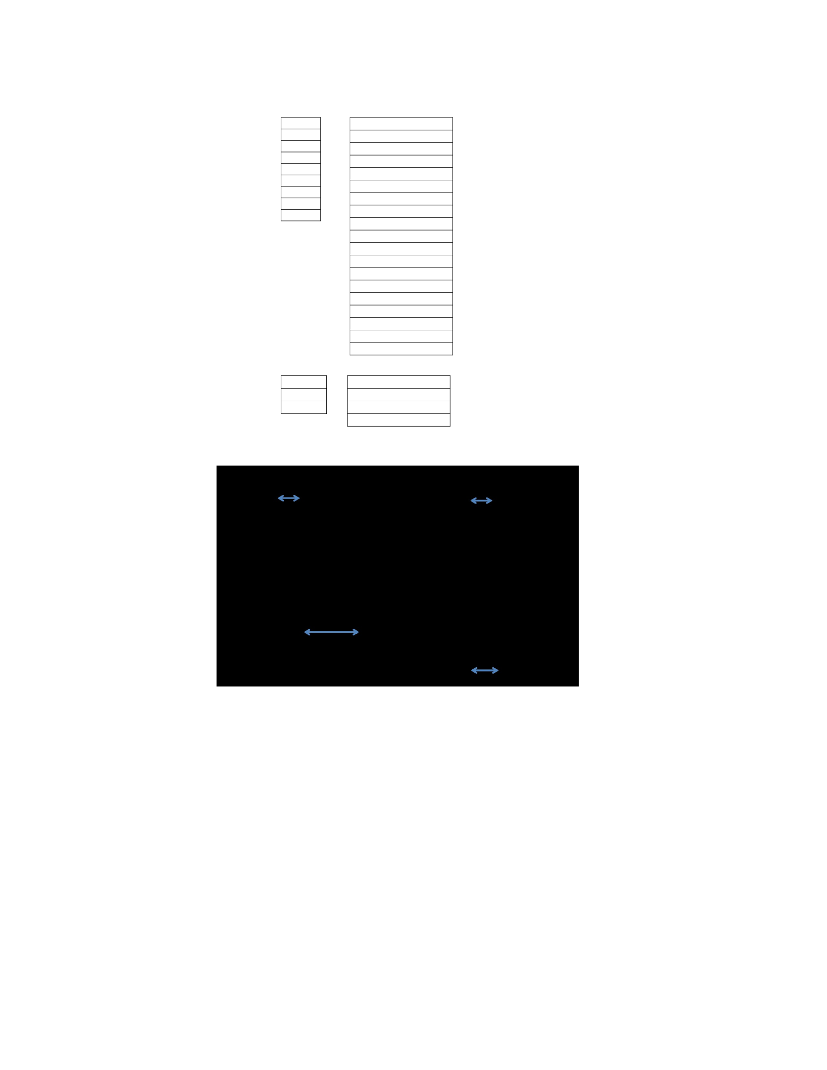
Patient_data
Pid
Fname
Mname
Lname
Title
Email
Pubpid
referrerID
Lists
Id
Title
Pid
injury_type
Extrainfo
Activity
injury_grade
injury_part
Occurance
User
reinjury_id
Comments
Begdate
Destination
Referredby
Type
Classification
Diagnosis
procedure_order_code
procedure_order_id
procedure_order_seq
form_encounter
id
facility
reason
Figure 5.10. The OpenEMR Data Items of Interest.
Figure 5.11. Mapping from OpenEMR to/from FHIR.
The last step of the HIT FHIR Blueprint is the creation of the OpenEMR.FHIR server. As
described in the HIT FHIR Blueprint and based on the selected FHIR resources in the provisos
steps, we created a FHIR controller class which receives requests from the CT2 mHealth app, or a
third-party such as FSICC, and sends the request to the appropriate OpenEMR FHIR resource
class along with any parameters. We also created four OpenEMR Identified FHIR resources
classes (i.e., Patient, Condition, Observation, and Encounter) as shown in the bottom right of

Figure 5.12. For each OpenEMR FHIR resources classes, we defined:
OpenEMR.FHIR.IFRCName.Create and OpenEMR.FHIR.IFRCName.Read). The
OpenEMR.FHIR.IFRCName.Create service receives an instance of a FHIR resource that
involves new data, of a specific class, converts the data into a format that can be stored in the
OpenEMR system, and sends the converted data to a create service of the OpenEMR system API
that stores the data into the OpenEMR database. The OpenEMR.FHIR.IFRCName.Read service
retrieves data from the OpenEMR database via a read service of the OpenEMR system API,
creates a new instance of the specific FHIR resource class, and converts the retrieved data into a
format that can be assigned to the identified OpenEMR FHIR resource instance. Following that,
this service populates the corresponding OpenEMR FHIR resource instance with the converted
data, and sends this FHIR resource instance to the CT2 mHealth app, or a third-part such as
FSICC. This service is also designed to retrieve all of the related data on the specific data item if
there are no passed parameters.
Finally, the remaining step of the Alternative Architecture Blueprint in Section 5.3 is to
implement the CT2.FHIR server. As described in the Alternative Architecture Blueprint and based
on the selected FHIR resources, we created a FHIR controller class which receives requests from
the CT2.FHIR.LOAD and CT2.FHIR.STORE services; and sends the request to the appropriate
CT2 FHIR resource class along with any parameters. We also created four CT2
Identified FHIR resources classes (i.e., Patient, Condition, Observation, and Encounter) at the top
right of Figure 5.12 shows. For each of these CT2 FHIR resources classes, we created two main
CRUD service, CT2.FHIR.IFRCName.Create and CT2.FHIR.IFRCName.Read and
CT2.FHIR.LOAD and CT2.FHIR.STORE services. The CT2.FHIR.IFRCName.Create service
receives an instance of a FHIR resource with new data, converts the data into a format that can be

stored in the CT2 database, and sends the converted data to the CT2 RESTful API (a create
service) which stores the data into the CT2 database. The CT2.FHIR.IFRCName.Read service
retrieves data from the CT2 database via a CT2 RESTful API (a read service), creates a new
instance of related CT2 FHIR resource class, and converts the retrieved data into a format that can
be assigned to the CT2 FHIR resource instance. After that, the CT2.FHIR.IFRCName.Read
populates the CT2 FHIR resource instance with the converted data, and finally sends this FHIR
resource instance to the request source. The CT2.FHIR.IFRCName.Read service also retrieves all
of the related data about specific data item if there are no passed parameters. The
CT2.FHIR.LOAD service takes an id of the queried CT2.FHIR resource instance, retrieves the
related data from the OpenEMR system via OpenEMR.FHIR and FSICC.FHIR servers, and adds
retrieved data into the CT2 database via another CT2 FHIR service (i.e., the
CT2.FHIR.IFRCName.Create service). Finally, the CT2.FHIR.STORE service calls the
CT2.FHIR.IFRCName.Read service to retrieve (in FHIR format) all of the new added data in
CT2 database. Then, the CT2.FHIR.STORE service simply sends the retrieved data to “create”
services of OpenEMR.FHIR, via the FSICC.FHIR server, which adds the new data into the
OpenEMR system.
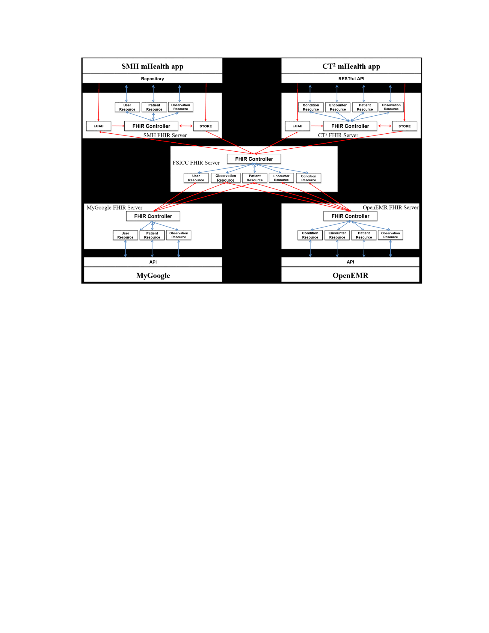
Figure 5.12. Combined Result of the Two Blueprints.
From Section 5.4.1, we know that, for case 2, we need to integrate the SMH mHelth app into
the MyGoogle HIT system via FSICC, see Figure 5.6, using: the Basic architecture blueprint to
create the SMH.FHIR server, and the HIT FHIR blueprint to create MyGoogle.FHIR server.
First, the steps of the Basic architecture can be reformulated as:
1. Define the SMH mHealth data items from the SMH’s repository that need to be
exchanged with MyGoogle via FHIR to yield the Identified FHIR resources for SMH.
2. Design a SMH.FHIR server in front of the SMH repository that includes the two
service SMH.FHIR.LOAD and SMH.FHIR.STORE so that the exchange via FHIR
can occur with MyGoogle.
3. Employ the HIT FHIR Blueprint.

Then, for the HIT FHIR blueprint, the two steps can be reformulated as:
1. Define the MyGoogle system data items that are needed to be exchanged to/from the
SMH mHealth app via FHIR to yield the Identified FHIR resources for MyGoogle.
2. Design an MyGoogle.FHIR server in front of the MyGoogle system API.
Similar to case 1, we start by performing Step 1 of the Basic Architecture Blueprint. Specifically,
we identify the three key data items of SMH mHealth that are in three tables of the SMH
repository, namely: the Measurements table that tracks fitness data of each patient (e.g., height,
weight, steps, etc.); the Patients table that tracks basic information on patients (e.g.,
demographics, gender, etc.); and, the Users table that holds information on SMH’s users (e.g.,
user_id, user_name, etc.). These three tables are shown in Figure 5.13.
Patients Measurements
patient_id measure_id
first_name measure_name
middle_name measure_type
last_name value
Email date
Users
user_id
user_name
Password_hash
Figure 5.13. SMH Data Items of Interest.
Given the understanding of this information, we can continue the analysis process with Step 2
of the Basic Architecture Blueprint to determine the Identified FHIR Resources that can be
utilized to capture the information from Figure 5.13. To track measurement data on a patient we
can use the FHIR resources as shown in Figure 5.14: Observation, Patient, and User.
Specifically: Observation to track measurement of patients; Patient to track demographic and
other basic information on patients; and, User to maintain users’ data. Examining the tables of
the SMH repository in comparison to the aforementioned FHIR resources, we can establish a

correspondence or mapping between them as shown in Figure 5.15. In this mapping of SMH
repository tables FHIR resources, we have: Measurements Observation; Patients
Patient; and Users User.
Patient Observation
Id Id
Name.given Note
Name.given Type
Name.family Value
Telecom Issued
Users
Id
Name
Note
Figure 5.14. FHIR Resources of Interest.
Figure 5.15. Mapping from SMH to FHIR.
For the HIT FHIR Blueprint, we now discuss Steps 1 and 2 that are similar to the processes in
Figures 5.13, 5.14, and 5.15, with the data items of MyGoogle. Since we have already arrived at
the FHIR resources needed for mapping, Figure 5.14, we can reuse the aforementioned Identified
FHIR Resources to assist in the identification of the appropriate three data items in MyGoogle in
Figure 5.16, namely: the DataSources table that tracks fitness data of each patient (e.g., height,
weight, steps, etc.); the Patients table that tracks patient demographic data; and, the Users table
Patient
Id
Name.given
Name.given
Name.family
Telecom
Observation
Id
Note
Type
Value
Issued
User
Id
Name
Note
Patients
patient_id
first_name
middle_name
last_name
Email
Measurements
measure_id
measure_name
measure_type
value
date
Users
user_id
user_name
Password_hash

that holds about MyGoogle users. These three items correspond to the FHIR Resources as shown
in Figure 5.17. In the mapping of MyGoogle data items FHIR resources we have:
DataSources Observation; Patients Patient; and Users User.
Patients DataSources
p_id datasource_id
f_name datasource_name
m_name datasource_type
l_name value
Email date
Users
u_id
u_name
Psswrd_hash
Figure 5.16. MyGoogle Data Items of Interest.
Figure 5.17. Mapping from MyGoogle to FHIR.
The last step of the HIT FHIR Blueprint is the creation of the MyGoogle.FHIR server. As
described in the HIT FHIR Blueprint and based on the selected FHIR resources in the provisos
steps, we created a FHIR controller class which receives requests from the SMH mHealth app, or
a third-party such as FSICC, and sends the request to the appropriate MyGoogle FHIR resource
class along with any parameters. We also created three MyGoogle Identified FHIR resources
classes (i.e., Patient, Observation, and User) as shown in the bottom left of Figure 5.12. For each
Patient
Id
Name.given
Name.given
Name.family
Telecom
Observation
Id
Note
Type
Value
Issued
User
Id
Name
Note
Patients
p_id
f_name
m_name
l_name
Email
DataSources
datasource_id
datasource_name
datasource_type
value
date
Users
u_id
u_name
Psswrd_hash

of these MyGoogle FHIR resources classes, we defined: MyGoogle.FHIR.IFRCName.Create and
MyGoogle.FHIR.IFRCName.Read). The MyGoogle.FHIR.IFRCName.Create service
receives an instance of a FHIR resource that involves new data, of a specific class, converts the
data into a format that can be stored in MyGoogle system, and sends the converted data to a
create service of the MyGoogle system API that stores the data into the MyGoogle database. The
MyGoogle.FHIR.IFRCName.Read service retrieves data from the MyGoogle database via a read
service of MyGoogle system API, creates a new instance of the specific FHIR resource class, and
converts the retrieved data into a format that can be assigned to the identified MyGoogle FHIR
resource instance. Following that, this service populates the corresponding MyGoogle FHIR
resource instance with the converted data, and sends this FHIR resource instance to the SMH
mHealth app, or a third-part such as FSICC. This service is also designed to retrieve all of the
related data on the specific data item if there are no passed parameters.
Finally, the remaining step of the Basic Architecture Blueprint is to implement the SMH.FHIR
server. As described in the Basic Architecture Blueprint and based on the selected
FHIR resources, we created a FHIR controller class which receives requests from the
SMH.FHIR.LOAD and SMH.FHIR.STORE services and sends the request to the appropriate
SMH FHIR resource class along with any parameters. We also created three SMH Identified
FHIR resources classes (i.e., Patient, Observation, and User) at the top left of Figure 5.12 shows.
Then, we created the two services: SMH.FHIR.LOAD and SMH.FHIR.STORE. The
SMH.FHIR.LOAD service retrieves all related data from the MyGoogle system via
MyGoogle.FHIR and FSICC.FHIR servers, and adds retrieved data into the SMH repository.
Finally, the SMH.FHIR.STORE service retrieves, in FHIR format, all of the new added data in

SMH repository. Then, the SMH.FHIR.STORE service simply sends the retrieved data to
“create” services of MyGoogle.FHIR, via the FSICC.FHIR server, which adds the new data into
the MyGoogle system.
Note that the FSICC.FHIR, middle of Figure 5.12, has five resources: Observation, Patient,
Encounter, Condition, and User. These resources were selected as a result of FHIR resources
selection of both sides: CT2 and OpenEMR require Observation, Patient, Encounter, and
Condition FHIR resources on the right side of Figure 5.12; and, SMH and MyGoolge require
Observation, Patient, and User FHIR resources on the left side of Figure 5.12. Also note that the
role of FSICC.FHIR server simply is to send the FHIR instances back and forth between the
associated clients and systems. That is, between CT2 and OpenEMR FHIR servers on one side;
and between SMH and MyGoogle FHIR servers on the other side.
5.5 Related Work
This section reviews two efforts that illustrate FHIR design and implementation: enabling
better interoperability for healthcare (Kasthurirathne, Mamlin, Kumara, Grieve, & Biondich,
2015) and applying FHIR in an integrated health monitoring system (Franz, Schuler, & Kraus,
2015). The work in (Kasthurirathne, Mamlin, Kumara, Grieve, & Biondich, 2015) provided a
new API module for OpenMRS system that has been built using FHIR. The processes of
designing and developing the OpenMRS FHIR API included: design a framework that assists in
adding FHIR-based API for OpenMRS; select a third party FHIR library to implement FHIR
resources creation and validation; develop a FHIR-based API for the OpenMRS system; and,

implement the search service of a number of FHIR resources that are capable of retrieve data
from the OpenMRS system. The architecture of the presented FHIR module consists of two
layers: the FHIR web layer which mainly retrieves FHIR resources from the FHIR API layer and
the FHIR API layer that basically models and validates FHIR resources. The initial prototype of
the FHIR controller interacted with the Patient and Observation resources with a middle layer
that transitions information to/from OpenMRS. This effort is similar to our work on architectural
blueprints guidelines as both works presented steps to design and develop an integration
framework in front of systems that facilitates system interoperability. However, their effort was
focus on the FHIR standard, and as a result is limited to the healthcare domain and only
highlighted the main steps of implementing a HAPI FHIR API without providing a detailed
discussion on such steps. Furthermore, their effort presented an integration option, similar to our
Radical Architecture Blueprint, that extended OpenMRS system with FHIR API. In contrast to
this effort, our approach provided detailed steps and process of designing and implementing an
integration framework that can be applied to any integration framework of any domain including
FHIR and HAPI FHIR.
The work of (Franz, Schuler, & Kraus, 2015) presented an extension to a health monitoring
system using FHIR to enable interoperability between medical devices and HIT systems. The
health monitoring system consists of an aggregation manager module which is a mobile device
and a telehealth service center module which is a server. These two modules were extended by
adding components, which are implemented using FHIR, to enable their integration. The
aggregation manager module was extended with two services: FHIROBSMessageSender which
sends the measured data as Observation FHIR resource to the telehealth service center module;

and, FHIRDORMessageSender that sends DeviceObservationReport FHIR resource to the
telehealth service center module. The telehealth service center module was extended with two
services: OBSController and DORController which receive Observation and
DeviceObservationReport FHIR resources respectively from the aggregation manager module.
This effort is similar to our work on architectural blueprints guidelines as both works
successfully applied and implemented an integration framework to extend different systems and
make such systems more interoperable. However, this effort discussed only one integration
option, similar to our Alternative Architecture Blueprint, that was specific to the reported effort.
In contrast, our approach provided a generalizable integration framework that can be applied to
any integration framework of any domain including FHIR and HAPI FHIR.
Chapter 6 Global Security Policy Generation and Dynamic
Enforcement for FSICC
In this chapter, we discuss GSP (Global Security Policy) Generation and GAPI (Global API)
Generation and Global Security Policy and Global API Utilization and Security Enforcement
which was shown in the 4th and 5th horizontal boxes, respectively, in Figure 1.3 of Chapter 1. As
described earlier in Chapter 3, the global security policy of FSICC is generated by cloud
computing capability two, Local Security Policies Registration to Yield Global Security Policy, of
FSICC, that utilizes two components of FSICC: Security Policy Mapping, see the Security
Policy Mapping box of FSICC in Figure 1.1 form Chapter 1; and Global Security Policy, see the
Global Security Policy box of FSICC in Figure 1.1. Specifically, capability two of FSICC
enables any system, which corresponds to the Systems box in the Involved Parties component at

the top of Figure 1.2, to register the system’s security policy that can be any combination of
RBAC, MAC, and DAC, which corresponds to the Access Control Models component in Figure
1.2. For RBAC, the system registers to provide: the defined roles, the defined services, the role-
services authorization list, the role hierarchy, the defined users, the user-role assignment list. For
MAC, the system registers to provide: the defined services along with a classification for each
service; and the defined users in which each user has a clearance, a read property and a write
property. Finally, for DAC, the system registers to provide: the role delegation list and the
clearance delegation list. In further support of this chapter, we utilize the Unified Cloud
Computing Access Control Model (UCCACM), from Chapter 4, which has a set of definitions
for global security policy generation and utilization (see Defns. 41-48 in
Section 4.6). These definitions ensure that such global security policy can control access to a set
of global services that are generated using one or more of integration architecture blueprints:
Basic Architecture, Alternative Architecture, or Radical Architecture from Chapter 5. In addition,
from the enforcement perspective to check whether applications are allowed to call particular
services, UCCACM has definitions for RBAC interceptors (see Defns. 50-52 in
Section 4.7.1), MAC interceptors (see Defns. 53-56 in Section 4.7.2), and DAC interceptors (see
Defns. 57-60 in Section 4.7.3).
Based on this, this chapter has two main parts. The first part presents a set of algorithms for
generating the global security policy of FSICC; this partially addresses Contribution EC-C:
Security Mapping/Enforcement Algorithms and SSEP, from Section 1.5, by focusing on Security
Mapping/Enforcement Algorithms, this is represented by the Global Security Policy Generation
box of the GSP (Global Security Policy) Generation and GAPI (Global API) Generation
horizontal box in Figure 1.3 from Chapter 1. To support this, we present a set of algorithms to

implement the concepts of global security policy definition and mapping of services to/from
mixed clients and pure and mixed systems. These algorithms support: global RBAC generation,
global MAC generation, global DAC generation, and global policies combination. The second
part introduces and discusses three security interceptors for RBAC, MAC, and DAC (which are
the implementation of the UCCACM for the FSICC) via a number of checks and an algorithmic
approach for each interceptor; this addresses Contribution EC-D: Dynamic
Enforcement via Intercepting Process from Section 1.5, this is represented by the Security
Enforcement via Interceptors box of the GSP (Global Security Policy) and GAPI (Global API)
Utilization and Security Enforcement horizontal box in Figure 1.3. This is accomplished by
presenting a set of programmatic RBAC, MAC, and DAC interceptors, which are the
implementation of the definitions in Section 4.7 for UCCACM, that intercept any request to
access FSICC’s global services, that are generated using one or more of integration architecture
blueprints from Chapter 5. To support this, a number of security interceptors (i.e., RBAC
Interceptor, MAC Interceptor, and DAC Interceptor) are presented to enforce such global security
policy on the users’ access requests.
In the remainder of this chapter, we discuss Global Security Policy Generation and Dynamic
Enforcement for FSICC in three sections. In Section 6.1, a set of security policy integration
algorithms are presented and discussed for: global RBAC generation, global MAC generation,
global DAC generation, and global policies combination. In Section 6.2, we demonstrate the
realization of UCCACM of FSICC in HAPI FHIR utilizing the healthcare scenario of Section 2.4
of Chapter 2 that involves the implementation of HAPI FHIR APIs and its server interceptor to
support UCCACM checks with three different algorithms to support three different HAPI FHIR
interceptors: RBAC interceptor, MAC interceptor, and DAC interceptor. Moreover, the

interceptor discussions are supported by two access scenarios. Section 6.3 presents and discusses
related work in both security policy integration and enforcing security policies on FHIR API.
Note that the work in this chapter has been published in (Baihan, M., et al., 2017).
6.1. Security Policy Integration Algorithms
To start this discussion, Figure 6.1 shows architecture for global security policy generation
and utilization (see Defns. 37-44 of Section 4.6). The global security policy generation process
consists of four main phases: generating global RBAC, see the RBAC Integration and Review &
Correct Role Names boxes in the middle of Figure 6.1, generating global MAC, see the MAC
Integration and Building Global MAC boxes in the middle of Figure 6.1, generating global DAC,
see the DAC Integration box in the middle of Figure 6.1, and global policies combination. Pure
and mixed systems (see Defn. 7 of Section 4.2) at the bottom of Figure 6.1 and mixed clients (see
Defn. 6 of Section 4.2) at the top left of Figure 6.1 use the global security policy generation
process to add their security policies and services into the FSICC as indicated by the dash lines in
the figure. Pure clients and mixed servers are free to utilize the global security policy to call
authorized services as indicated by the solid lines in Figure 6.1. The generating global RBAC
phase has two tasks. First, RBAC integration takes all of the RBAC policies from pure and
mixed systems and mixed clients (dashed lines) and through the RBAC Integration box combines
them into one RBAC policy. Second, review and correct role names, which corrects and updates
the name of a number of global roles through the RBAC Integration box to the Review and
Correct

Role Names box. Using input from the FSICC’s security engineer in conjunction with the two
tasks, then the global RBAC instance, the Global RBAC Instance cylinder in the middle of
Figure 6.1 is generated.
The generating global MAC phase also has two tasks. First, MAC Integration requires human
interaction to map sensitivity levels of pure and mixed systems and mixed clients (dashed lines)
via the MAC Integration box in Figure 6.1 to the sensitivity levels of the global MAC. Second,
global MAC is designed and constructed, in which users and services of the system are utilized to
generate the global MAC in which users’ clearances and services’ classifications are assigned
based on the global sensitivity levels (solid line) from the MAC Integration box to the Building
Global MAC box. Using input from the FSICC’s security engineer, the global MAC instance via
the Global MAC Instance cylinder in the middle of Figure 6.1 is generated. The generating
global DAC phase has one main task. DAC integration takes all of the DAC policies from pure
and mixed systems and mixed clients (dashed lines) to the DAC Integration box in Figure 6.1 and
combines them into one DAC policy and then generates the global DAC instance via the Global
DAC Instance cylinder in the middle of Figure 6.1. Finally, in the last phase, the Combine Global
Security Policies Instances box in the middle of Figure 6.1 combines the generated global RBAC
instance, global MAC instance, and global DAC instance into one global security policy model
instance, in which the data updating and retrieving actions are also controlled. To complete the
process, the security engineer of FSICC insures that all of the policy requirements are define that
are capable of controlling the services of pure and mixed clients and mixed systems via the solid
lines to the Global Security Policy Model Instance cylinder in Figure 6.1.
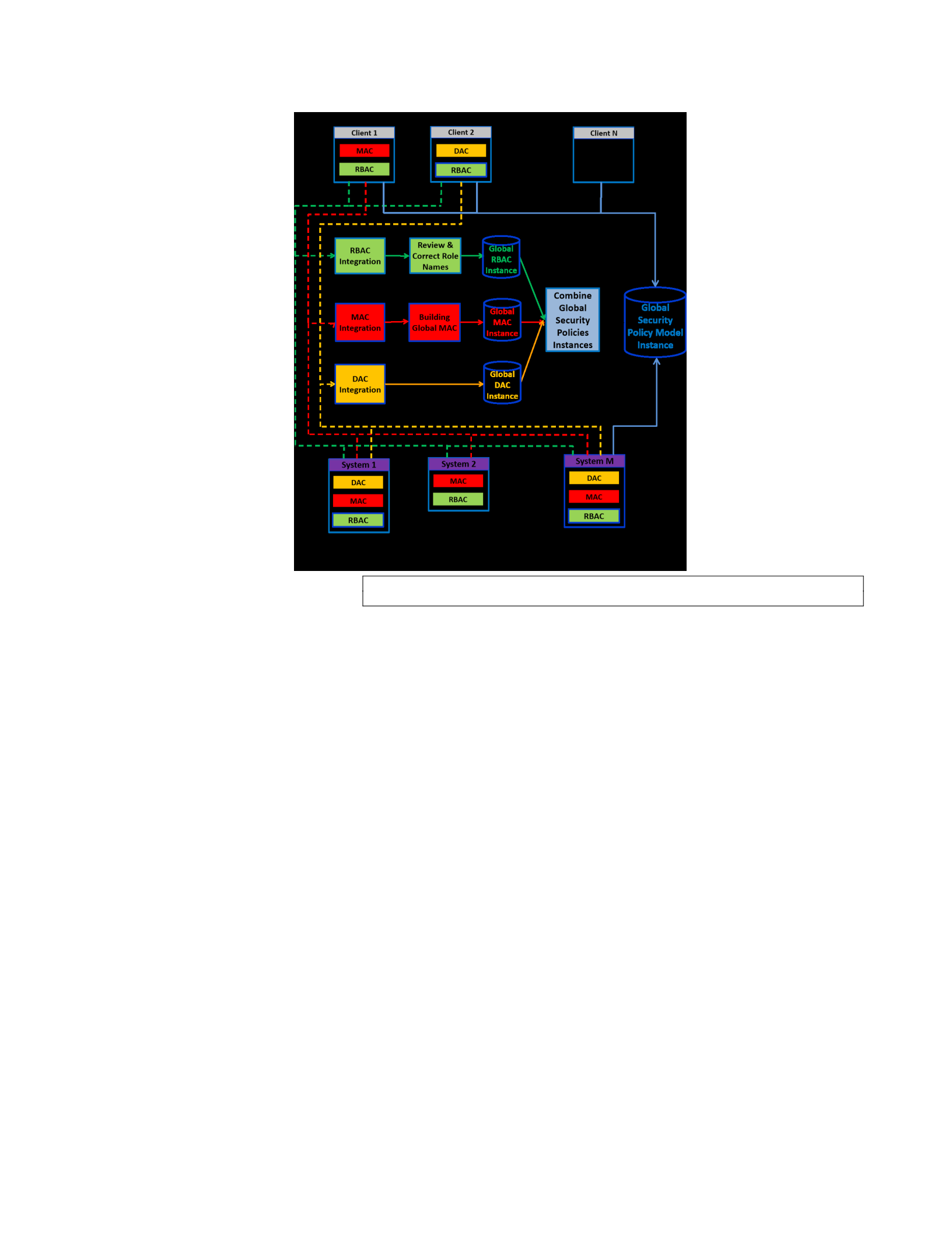
----- register security
___ utilize security
Figure 6.1. An Architecture for Global Security Policy Generation & Utilization
The remainder of this section presents and discusses a set of algorithms and human process
for the Global Security Policy Generation in four parts. In Section 6.1.1, we discuss the way that
the global RBAC generation phase processes each RBAC policy from each pure or mixed system
or mixed client, and generates the global RBAC policy. In Section 6.1.2, the global MAC
generation phase is presented to show the way that each MAC policy from each pure or mixed
system or mixed client is processed to generate the global MAC policy. Section 6.1.3 explains the
way that the global DAC generation phase uses to process each DAC policy from each pure or
mixed system or mixed client and to generate the global DAC policy. Finally, in Section 6.1.4,
we describe the way that the global policies combination phase uses the global RBAC policy,
global MAC policy, and global DAC policy to build the global security policy. Note that in the

rest of this section we use the term “system” to indicate pure systems, mixed systems (services
registering part) and mixed clients (services registering part), and the term “client” to indicate
pure clients, mixed clients (services utilization part) and mixed systems (services utilization part).
6.1.1 Global RBAC Generation
The Global RBAC (GRBAC) Generation phase is divided into two tasks, each of which
consists of one or more algorithms: RBAC Integration in Figure 6.1; and, Review and Correct
Role Names in Figure 6.1. First, the RBAC Integration task, integrates any number of systems’
RBAC policies into one global RBAC policy that can be utilized to restrict access to services of
all of the participated systems, where the presented approach makes policy integration decisions
based on permissions similarity. Since each system may define an RBAC policy against a
common set of services (the integration layer e.g., FHIR in HITs case), the similarity between
two systems’ RBAC policies, or between a system’s RBAC policy and a global RBAC policy,
can be determined based on the similarity of the permissions. For the purposes of our examples,
assume that we have two roles Srs and Grg where Srs ϵ {SRi
S ,CRi
C } is a role of a pure or mixed
system or a mixed client and Grg ϵ GRi
G is a global role. Further, assume that there are two
corresponding role permission sets Srpss ϵ { SRPSi
S ,CRPSi
C } and Grpsg ϵ GRRPSi
G . For example, say
Srs authorized to permissions Srpss ={(Patient, READ), (Patient, CREATE)}, and Grg authorized
to permissions Grpss={(Patient, READ), (Patient, CREATE), (Patient, UPDATE)}.
When comparing Srs and Grg , our focus is on comparing permissions their respective Srpss
and Grpsg ; in this case, there are common permission {(Patient, READ), (Patient, CREATE)}.
Note that, in permissions comparison, we omit the base URL from a service URI and focus only
on the Endpoint (i.e., permission name) and Method (i.e., access method), since the permission

name and access method of the service are the confidential part that need to be protected. Based
on this, the comparison between any two role permission sets (Srpss and Grpsg) have one of the
five results: (1) Srpss ⊃ Grpsg which means all of the permissions in Grpsg are in Srpss which in
the above example is false; (2) Grpsg ⊃ Srpss which means all of the permissions in Srpss are in
Grpsg which in the above example is true; (3) Srpss ∩ Grpsg ≠ ∅ (or Srpss and Grpsg overlap)
which means both role permission sets have common permissions but no role permission set
contains the other; (4) Srpss = Grpsg (or Srpss and Grpsg are equivalent) which means both role
permission sets have the same set of permissions; or (5) Srpss ∩ Grpsg = ∅ (Srpss and Grpsg are
not related) which means there is no common permissions between Srpss and Grpsg. Based on the
assumptions above, the RBAC Integration task utilizes four algorithms: Global-RBAC,
Initialize_GRBAC, IntegrateRBAC, and AddBasicParents. These algorithms utilize a set of
primitive functions in Table 6.1 that simplify the explanation of the aforementioned four
algorithms. Table 6.1 has two columns: Function Signature, that has a name and a set of
parameters for each function; and Description, that briefly explains each function. We highlight
key functions. The first three functions: returns the parent roles of a given role, sets a parent role,
and returns permissions of a role (i.e., Srpss or Grpsg). The next function, compareRolesPerm,
does the comparison between a system role (Srs) and a global role (Grg) using two factors of each
role: role permission sets (Srpss and Grpsg), and inherited role permission sets from all of the
parent roles (inhSrpss and inhGrpsg). The mapRoles function creates new entries in the global
policy regarding the mapping of system roles to global roles.
Table 6.1. Primitive Functions Utilized by the Algorithms for Global RBAC Generation
Function signature Description
getParents(RH, r) Returns all of the parent roles of the role r according to the given role hierarchy RH
addParent(RH, pr , r) Defines the role pr as a parent role of the role r in the given role hierarchy RH
dirPset(r) Returns a list of permissions directly authorized to the role r

compareRolesPerm(Grpsg ,
Srpss , inhGrpsg , inhSrpss)
Returns one of the following:
-not related (if simCount(Grpsg , Srpss) is 0)
-equivalent (if simCount(Grpsg , Srpss) equals both Grpsg.size & Srpss.size and
simCount(inhGrpsg, inhSrpss) equals both inhGrpsg.size & inhSrpss.size)
-contains GR (if simCount(Grpsg , Srpss) equals Grpsg.size but less than Srpss.size
and inhGrpsg.size is 0)
-GR contains (if simCount(Grpsg , Srpss) equals Srpss.size but less than Grpsg.size
and inhSrpss.size is 0)
-overlap (if simCount(Grpsg , Srpss) is less than both Grpsg.size & Srpss.size but > 0
or simCount(Grpsg , Srpss) equals both Grpsg.size and Srpss.size and both inhGrpsg.size
and inhSrpss.size > 0)
mapRoles(Grg, Srs) Adds all of the users in users(Srs) into users(Grg), and adds a new
entry (Grg, Srs , Srs.system name) to the role mapping list
users(r) Returns all of the users assigned to role r
createGlobalRole(roleName) Creates a new global role s.t. the role name = roleName; if roleName exists use roleName_X
(where X= number of Roles with same name +1)
comPset(r1, r2) Returns a list of common permissions between Pset(r1) and Pset(r2)
uncomPset(r1, r2) Returns a list of permissions exist in Pset(r1) but not in Pset(r2)
removePer(perList , r) Removes all of the permissions in perList from Pset(r)
addPer(perList , r) Adds all of the permissions in perList into Pset(r)
getMappedGRole(global RH,
Srs)
Returns the global role associated with the given system role Srs
AllPset(r) Returns a list of all of the permissions (directly and by inheritance) authorized to the role r
inherPset(RH, r) Returns a list of by inheritance permissions authorized to the role r according to the given role
hierarchy RH
exist(Srs) Returns true if the role mapping list contains the entry (*, Srs , Srs.system name), where *
means for any Grg
notRelatedList.add(Grg , Srs) Add an entry (Grg , Srs) that means these two roles are unrelated
notRelatedList.cleare () Removes all of the Entries
The Global-RBAC algorithm in Figure 6.2 is for generating the entire GRBAC policy for all
of the systems in FSICC, and takes as input a set of m systems’ RBAC policies (SRBAC1,
SRBAC2, .. SRBACm), where m is the number of the participated systems, and initializes the
global RBAC policy (GRBAC) using SRBAC1, line 1 in Figure 6.2. Note that, SRBAC1 is
arbitrarily chosen from the set of systems RBAC policies. The Global-RBAC algorithm then
iterates (lines 2-3) through RBAC policies of the remaining systems, SRBAC2 to SRBACm, by
integrating one system’s RBAC policy at a time with the previously computed GRBAC. Finally,
the GlobalRBAC algorithm returns the final GRBAC, combined Global RBAC policy

constructed from all of the constituent systems of FSICC, line 4 in Figure 6.2. Moreover, as
Figure 6.2 shows, the Global-RBAC algorithm utilizes the Initialize_GRBAC and IntegrateRBAC
algorithms.
Input: set of m Systems RBAC (SRBAC, SRBAC, .. , SRBACm)
Output: Global RBAC (GRBAC)
1. GRBAC ← Initialize_GRBAC(SRBAC1)
2. for i ← 2 to m
3. GRBAC ← IntegrateRBAC(GRBAC , SRBACi)
4. return(GRBAC)
Figure 6.2. The Global-RBAC Algorithm
The Initialize_GRBAC algorithm in Figure 6.3 is for initializing the GRBAC policy to
generate the initial state of a global-system role mapping list, and receives SRBAC1 and performs
three main steps. Step 1 (line 1) copies roles (Srs), users (Sus), permissions (Sscs), role-
permission authorizations (Srpss), user-role assignments (Surass), and role hierarchy (Srhs), see
Defn. 19 of Section 4., from SRBAC1 to the GRBAC. Step 2 (lines 2-3) generates a global-
system role mapping list by mapping each global role with the original system role. Step 3 (lines
4-6) creates a new global role that has no permissions or users (i.e., RootRole) to be the parent
role for each global role with no parents. Finally, the initialized GRBAC is returned in line 7.
Initialize_GRBAC
Input: System RBAC (SRBAC)
Output: Global RBAC (GRBAC)
6. addParent(global RH , RootRole , Grg)
7. return(GRBAC )
Global -RBAC

Figure 6.3. The Initialize_GRBAC Algorithm
The IntegrateRBAC algorithm in Figure 6.4 is for combining the current GRBAC policy with
a new system’s RBAC (SRBAC) policy, and receives SRBAC and the current GRBAC and
performs two nested loops. The first loop in line 1 iterates through each system role (Srs) in
SRBAC, starting with each Srs with no parents, then with one parent, and so on, until each Srs
reaches the bottom of the system role hierarchy. The second loop in line 4 iterates through each
global role (Grg) in GRBAC, except the RootRole, starting with each Grg that only has the
RootRole as its parent, then with one parent other than the RootRole, and so on, until each Grg
reaches the bottom of the global role hierarchy. Then, in line 7, each Srs and Grg are compared
based on two factors of each role: role permission sets (Srpss and Grpsg), and inherited role
permission sets from all of the parent roles (inhSrpss and inhGrpsg), utilizing the
compareRolesPerm primitive function in Table 6.1 that returns: equivalent, Grpsg Srpss, Srpss
Grpsg, overlap, or not related as explained by the compareRolesPerm function in Table 6.1. Note
that simCount, which is utilized in the description of the compareRolesPerm function in Table
6.1, is the similarity counter that is initiated to 0 and is incremented each time a global
permission and system permission are equal. There are five comparison possibilities:
•If the comparison result is “equivalent”, one step is performed: mapping Grg with Srs,
lines 8-9 in Figure 6.4.
•If the comparison result is “Grpsg Srpss”, six steps are performed: creating a new
global role (Grg_New); the common permissions between Grpsg and Srpss are removed
from Grg and added to Grg_New; adding Grg_New as a parent of Grg; adding one or

more parents to Grg_New utilizing the AddBasicParents algorithm in Figure 6.5; and,
mapping Grg_New with Srs, lines 10-16 in Figure 6.4.
Input: System RBAC (SRBAC) & current Global RBAC (GRBAC)
Output: Global RBAC (GRBAC)
1. for each Srs ∈ SRBAC
2. Srpss ← dirPset(Srs)
3. inhSrpss ← inherPset(system RH, Srs)
4. for each Grg ∈ GRBAC except RootRole
5. Grpsg ← dirPset(Grg)
6. inhGrpsg ← inherPset(global RH, Grg)
7. res ← compareRolesPerm(Grpss , Srpss, inhGrpsg, inhSrpss)
8. If(res==equivalent)
9. mapRoles(Grg, Srs)
10. Else If(res== Grpsg ⊃ Srpss)
11. Grg_new= createGlobalRole(Srs.name)
12. removePer(comPset(Grg, Srs) , Grg)
13. addPer(comPset(Grg, Srs) , Grg_new)
14. addParent(global RH , Grg_new , Grg)
15. AddBasicParents(Srs , Grg_new)
16. mapRoles(Grg_new, Srs)
17. Else If(res== Srpss ⊃ Grpsg)
18. If(!exist(Srs))
19. Grg_new= createGlobalRole(Srs.name)
20. addPer(uncomPset(Srs, Grg) , Grg_new)
21. removePer(comPset(Grg, Srs) , Srs)
22. addParent(global RH , Grg , Grg_new)
23. AddBasicParents(Srs , Grg_new)
24. mapRoles(Grg_new, Srs)
25. Else
26. removePer(comPset(Grg, Srs) , Grg_new)
27. removePer(comPset(Grg, Srs) , Srs)
28. addParent(global RH , Grg , Grg_new)
29. Else If(res==overlap)
30. Grg_new_2= createGlobalRole(NEW_ROLE)
31. addPer(comPset(Grg, Srs) , Grg_new_2)
32. removePer(comPset(Grg, Srs) , Grg)
33. addParent(global RH , Grg_new_2 , Grg)
34. addParent(global RH , RootRole , Grg_new_2)
35. If(!exist(Srs))
36. Grg_new= createGlobalRole(Srs.name)
37. addPer(uncomPset(Srs, Grg) , Grg_new)
38. removePer(comPset(Grg, Srs) , Srs)
39. addParent(global RH , Grg_new_2 , Grg_new)
40. AddBasicParents(Srs , Grg_new)
41. mapRoles(Grg_new, Srs)
42. Else
43. removePer(comPset(Grg, Srs) , Grg_new)
44. removePer(comPset(Grg, Srs) , Srs)
IntegrateRBAC

45. addParent(global RH , Grg_new_2 , Grg_new)
46. Else If(res==not related)
47. notRelatedList.add(Grg , Srs)
48. If(Srs is not related to any Grg)
49. Grg_new = createGlobalRole(Srs.name)
50. addPer(Pset(Srs) , Grg_new)
51. AddBasicParents(Srs , Grg_new)
52. mapRoles(Grg_new, Srs)
53. return(GRBAC)
Figure 6.4. The IntegrateRBAC Algorithm
•If the comparison result is “Srpss Grpsg”, there are two cases. In the first case, Srs is
not already added to the global role hierarchy, so six steps are performed: creating a
new global role (Grg_New); the common permissions between Grpsg and Srpss are
removed from Srs; the uncommon permissions between Grpsg and Srpss are added to
Grg_New; adding Grg as a parent of Grg_New; adding one or more parents to Grg_New
utilizing the AddBasicParents algorithm in Figure 6.5; and mapping Grg_New with Srs,
lines 18-24 in Figure 6.4. In the second case, Srs is already added to the global role
hierarchy, so three steps are performed: the common permissions between Grpsg and
Srpss are removed from Srs and Grg_New; and adding Grg as a parent of Grg_New, lines
25-28 in Figure 6.4.
•If the comparison result is “overlap”, the algorithm starts with five steps: creating a
new global role (Grg_New_2); the common permissions between Grpsg and Srpss are
removed from Grg and added to Grg_New_2; adding RootRole as a parent of
Grg_New_2; and adding Grg_New_2 as a parent of Grg, lines 29-34 in Figure 6.4. Then
the algorithm applies similar steps as in the “Srpss Grpsg” case, except that
Grg_New_2 (instead of Grg) is added as a parent of Grg_New, lines 35-45 in Figure 6.4.

•If the result of all of the comparisons between Srpss and all of the Grpsg is “not
related”, four steps are performed: creating a new global role (Grg_New); adding the
permission set of Srs to Grg_New; adding one or more parents to Grg_New utilizing the
AddBasicParents algorithm in Figure 6.5; and mapping Grg_New with Srs, lines 48-52
in Figure 6.4.
Finally, the IntegrateRBAC algorithm returns the resulted GRBAC, line 53 in Figure 6.4.
Moreover, the AddBasicParents algorithm in Figure 6.5, that is utilized extensively by the
IntegrateRBAC algorithm, is for adding a set of parent roles to a specific role, and receives a
system role (Srs) and a new global role (Grg_New). Then, if Srs has no parents, the RootRole is
added as a parent of Grg_New. However, if Srs has one or more parents, for each parent of Srs, the
associated Grg is retrieved and added as a parent of Grg_New. The Global-RBAC algorithm runs
in polynomial time and has a worst-case complexity of O(m|P|), where m is the number of the
participated systems and |P| is the total number of permissions from all of the systems RBAC’
policies. That is, the Global-RBAC algorithm visits each RBAC of each system once in which
each permission is compared once.
AddBasicParents
Input: a system role (Srs), and a new global role (Grg_new)
1. parentList=getParents(system RH, Srs)
2. If(parentList==Null)
3. addParent(global RH , RootRole , Grg_new)
4. Else
5. for each prnt parentList
6. gPrnt=getMappedGRole(global RH, prnt) 7. addParent(global RH , gPrnt,
Grg_new)
Figure 6.5. The AddBasicParents Algorithm

The second task of the global RBAC generation phase is Review and Correct Role Names.
The main purpose of this task is to address two issues that the generated global RBAC policy
may have as a result of using the algorithms in Figures 6.2 to 6.5. Issue 1 can arise when a
system role and global role comparison is “overlap” can the automatically created new role name
is not real. Issue 2 can arise when two different Global roles are generated with very similar
names but with dramatically different permissions. Specifically, when the IntegrateRBAC
algorithm compares each global role Grg to each system role Srs, in which the comparison result
is “overlap”, a new global role named “NEW_ROLE” is created, clearly this is not a real role
name (issue 1).
Moreover, when the IntegrateRBAC algorithm processes all of the comparison cases, except the
“equivalent” case, a new global role is created in which its name is copied from a system role Srs
followed by a number X, where X is 1 plus the number of global roles that share a similar role
name with Srs. Based on this, the IntegrateRBAC algorithm may generate a GRBAC that has two
global roles that have a similar role name but are authorized to different sets of permissions; this
is not a desirable situation (issue 2). For example, assume that the GRBAC had a global role
named “Patient” that is authorized to {(Patient, READ), (Patient, CREATE)}, and the
IntegrateRBAC algorithm is about to create a new global role named “Patient” that is authorized
to {(Observation, READ), (Observation, CREATE)}. In this case, the IntegrateRBAC algorithm
will create a new global role named “Patient_2”, note that the number 2 here came from 1+
number of global roles that share a similar role name with “Patient” which is 1, and hence the
GRBAC now has two global roles: “Patient” with permissions {(Patient, READ), (Patient,
CREATE)}, and “Patient_2” with permissions {(Observation, READ), (Observation, CREATE)}.
Our approach to solve not a real role name (issue 1) and two global roles with similar role name

and radically different permissions (issue 2) is through the Review and Correct Role Names task,
which has two steps. In the first step, the security engineer of FSICC reviews and suggests a
name for each of two conflicting global roles, based on the authorized permission. The two new
roles are generated as described in issue 1 or 2 and a name list of corrected global roles in the
form of
(global role ID, corrected name) is also generated. In the second step, the security engineer of
FSICC sends the name list of corrected global roles to the Update Global Roles algorithm, as
shown in Figure 6.6. The Update Global Roles algorithm iterates through the name list of
corrected global roles and for each global role Grg_U in the list, the algorithm finds a global role
Grg in GRBAC in which the id of both entries is equal. Then, the algorithm updates the name of
the global role Grg to be the name of the corrected global role Grg_U and finally returns the
updated global RBAC policy GRBAC, see lines 1-4 of Figure 6.6.
Input: Global Roles List (GRL) & current Global RBAC (GRBAC) Output:
Global RBAC (GRBAC)
1. for each Grg_U GRL
2. find Grg GRBAC s.t. Grg.id = Grg_U.id
3. Grg.name = Grg_U.name 4. return(GRBAC)
Figure 6.6. The Update Global Roles Algorithm
6.1.2 Global MAC Generation
The Global MAC (GMAC) Generation phase is divided into two tasks in Figure 6.1: MAC
Integration and Building Global MAC. The MAC Integration task is conducted based on the
assumption that the five sensitivity levels, introduced in Section 4.4, (0-Public Information,
1Basic Sensitive Information, 2-Sensitive Information Summary, 3-Sensitive Information
Update Global Roles
∈

Details, and 4-Very Sensitive Information), are available to each system to classify their data and
to assign each user a clearance. This can be useful in a complex domain such as healthcare all of
the five levels are expected to be utilized due to the fact that healthcare data is complex, while in
other domain such as education only a subset of the five sensitivity levels may be needed to
classify data in that domain. However, although all of the participating systems are using the
same set of sensitivity levels, two systems may have different semantic and usages of each
sensitivity level. To overcome this issue, the presented sensitivity levels mapping step can be
utilized. That is, this step is a human interaction between the security engineer of FSICC and the
security engineers of participating systems to map each system sensitivity levels to the global
sensitivity levels so that one set of sensitivity levels (the global sensitivity levels) can be utilized
to: assign each service from each system a classification; and assign each user from each system
a clearance, as we explain in the second task below. Note that the semantics of the global
sensitivity levels is based on the sensitivity levels of the first participating system. The output of
this task is a sensitivity levels mapping list in which each entry in the list has the following
format {a global sensitivity level, a system sensitivity level, system name}.
Second, based on the sensitivity levels mapping list that is generated in the MAC Integration
task, in the Building Global MAC task, the global MAC, GMAC, is generated utilizing users and
services from each participating system in which users’ clearances and services’ classifications
are assigned based on the global sensitivity levels in which the read/write properties of each user
are remain unchanged. To perform this task, the security engineer of FSICC needs to send the
sensitivity levels mapping list to the global MAC algorithm, see Figure 6.7, that utilizes a set of
primitive functions in Table 6.2 to generate the global MAC policy. These primitive functions
simplify the explanation of the global MAC algorithm. Table 6.2 has two columns: Function

Signature, that has a name and a set of parameters for each function; and Description, that briefly
explains each function. The global MAC algorithm takes as input: the sensitivity levels mapping
list (SLML) and a set of m MAC policies from each participating system. The algorithm goes
through each MAC policy of each system to add users and services of that MAC policy. First, in
lines 2-6, the first loop iterates through each user of each system MAC policy to: find the global
clearance that is associated with the user system’s clearance; retrieve the read and write
properties; and, add the user into the global MAC policy as a global user. Second, in lines 7-9,
the second loop iterates through each service of each system MAC policy to: find the global
classification that is associated with the service system’s clearance; and, add the service into the
global MAC policy as a global service. Third, the algorithm returns the GMAC. The global MAC
algorithm runs in linear time and has a worst-case complexity of O(m), where m is the number of
the participated systems. That is, the global MAC algorithm visits each MAC of each system
once.
Input: set of m Systems MAC (SMAC1, SMAC2, .. , SMACm) and sensitivity
levels mapping list (SLML)
Output: Global MAC (GMAC)
1. for i ← 1 to m
2. for each user u in SMACi[Sus]
3. u.gCLR=globalClearance(SLML, u.CLR, SMACi.Name)
4. u.gRP= u.RP
5. u.gWP= u.WP
6. addUser(GMAC, u)
7. for each service s in SMACi[Sscs]
8. s.gCLS=globalClassification(SLML, s.CLS, SMACi.Name)
9. addService(GMAC, s)
10. return(GMAC)
Figure 6.7. The Global-MAC Algorithm
Global -MAC

Table 6.2. Primitive Functions Utilized by the Algorithms for Global MAC Generation
Function signature Description
globalClearance(SLML, u.CLR, SMACi.Name) Returns a global sensitivity level in SLML that is mapped to u.CLR of
the SMACi.Name system
globalClassification(SLML, s.CLS, SMACi.Name) Returns a global sensitivity level in SLML that is mapped to s.CLS of the
SMACi.Name system
addUser(GMAC, u) Adds the user u to the global MAC
addService(GMAC, s) Adds the service s to the global MAC
6.1.3 Global DAC Generation
The Global DAC (GDAC) Generation phase has one main task and one algorithm, DAC
Integration in Figure 6.1. This task takes all of the DAC policies from each system and combines
them into one global DAC policy. The DAC Integration task is performed through the global
DAC algorithm, see Figure 6.8, that utilizes a set of primitive functions in Table 6.3 to generate
the global DAC policy. These primitive functions simplify the explanation of the global DAC
algorithm. Table 6.3 has two columns: Function Signature, that has a name and a set of
parameters for each function; and Description, that briefly explains each function. The global
DAC algorithm takes as input: the global RBAC, the global MAC, and a set of m DAC policies
from each participating system. The algorithm iterates through each DAC policy of each system
to retrieve and add role and/or clearance delegations into the global DAC policy. First, in lines
24, the first loop iterates through each role delegation rd of each system DAC policy to: find the
global IDs of delegator user, delegated user, and delegated role using the getGobalIDs primitive
function in Table 6.3; and, add a new role delegation into the global DAC policy using the
retrieved global IDs. Next, in lines 5-7, the second loop iterates through each clearance
delegation cd of each system DAC policy to: find the global IDs of delegator user, delegated
user, and delegated clearance using the getGobalIDs primitive function; and, add a new clearance
delegation into the global DAC policy using the retrieved global IDs. Finally, the algorithm
returns the global DAC policy. The global DAC algorithm runs in polynomial time and has a

worst-case complexity of O(m|d|), where m is the number of the participated systems and |d| is
the total number of all of the role and clearance delegations from all of the systems DAC’s
policies.
That is, the global DAC algorithm visits each DAC of each system once.
Input: set of m Systems DAC (SDAC1, SDAC2, .. , SDACm),
GMAC, and GRBAC
Output: Global DAC (GDAC)
1. for i ← 1 to m
2. for each role delegation rd in SDACi[Sdss]
3. global_rd =getGlobalIDs(rd)
4. addGlobalDel(GDAC, global_rd)
5. for each clearance delegation cd in SDACi[Sdss]
6. global_cd =getGlobalIDs(cd)
7. addGlobalDel (GDAC, global_cd)
8. return(GDAC)
Figure 6.8. The Global-DAC Algorithm
Table 6.3. Primitive Functions Utilized by the Algorithms for Global DAC Generation
Function signature Description
getGlobalIDs(rd/cd) Returns global IDs of delegator, delegated, and role/sensitivity level
addGlobalDel(GDAC, global_rd/cd) Adds a global role/clearance delegation to global DAC
6.1.4 Global Policies Combination
The results from the algorithms in Sections 6.1.1-6.1.3 serve as input to the combine global
security policies instances phase that is divided into two tasks: combining the generated global
RBAC instance, global MAC instance, and global DAC instance into one global security policy
model instance which can be utilized by any interested clients to control their own services; and,
controlling the way that data that global services can access are read and/or writtenn. The first
task generates one policy document that concatenates all of the separate policies (i.e., GRBAC,
Global -DAC

GMAC, and GDAC) into one Global policy. The second task is intended to restrict clients at the
data level. That is, while the global RBAC, MAC and DAC policies control who can access what
set of global services, the controlling data task is intended to control what set of data, that global
services can access and what each user can read/write. To control reading data actions, there are
three read data access types that the security engineer of FSICC needs to choose from:
1. Open to All (default): This read data access type is for the case where two or more users,
from different systems, who are assigned to the same global role can read any data that
the global role can retrieve.
2. Open to Same System Users: This read data access type is for the case where a user from
system X who is assigned to a global role can only read a subset of data (only data from
system X) that the global role can retrieve.
3. Customize Data Read: This read data access type is for the case in which for each global
service, the security engineer of FSICC needs to specify which systems that their users
can read the retrieved data.
Moreover, to control writing data actions, there is one write data access type:
1. Open to Same System Users: This write data access type is for the case where a user from
system X who is assigned to a global role can only write data (only data from system X)
that the global role can write.
The output of the global policies combination step is a single unified security policy document
that has global RBAC, global MAC, and global DAC coupled with one read data access type and
one write data access type.

6.2 HAPI FHIR Implementation and RBAC/MAC/DAC Interceptors
In this section, we demonstrate the realization of UCCACM of FSICC via a HAPI FHIR
Implementation and the underlying RBAC/MAC/DAC Interceptors. These are represented by the
Security Enforcement via the Interceptors box of the GSP and GAPI Utilization and the Security
Enforcement horizontal box in Figure 1.3 from Chapter 1, utilizing the healthcare scenario of
Section 2.4 of Chapter 2. This leads to that the implementation of HAPI FHIR APIs and its server
interceptor to support UCCACM checks with three different algorithms to support three different
HAPI FHIR interceptors: RBAC interceptor, MAC interceptor, and DAC interceptor. This
section involves the implementation of FHIR APIs and the customization and adaptation of the
HAPI server interceptor to support UCCACM checks: Defns. 50 and 51 that determine if a
service is authorized by a user/role pair; Defn. 55 that determines if a service is authorized by a
user/clearance pair; and Defns. 57, 58, and 59 that determine if a service is authorized by a
user/(delegated_role/delegated_service /delegated_clearance) pair (see Section 4.7). Three
integration layers were implemented utilizing the HAPI FHIR reference library (HAPI
community, 2016), namely: Clients, top of Figure 1.1 and Involved Parties component of Figure
1.2; Systems, bottom of Figure 1.1 and Involved Parties component of Figure 1.2; and FSICC,
the Global Services in the middle of Figure 1.1.
The remainder of this section has five subsections. Section 6.2.1 provides a more detailed
discussion than Section 2.3 of Chapter 2 on HAPI-FHIR Concepts and Background. Using this
as a basis, Sections 6.2.2, 6.2.3, and 6.2.4 review and explain, respectively, the RBAC
interceptor, MAC interceptor, and DAC interceptor. Finally, Section 6.2.5 presents two usage
scenarios utilizing the global security policy sample from Sections 6.2.2, 6.2.3, and 6.2.4.

6.2.1 HAPI-FHIR Concepts and Background
As discussed in Section 2.3, the HAPI-FHIR library provides a general HAPI server
interceptor (University Health Network, 2016) which is a programmatic approach that allows a
developer to examine each incoming HTTP request to add useful features to the HAPI
ResfulServer such as authentication, authorization, auditing, logging, etc. This is accomplished
by implementing a number of methods: incomingRequestPreProcessed that is invoked before
performing any action to the request; incomingRequestPostProcessed that is invoked after
determining the request type by classifying the request; incomingRequestPreHandled which is
invoked before sending the request to the Resource Provider; and, outgoingResponse which is
invoked after the request is handled by the appropriate Resource Provider. To implement each of
these HAPI FHIR APIs, the HAPI RestfulServer and HAPI IResourceProvider classes were
utilized.
To support cloud computing capability 3 (Global Registration, Authentication, Authorization,
and Service Discover for Consumers) of FSICC (see Section 3.2), the Clients Registry, Systems
Registry, and Global Security Policy components in Figure 1.1 are developed as simple RESTful
APIs, which were implemented using the JAX-RS Java library (Hadley & Sandoz, 2009). The
Clients Registry and Systems Registry components supports adding systems/clients HAPI-FHIR
APIs and discovering corresponding FHIR APIs, while the Global Security Policy component
enables the security engineer of FSICC to add/modify the global policy in Section 4.6 of Chapter
4 (see Defn. 39 of UCCACM). In addition, the RBAC, MAC, and DAC interceptors presented in
Section 4.7 of Chapter 4 (see Defns. 52, 56, and 60 of UCCACM respectively - middle of Figure

1.1), were implemented by extending the HAPI InterceptorAdapter class to retrieve the global
security policy from the Global Security Policy component and then extract the appropriate part
(i.e., global RBAC for the RBAC Interceptor, global MAC for the MAC Interceptor, and global
DAC for the DAC Interceptor) in order to performing enforcement check on each access request
at runtime. Although each of the RBAC interceptor, MAC interceptor, and DAC interceptor is
designed to enforce the appropriate global security policy separately, the handleRequest method
of the RestfulServer class works as a monitor that makes sure each part of the global security
policy (RBAC, MAC, and DAC) is checked and enforced, via the three interceptors, before
allowing any access request.
6.2.2 RBAC Interceptor
To support security requirement 2 of FSICC, Control Access to Cloud Services Using RBAC,
in this section, we present and explain the pseudo-code of the RBAC interceptor (see Defn. 52 of
UCCACM) that is utilized at runtime to check security permissions (see Defns. 50 and 51 of
UCCACM) of all of the calls to global services. To facilitate our explanation on the RBAC
interceptor, Figure 6.9 presents a global RBAC policy example in JSON format that consists of:
USERS, ROLES, RESOURCES, USER_ROLE_ASSIGNMENTS,
ROLE_RESOURCE_AUTHORIZATIONS, ROLE_HIERARCHY, & ROLES_MAPPINGS.
Each user is represented by three fields: id, name, and system_name. Each role is represented by
two fields: id and name. Each resource is represented by three fields: id, name, and method. Each
user_role_assignment is represented by two fields: user_id and role_id. Each
role_resource_authorization is represented by two fields: role_id and resource_id. Each
role_hierarchy relationship is represented by two fields: role_id and parent_id. Finally, each
role_mapping is represented by three fields: global_role_id, system_role_id, and system_name.

As shown in Figure 6.9, the global SECURITY_POLICY is based on the healthcare scenario
example from Section 2.4 of Chapter 2. Notice that there are users, Defn. 14, defined for the
systems OpenEMR and MyGoogle and the client app SMH. Likewise, there are roles, Defn. 8,
that include roles from OpenEMR and MyGoogle systems, roles form the SMH client app, and
new roles generated as during combining roles of OpenEMR and MyGoogle systems, and SMH
client app. The Global RBAC example, Figure 6.9, also has a set of resources, Defn. 2, that are
created from OpenEMR and MyGoogle systems, and SMH client app. The user role assignment
set, Defn. 16, in the Global RBAC example is generated based on user role assignment sets from
OpenEMR and MyGoogle systems, and SMH client app. Similarly, the role resource
authorization set, Defn. 13, in the Global RBAC example is compiled based on role resource
authorization sets from OpenEMR and MyGoogle systems, and SMH client app. The role
hierarchy, Defn. 19, in the figure describes how roles in the Global RBAC example relate to each
other using the parent-child relationship. Finally, the role mapping, Defn. 45, in the figure shows
how each role in the Global RBAC example is mapped to the original role in OpenEMR or
MyGoogle systems, or SMH client app.
In the Global RBAC example, 5 different global users are shown, three from systems (John,
Sara, ShareMyHealth) and two from clients (Sarah and Nasser). There have been 11 global roles
created, that have different origins: Physician with role id 1 was an original role of OpenEMR,
Patient_2 with role id 4 was an original role of CT2, and RootRole with role id 3 was created as a
parent role for all of the root roles from each system and client. Note that a root role in a system
or client is the role that has no parents but has at least one child. The Global RBAC example also
has 5 global resources: Observation with resource id 1 and GET method name; Patient with
resource id 2 and PUT method name; Observation with resource id 3 and PUT method name;

Patient with resource id 4 and GET method name; and Person with resource id 5 and PUT
method name. Each user is assigned a role based on their ids. For example, the user with id 1 is
assigned the role with id 1, the user with id 3 is assigned the role with id 4, and the user with id 5
is assigned the role with id 10. Likewise, some roles are authorized to access some resources
based on their id. For example, the role with id 6 is authorized to access the resource with id 1,
the role with id 8 is authorized to access the resource with id 2, and the role with id 11 is
authorized to access the resource with id 5. Based on the role hierarchy presented in Figure 6.9:
the role with id 3 is a parent of roles with id 6, 7, 8, 9 and 11; the role with id 9 is a parent of
roles with id 2, 4, and 10; and, the role with id 11 is a parent of roles with id 4, and 10. Finally,
the role mapping in the Figure 6.9 shows that: the global role with id 1 is originated from the
OpenEMR’s system role with id 1; the global role with id 4 is originated from the SMH’s client
role with id 1; and, the global role with id 10 is originated from the MyGoogle’s system role with
id 1.
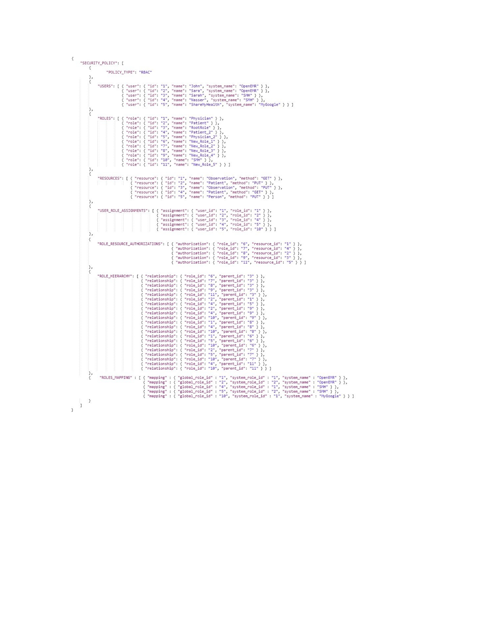
Figure 6.9. A Global RBAC Policy Example in JSON
Figure 6.10 presents the RBAC enforcement code realized within the
incomingRequestPostProcessed method of the RBAC Interceptor as introduced in Section 6.2.1,
which is an extension of the HAPI InterceptorAdapter class, which is registered in the
RestfulServer class. This method starts by retrieving a secure Token (line 3) from a HTTP header
(Authorization) of the request parameter, that is then passed to the extractUser function that can

obtain the user credentials (user Id, see Defn. 15v2, and role Id, Defn. 9v2) from the Token (line
5). Next, the Global Policy (see Defn. 39), which is in JSON format, is retrieved by calling the
Global Policy URL (line 7). The global RBAC policy example in Figure 6.9, is then extracted
from the Global Policy through the extract_RBAC function (line 8). Then, the details of the
requested resource (resource name, see Defn. 2, and HTTP method, see Defn. 4) are obtained
from the requestDetails and request parameters, respectively, and passed along with the RBAC
policy to the getResourceId function that returns the Id of the requested resource (lines 9 to 11).
In line 14, the user credentials and the RBAC policy are passed to the checkCredentials function
(see Defn. 50) to determine whether the user has the claimed role (see Defn. 9v2). If the check
fails, the value of the accessDecision variable becomes false (lines 27-30). If the user passes the
check, the associated role Id, the resource Id, and the RBAC policy are passed to the checkPerm
function (see Defn. 51 - line 19) that returns true if the user with such a role can access the
requested resource or false otherwise. Note that the checkPerm function works by retrieving a list
of parent roles of the user role (passed) based on the global role hierarchy, part of RBAC policy,
in which the user can access all of the resources that are authorized to the user role of any of its
parents. Based on the result of the checkPerm function, the variable accessDecision is assigned
(true or false) and returned as the result of the incomingRequestPostProcessed method
(lines 20-25 and 31).

1 //Serves as Access Control Interceptor function
2 public boolean incomingRequestPostProcessed(requestDetails, request, response){
3 secToken = request.getHeader(“Authorization”);
4 // Retrieves the user id and role id of the current user
5 [userId,roleId] = extractUser(secToken);
6 // Retrieves the RBAC policy from the Global Policy URL
7 Global_Policy= HttpGet(Global_Policy_URL);
8 RBAC_Policy= extract_RBAC(Global_Policy);
9 resourceName = requestDetails.getResourceName();
10 httpMethod = request.getMethod();
11 resourceId = getResourceId(httpMethod, resourceName, RBAC_Policy);
12 // check if the user has the claimed role
13 verifiedUser=false;
14 verifiedUser=checkCredintals(userId, roleId, RBAC_Policy); // true or false 15 //
check if the user (role) can access the requested resource and method
16 verifiedPerm=false;
17 accessDecision=false;
18 if(verifiedUser==true){
19 verifiedPerm=checkPerm(roleId, resourceId, RBAC_Policy); // true or false 20
if(verifiedPerm==true){
21 accessDecision=true; // allow user request
22 }
23 else {
24 accessDecision=false; // deny user request
25 }
26 }
27 else{
28 // Error Message: User could not be verified
29 accessDecision=false; // deny user request
30 }
31 Return accessDecision;
32 }
Figure 6.10. RBAC Interceptor Pseudo Code.
6.2.3 MAC Interceptor
To support security requirement 4 of FSICC, Control Access to Cloud Services Using MAC,
in this section we present and explain the pseudo-code of the MAC interceptor (see Defn. 56 of
UCCACM) that is utilized at runtime to check security permissions (see Defn. 55 of UCCACM)
of all of the calls to global services. To facilitate our explanation, Figure 6.11 presents a global
MAC policy example in JSON format that consists of three parts: USERS, RESOURCES, and
SENSITIVITY_LEVELS_MAPPING_LIST. Each user is represented by six fields: id, name,
clearance, read property, write property, and system_name. Each resource is represented by four
fields: id, name, method, and classification. Finally, each sensitivity level mapping is represented
by four fields: id, global_level, system_level, and system_name. Notice that there are users,
Defn. 10, defined for the systems OpenEMR and MyGoogle and the client app SMH. The Global
MAC example, Figure 6.11, also has a set of resources, Defn. 2, that are created from OpenEMR

and MyGoogle systems, and SMH client app. Finally, the sensitivity levels, Defn. 10, mapping
list in the figure shows how each sensitivity level in the Global MAC example is mapped to the
original sensitivity level in OpenEMR or MyGoogle systems, or SMH client app.
In the Global MAC example, 5 different global users are shown, three from systems (John,
Sara, ShareMyHealth) and two from clients (Sarah and Nasser). Moreover, the user John has:
level 3 or Sensitive Information Details clearance; SS read property; and SI write property. The
user Sara has level 2 or Sensitive Information Summary clearance; SS read property; and SI write
property. The user Sarah has level 4 or Very Sensitive Information clearance; SS read property;
and SI write property. In addition, each of users Nasser and ShareMyHealth has level 3 or
Sensitive Information Details clearance; SS read property; and L* write property. There are 5
global resources: Observation with resource id 1 and GET method name; Patient with resource id
2 and PUT method name; Observation with resource id 3 and PUT method name; Patient with
resource id 4 and GET method name; and Person with resource id 5 and PUT method name. Note
that all resources have level 1 or Basic Sensitive Information clearance. Finally, the sensitivity
levels mapping list in the Figure 6.11 shows that: global level 0 (Public Information) is mapped
to level 0 (Public Information) of OpenEMR; SMH; and MyGoogle. Global level 3
(Sensitive Information Details) is mapped to: level 3 (Sensitive Information Details) of
OpenEMR; level 2 (Sensitive Information Summary) of SMH and level 4 (Very Sensitive
Information) of MyGoogle. Global level 4 (Very Sensitive Information) is mapped to level 4
(Very Sensitive Information) of OpenEMR and SMH but is not mapped to any level of
MyGoogle.
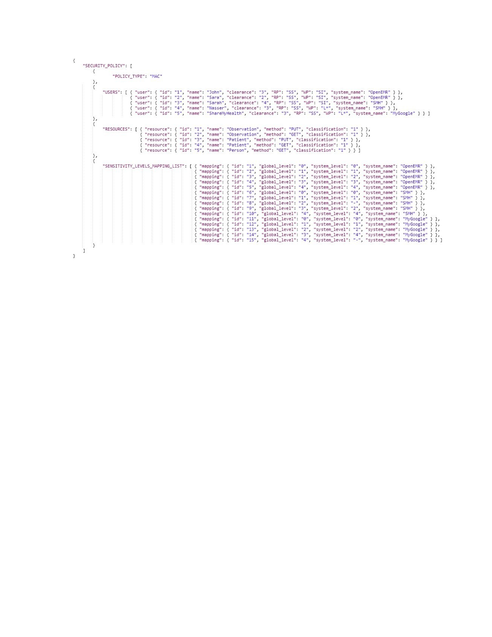
Figure 6.11. A Global MAC Policy Example in JSON
Figure 6.12 has the MAC enforcement code realized within the
incomingRequestPostProcessed method of the MAC Interceptor, which is an extension of the
HAPI InterceptorAdapter class, which is registered in the RestfulServer class. This method starts
by retrieving a secure Token (line 3) from a HTTP header (Authorization) of the request
parameter, that is passed to the extractUser function that can obtain the user credentials (user Id,
see Defn. 15v3) from the Token (line 5). Then, the Global Policy (see Defn. 39), which is in the
JSON format, is retrieved by calling the Global Policy URL (line 7). The MAC policy, see the
global MAC policy example in Figure 6.11, is then extracted from the Global Policy through the
extract_MAC function (line 8). Next, in line 10, the user Id and MAC policy are passed to the
getUserDetails function that returns the user details (i.e., user clearance, Read property, and
Write property). Then, the details of the requested resource (resource name, see Defn. 2, and
HTTP method, see Defn. 4) are obtained from the requestDetails and request parameters,
respectively, and passes along with the MAC policy to the getResourceId function that returns the

Id of the requested resource (lines 11 to 13). In line 15, the resource Id and MAC policy are
passed to the getResourceCLS function to find the resource classification level. Then, using the
user details and the requested resource details, the accessDecision variable is set to true, if the
user clearance satisfies the user’s predefined read or write properties on the requested resource
and method, or false, otherwise (lines 17 to 41). Finally, in line 42, the value of the
accessDecision variable is returned as the result of the incomingRequestPostProcessed method.
1 //Serves as Access Control Interceptor function
2 public boolean incomingRequestPostProcessed(requestDetails, request, response){
3 secToken = request.getHeader(“Authorization”);
4 // Retrieves the user id of the current user
5 userId = extractUser(secToken);
6 // Retrieves the MAC policy from the Global Policy URL
7 Global_Policy= HttpGet(Global_Policy_URL);
8 MAC_Policy= extract_MAC(Global_Policy);
9 // Retrieves the Clearance level, Read, and Write properties of the current user
10 [UserCLR, RP, WP] = getUserDetails(userId , MAC_Policy);
11 resourceName = requestDetails.getResourceName();
12 httpMethod = request.getMethod();
13 resourceId = getResourceId(httpMethod, resourceName, MAC_Policy);
14 // Retrieves the classification level of the requested resource
15 ResourceCLS = getResourceCLS(resourceId , MAC_Policy);
16 // check if user with a CLR, Read, & Write properties can access requested resource and method
17 accessDecision=false;
18 if(httpMethod==“GET”){
19 if(RP==“SS”){
20 if(UserCLR < ResourceCLS ){ accessDecision=false; }
21 else{ accessDecision=true; }
22 }
23 else if(RP==“SSR”) {
24 if(UserCLR != ResourceCLS ){ accessDecision=false; }
25 else{ accessDecision=true; }
26 }
27 }
28 elseif(httpMethod==“POST” || httpMethod==“PUT” || httpMethod==“DELETE”){
29 if(RP==“SI”){
30 if(UserCLR < ResourceCLS ){ accessDecision=false; }
31 else{ accessDecision=true; }
32 }
33 else if(RP==“LS”) {
34 if(UserCLR > ResourceCLS ){ accessDecision=false; }
35 else{ accessDecision=true; }
36 }
37 else if(RP==“SSW”) {
38 if(UserCLR != ResourceCLS ){ accessDecision=false; }
39 else{ accessDecision=true; }
40 }
41 }
42 Return accessDecision;
43 }
Figure 6.12. MAC Interceptor Pseudo Code.
6.2.4 DAC Interceptor
To support security requirement 3 of FSICC, Support Delegation of Cloud Services Using
DAC, in this section, we present and explain the pseudo-code of the DAC interceptor (see Defn.
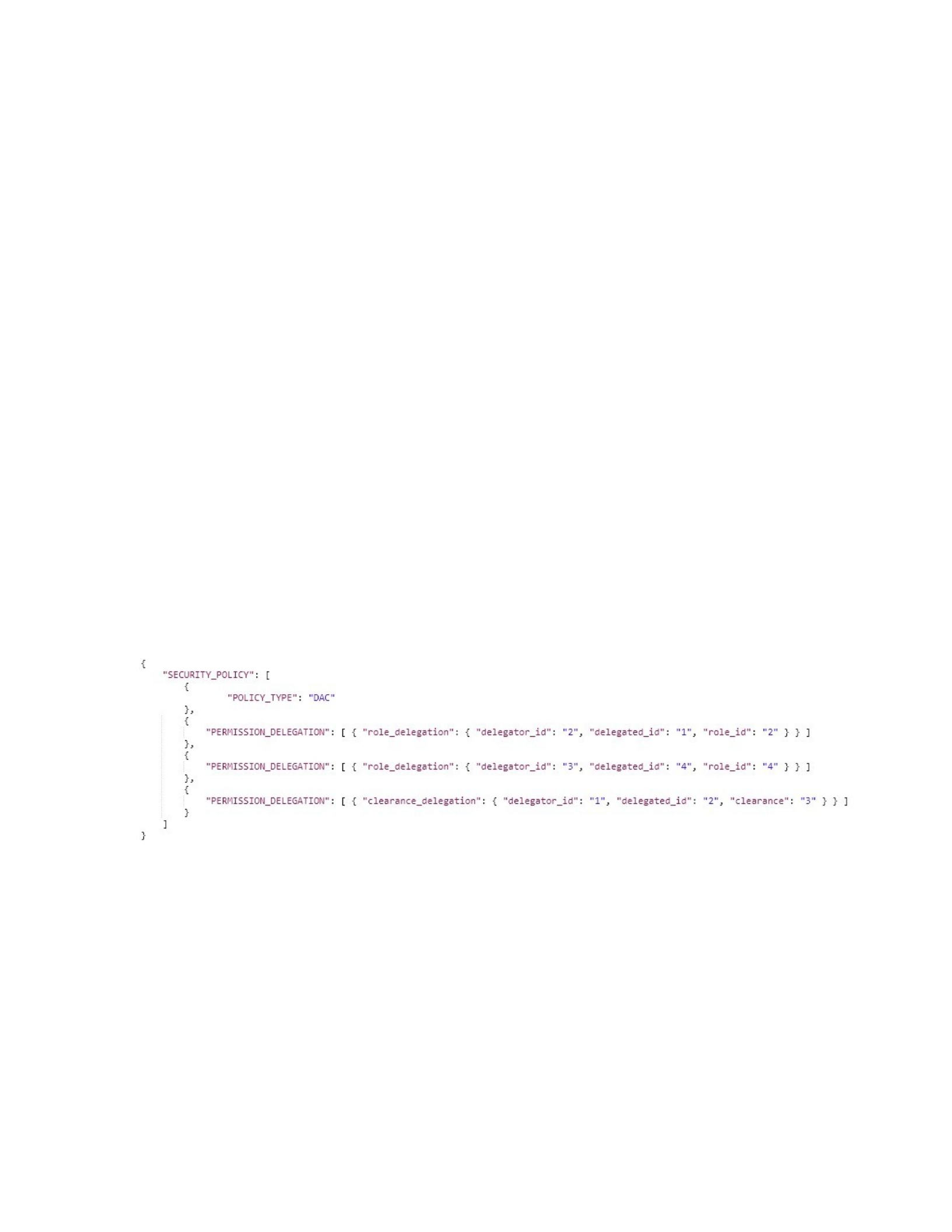
60 of UCCACM) that is utilized at runtime to check security permissions (see Defns. 57, 58, and
59 of UCCACM) of all of the calls to global services. To facilitate the explanation, Figure 6.13
presents a global DAC policy example in JSON format that consists of one main part,
PERMISSION_DELEGATION, that can have role delegation, or clearance delegation. Each role
delegation is represented by three fields: delegator_id, delegated_id, and role_id. Each clearance
delegation is represented by three fields: delegator_id, delegated_id, and clearance. Notice that
the role delegation set, Defn. 25, in Figure 6.13 is based on a set of role delegations from
OpenEMR and MyGoogle systems, and SMH client app. Likewise, the clearance delegation set,
Defn. 24, in the figure is based on a set of clearance delegations from OpenEMR and MyGoogle
systems, and SMH client app. For example, the first permission delegation in the Global DAC
example, is a role delegation in which the user with id 2, see Figure 6.9, passed on the
authorization of the role (Patient) with id 2 to the user with id 1.
Figure 6.13. A Global DAC Policy Example in JSON
Figure 6.14 has the DAC enforcement code realized within the
incomingRequestPostProcessed method of the DAC Interceptor, which is an extension of the
HAPI InterceptorAdapter class, which is registered in the RestfulServer class. Basically, the
DAC enforcement code is a combination of both the RBAC enforcement code, lines 3-11 and
line 19, and the MAC enforcement code, lines 21-22, 24-25, and 27-50, with role delegation and

clearance delegation checks. This method starts by retrieving a secure Token from a HTTP
header (Authorization) of the request parameter, that is passed to the extractUser function that
can obtain the user credentials (i.e., user Id, see Defn. 15v2, and role Id, see Defn. 9v2) from the
Token (line 4). Then, the Global Policy (see Defn. 39), which is in JSON format, is retrieved by
calling the Global Policy URL (line 5). The global RBAC policy example in Figure 6.9 is then
extracted from the Global Policy through the extract_RBAC function (line 6). Next, the details of
the requested resource (resource name, see Defn. 2, and HTTP method, see Defn. 4) are obtained
from the requestDetails and request parameters, respectively, and are passed along with the
RBAC policy to the getResourceId function that returns the Id of the requested resource (lines 7
to 9). In line 11, the user credentials and the RBAC policy are passed to the checkCredentials
function (see Defn. 50) to determine whether the user has the claimed role (see Defn. 9v2). Then,
the global DAC policy example in Figure 6.13 is extracted from the Global Policy through the
extract_DAC function (line 12). If the checkCredentials check fails, another check (lines 13-15)
is performed to determine whether such a role is delegated to the current user by another user.
This is done by passing the user Id, the claimed role Id, and the DAC policy to the
checkRoleDelegation function that returns true if the entry delegated_id(user Id)/claimed role
exists or false otherwise to the verifiedRoleDelegation variable.
If both checks fail (line 18), the value of the accessDecision variable becomes false (lines
5759). However, if the user passed at least one of these checks, the associated role Id, the
resource Id, and the RBAC policy are passed to the checkPerm function (see Defn. 51 - line 19)
that returns true if the user with such role (or delegated role) can access the requested resource or
false otherwise. Note that the checkPerm function first retrieves a list of parent roles of the user
role (passed) based on the global role hierarchy, part of RBAC policy, in which the user can

access all of the resources that are authorized to the user role of any of its parents. If the
checkPerm function returns false, then the variable accessDecision is set to false (lines 53-54).
However, if the checkPerm function returns true, then the global MAC policy example in Figure
6.11 is extracted from the Global Policy through the extract_MAC function (line 21). Then, in
line 22, the user Id and MAC policy are passed to the getUserDetails function that returns the
user details (i.e., user clearance, Read property, and Write property). Next, a user clearances list
is created to include the user clearance, from the previous step, and a set of delegated clearances
to the current user that is obtained from the getUserDelegatedCLR function that takes as inputs
the user id and the DAC policy (line 23). Then, in line 24, the resource Id and MAC policy are
passed to the getResourceCLS function to find the resource classification level. After that, for
each user clearance in the user clearances list, the following procedure is performed: utilizing the
user details and the requested resource details the accessDecision variable is set to true if the user
clearance satisfies the user’s predefined read or write properties on the requested resource and
method, or false, otherwise (lines 26 to 51). Finally, in line 61, the value of the accessDecision
variable is returned as the result of the incomingRequestPostProcessed method.
1 //Serves as Access Control Interceptor function
2 public boolean incomingRequestPostProcessed(requestDetails, request, response){
3 secToken = request.getHeader(“Authorization”);
4 [userId,roleId] = extractUser(secToken);
5 Global_Policy= HttpGet(Global_Policy_URL);
6 RBAC_Policy= extract_RBAC(Global_Policy);
7 resourceName = requestDetails.getResourceName();
8 httpMethod = request.getMethod();
9 resourceId = getResourceId(httpMethod, resourceName, RBAC_Policy);
10 verifiedUser=false;
11 verifiedUser=checkCredintals(userId, roleId, RBAC_Policy); // true or false
12 DAC_Policy= extract_DAC(Global_Policy);
13 if(verifiedUser==false){
14 verifiedRoleDelegation=checkRoleDelegation (userId, roleId, DAC_Policy); // true or
false
15 }
16 verifiedPerm=false;
17 accessDecision=false;
18 if(verifiedUser==true || verifiedRoleDelegation==true){
19 verifiedPerm=checkPerm(roleId, resourceId, RBAC_Policy); // true or false
20 if(verifiedPerm==true){
21 MAC_Policy= extract_MAC(Global_Policy);
22 [UserCLR, RP, WP] = getUserDetails(userId , MAC_Policy);
23 UserCLRList = getUserDelegatedCLR(userId , DAC_Policy) + UserCLR;
24 ResourceCLS = getResourceCLS(resourceId , MAC_Policy);
25 accessDecision=false;

26 for each UserCLR in UserCLRList {
27 if(httpMethod==“GET”){
28 if(RP==“SS”){
29 if(UserCLR < ResourceCLS ){ accessDecision=false; }
30 else{ accessDecision=true; }
31 }
32 else if(RP==“SSR”) {
33 if(UserCLR != ResourceCLS ){ accessDecision=false; }
34 else{ accessDecision=true; }
35 }
36 }
37 else if(httpMethod==“POST” || httpMethod==“PUT” || httpMethod==“DELETE”){
38 if(RP==“SI”){
39 if(UserCLR < ResourceCLS ){ accessDecision=false; }
40 else{ accessDecision=true; }
41 }
42 else if(RP==“LS”) {
43 if(UserCLR > ResourceCLS ){ accessDecision=false; }
44 else{ accessDecision=true; }
45 }
46 else if(RP==“SSW”) {
47 if(UserCLR != ResourceCLS ){ accessDecision=false; }
48 else{ accessDecision=true; }
49 }
50 }
51 }
52 }
53 else {
54 accessDecision=false; // deny user request
55 }
56 }
57 else{
58 // Error Message: User could not be verified
59 accessDecision=false; // deny user request
60 }
61 Return accessDecision; 62 }
Figure 6.14. DAC Interceptor Pseudo Code.
6.2.5 Two Usage Scenarios
This section presents two access scenarios, to access global services of FSICC, of usage that
can be initiated by ShareMyHealth and MyGoogle, from Section 2.4, in order to demonstrate the
way that the three interceptors operate. The FSICC allows or rejects requests from
ShareMyHealth and MyGoogle to access the global services based on the enforcement codes that
are generated by: the RBAC Interceptor (Figure 6.10), the MAC Interceptor (Figure 6.12), and
the DAC Interceptor (Figure 6.14) that use the defined global security policy (see Defn. 39 -
Figures 6.9 with global RBAC, 6.11 with global MAC, and 6.13 with global DAC). That is,
FSICC receives each request which is forwarded to all three interceptors for RBAC, MAC, and
DAC in which each interceptor retrieves the appropriate security policy and returns a reject or
allow decision to FSICC based on that security policy. Note that the two requests were made with
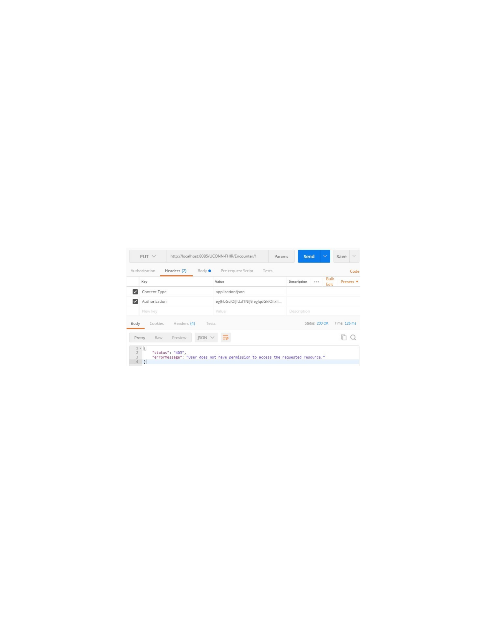
the Postman tool (Postman, 2013) instead of directly made them from ShareMyHealth and
MyGoogle in order to present a clear view of the response the requests can have in different
scenarios. In the first scenario, Figure 6.15, FSICC rejects a request from the user (Sarah) via the
ShareMyHealth (SMH) app to access the global service (PUT Encounter). This is since the user
(SSincs) with user Id (3) is assigned a role (Patient_2) with role Id (4) that is authorized to access
global services 1-5, see global RBAC in Figure 6.9 what does not have access to the global
service (PUT Encounter). Also, the access will also fail since the user (Sarah) has no delegated
roles, see global DAC in Figure 6.13.
Figure 6.15. Access Scenario One (Rejected).
In the second scenario, Figure 6.16, the request from the user (ShareMyHealth) with id (5) via
MyGoogle to access the global service (GET Patient), would be allowed by FSICC. This is since
the user (ShareMyHealth) with user Id (5) is assigned a role (SMH) with role Id (10) that is
authorized to access global services 1-5 that includes (GET Patient), as was shown in the global
RBAC in Figure 6.9. in summary, the three interceptors are utilized in conjunction to
dynamically check each time a user tries to invoke a global Service. All of the conditions must be
satisfied in terms of permissions against the global RBAC, MAC or DAC in order for the service
to be invoked.
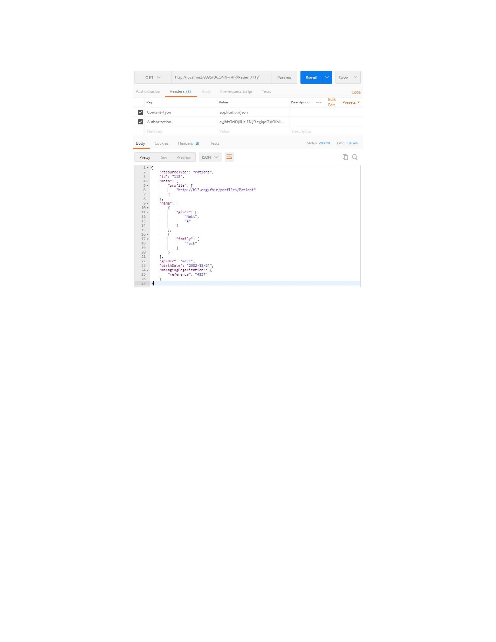
Figure 6.16. Access Scenario Two (Allowed).
6.3. Related work in Security Policy Integration and Enforcement
In this section, we present related work in two areas: security policy integration and security
policies enforcement on FHIR API. For the first area, we review five related works on security
policy integration comparing and contrasting their work to our security policy integration
approach. The first effort (Shafiq, B, Joshi, B, Bertino, E, & Ghafoor, A, 2005) proposed a set of
mapping algorithms that can be utilized to combine RBAC policies from different sources into a
conflict-free global policy. This work is similar to our RBAC integration approach by providing
an RBAC integration solution. However, this work assumes that all of the RBAC policies from
different systems are defined and stored using the same format which is an unrealistic

assumption, while in our approach we require each system to provide an RBAC policy using a
specific format in JSON.
The second effort (Gouglidis, A, Ioannis, M, & Vincent, C, 2014) extended NIST-RBAC to
define a checking technique that can be utilized as a management service/tool for the verification
of multi-domain cloud policies. This technique is capable of detecting whether a user with a role
from one domain can access an object from another domain. This effort, unlike our approach,
does not define a complete global RBAC policy for all of the integrated systems and performs an
on-the-fly authorization query for every object access request that generates an undesirable
overhead.
The third effort (Bonatti, P, Maria, L, & Subrahmanian, V, 1997) focused on the issue of
integrating sensitivity levels of different systems under the assumption that one sensitivity level
in one system may have a different semantic interpretation of the same sensitivity level in
another system. To solve this issue, this effort proposed to map each sensitivity level of each
system with a sensitivity level that has similar semantics but not the same name in another
system. This effort is similar to our MAC integration approach in the way they map a number of
sensitivity levels of different systems which is similar to our mapping of classification levels.
However, the way users and objects of each system assigned clearance and classification,
respectively, in the presence of the global sensitivity levels, is not clearly articulated.
The fourth effort (Dawson, S, Shelly, Q, & Pierangela, S, 2000) proposed an approach for
MAC-based polices integration by introducing two main concepts: the wrapper and the mediator.
A wrapper is a mechanism that is associated with each system to provide a uniform data interface
and a mapping between the system’s sensitivity levels and sensitivity levels of other systems in
order to generate a global MAC policy. The mediator is an enforcement technique that processes

global access requests based on the generated global MAC policy. This work is similar to our
MAC integration approach as they provide a MAC integration solution and also provide a
technique to enforce the global MAC policy. However, their work assumes that each user of each
system can only be assigned to one specific read property (SS) and one specific write property
(SI), unlike our approach where any user may be assigned to any of the read properties (SS, S*
read) and to any of the write properties (SI, L*, S* write).
The last effort (Joshi, BD & Elisa, B, 2006) proposed a solution for defining RBAC-based
delegation in an integrated environment. Specifically, in this work a delegation framework is
proposed that provides two types of delegation, role delegation and permissions (sub-set of
permissions of a role) delegation, that can be user-to-user, user-to-role, role-to-role or role-to-
user. This work is similar to our DAC integration approach as they also provide a DAC
integration solution. However, their work is limited to a specific type of RBAC (i.e., GTRBAC),
unlike our approach for RBAC-based delegation. Also, their work does not support the
integration of MACbased delegation in which our approach provides it. Note that all of the above
five efforts try to integrate policies that are defined against objects (traditional) and just target
one access control model, while our security policy integration approach provides solutions to
integrate policies which are defined against services that access objects in which such policies
can be any combination of RBAC, MAC, and DAC.
For the second area, we review four related works on the topic of security enforcement that
utilizes FHIR. The first effort, SMART on FHIR (SMART on FHIR, 2015), proposed a standard
for authentication and authorization that controls Apps access to FHIR resources based on the
OAuth2 authentication protocol (Cook, 2012). Each App is given a cryptographic Token that has
a number of claims. A claim can be a scope (each App may have one or more scopes) or patient

ID, and the information in the Token is encrypted using the JWT library (JWT Team, 2012). A
scope, such as (scope=user/Patient.read), defines what type of FHIR API an App can access
which allows an App to retrieve all of the Patient data and can be further restricted to only
return the Patient record that matches the patient ID in the App's Token. This effort is similar to
our approach for enforcing security policies since they support security interceptors that perform
authentication and authorization against each request to access services. However, the
authorization interceptor presented by this effort is different from our approach since the
authorization interceptor cannot be used to enforce advanced security policies to control access to
FHIR resources using roles (RBAC), sensitivity levels (MAC), and roles/sensitivity levels
delegations (DAC).
The second effort, Vonk (Simplifier.net, 2018), is an extension of the access control approach
of SMART on FHIR, an implementation of SMART on FHIR standard in which the default
processes for Apps authentication and authorization is based on SMART on FHIR standard.
However, in Vonk, the authentication implementation can be changed from the default OAuth2
authentication protocol to any other authentication implementations and the authorization process
of SMART on FHIR can be replaced with any other authorization implementations. This effort is
similar to our approach for enforcing security policies as their approach provide authentication
and authorization capabilities. However, the authorization process of this effort is different from
our approach as it does not support advanced security requirements to control access to FHIR
resources using roles (RBAC), sensitivity levels (MAC), and roles/sensitivity levels delegations
(DAC).
The third effort, SecFHIR (Altamimi, 2016), proposed a security standard that may be adopted
to extend the FHIR standard with access control specifications. Specifically, SecFHIR suggested

to define permissions on FHIR resources as an XML schema so that the defined XML schema
can be integrated into the XML schemas of different FHIR resources. In this way, the
permissions defined in each FHIR resource’s XML schemas can be utilized by any access control
mechanism to enforce such permissions. Clearly this approach is different from our approach
since SecFHIR does not provide any authentication capabilities that can be utilized to verify the
identity of Apps.
Also, SecFHIR doesn’t provide any mechanisms to support enforcing security policies on Apps’
access requests for important access control models such as RBAC, MAC, and DAC.
Finally, the fourth effort, HAPI FHIR reference implementation (HAPI community, 2017),
provides two security mechanisms: one to verify Apps identity using an authentication
interceptor; and another one to enforce security policies using the rule-based access control
model using the authorization interceptor. The authentication interceptor utilizes the HTTP Basic
Auth protocol for Apps authentication purposes. In addition, the rule-based access control model
defines a set of rules within the interceptor and utilizes if/else statements in order to
whitelist/blacklist Apps access requests to FHIR resources. This approach is similar to our
approach for enforcing security policies as their approach provides authentication and
authorization capabilities, via the authentication and authorization interceptors. However, the
authorization interceptor of their approach is different from our approach as they do not support
advanced security requirements to control access to FHIR resources using roles (RBAC),
sensitivity levels (MAC), and roles/sensitivity levels delegations (DAC).

Chapter 7 SOA-based Security Engineering for FSICC
This chapter presents and explains an SOA-based security engineering and global security policy
generation process for FSICC that involves all of the horizontal boxes in Figure 1.3 that contain
the main research foci of this dissertation: Architectural Blueprints as reviewed in Chapter 5;
Unified Cloud Computing Access Control Model as presented in Chapter 4; Access Control
Models in Section 1.3 of Chapter 1 and Section 2.2 of Chapter 2; and, GSP (Global Security
Policy) Generation and GAPI (Global API) Generation and Global Security Policy and Global
API Utilization and Security Enforcement in Chapter 6. GSP (Global Security Policy)
Generation and GAPI (Global API) Generation is for generating the security policy from
multiple systems to make global APIs available to clients what’s showing in the lower portion of
Figure 1.2 of Chapter 1. Global Security Policy and Global API Utilization and Security
Enforcement that utilizes security interceptors that was shown in the bottom of Figure 1.2 to
allow/deny clients from access global services of FSICC. A SOA-based security engineering
process (SSEP) for FSICC is intended to assist security engineers of systems and clients and
security engineers of
FSICC with a structured process to define and maintain secure interoperable services for RBAC,
MAC, and DAC.
To support SSEP, the Unified Cloud Computing Access Control Model (UCCACM), from
Chapter 4, has a set of definitions for global security policy generation and utilization (see Defns.
41-48 of Section 4.6). This set of definitions ensure that such global security policy can control
access to a set of global services that are generated using one or more of integration architecture

blueprints: Basic Architecture, Alternative Architecture, or Radical Architecture from Chapter 5.
Based on this, this chapter introduces and discusses a SOA-based security engineering and global
security policy generation process for FSICC; this addresses Contribution EC-C: Security
Mapping/Enforcement Algorithms and SSEP from Section 1.5, this is represented by the left
vertical box SOA-BASED SECURITY ENGINEERING in Figure 1.3 from
Chapter 1 that spans all of the five horizontal boxes: Architectural Blueprints, Unified Cloud
Computing Access Control Model, Access Control Models, Global Security Policy and Global
API Generation, and Global Security Policy and Global API Utilization and Security
Enforcement.
In the remainder of this chapter, a SOA-based security engineering and global security policy
generation process for FSICC is presented in three main sections. In Section 7.1, a Pre-Process
Step briefly describes what each system and client need to do before joining the FSICC. In
Section 7.2, a SOA-based security engineering process (SSEP) for FSICC is presented that is
intended to assist security engineers of systems and clients and security engineers of FSICC with
a structured process to define and maintain secure interoperable services for RBAC, MAC, and
DAC. In Section 7.3, a complete and detailed example that illustrates the SOA-based security
engineering process of Section 7.2 is provided to demonstrate the phases and tasks of SSEP
coupled with security policy integration algorithms of Section 6.2 of Chapter 6 that can be
utilized to establish and utilize security for interoperable services via FSICC.
7.1. A Pre-Process Step for Joining FSICC
As discussed in Chapter 3, one key feature of the FSICC is to enable multiple systems to
provide their services, which can be web-based, cloud-based, or traditional API, via registering

into FSICC. This was introduced in Section 3.2 as cloud computing capability 1: Local Service
Registration and Mapping to Global Services. These web-based, cloud-based, or traditional API
that are provided by a system are transitioned to a set of equivalent and unified into a set of
global services, via FSICC, by utilizing cloud computing capability 1. However, as discussed in
Chapter 5, each system that provides services needs to perform a pre-process step before joining
the
FSICC which is creating an integration layer utilizing a standard integration framework
(IFMWK), such as FHIR API for the healthcare domain, which is a standard API that converts
system’s data from/to the integration layer format. Such an integration layer is specified and
utilized by the FCICC. To support this step, Section 5.3 provided a specific set of instructions
using the HIT IFMWK Blueprint that a system may utilize to build its own integration layer.
From a client perspective, FSICC provides the unified Global Services so that clients can
easily create application functionality without the need to consider heterogeneous types of
systems’ services. This was introduced in Section 3.2 as cloud computing capability 3: Global
registration, authentication, authorization, and service discover for Consumers. These mobile,
web, or desktop client apps then can be developed using a subset of the available unified global
services, via FSICC, by utilizing cloud computing capability 3. However, as discussed in Chapter
5, each client that is interested in utilizing such global services may need to perform a pre-
process step before joining the FSICC to create an integration layer which is a standard API that
converts a client’s data from/to the integration layer format. To support this step, Section 5.3
provided three sets of instructions via three architectural blueprint options that a client may
utilize to build its own integration layer: the Basic Architecture Blueprint, the Alternative
Architecture Blueprint, and the Radical Architecture Blueprint).

7.2. An SOA-based Security Engineering Process (SSEP) for FSICC
The SOA-based security engineering process (SSEP) is intended to help security engineers of
systems and clients, on one side, and the security engineer of FSICC, on the other side, to
establish and maintain secure interoperable services via RBAC, MAC, and DAC per security
requirements 2, 4, and 3 of Section 3.1, respectively, as shown in Figure 7.1. This occurs via four
main phases (i.e., 1.a, 1.b, 2.a, and 2.b) in which the phases 2.a, and 2.b are further explained in
Figures 7.2 and 7.3, respectively. This allows SSEP to enable the security engineer: of each
participating system to integrate its services into FSICC (see cloud computing capability 1 of
Section 3.2) in which the system’s security policy is enforced; of each interested client to enable
the client’s users to leverage a set of global services and global security policy (see cloud
computing capability 3 of Section 3.2); and of the FSICC to integrate all of the security policies
from all of systems that are to be defined against the global services (see cloud computing
capability 2 of Section 3.2) and to control the way that interested clients utilize the services. In
the remainder of this section, we explore SSEP in Figure 7.1, along with Figures 7.2 and 7.3,
utilizing Figure 6.1 from Chapter 6 that showed the architecture for global security policy
generation and utilization, and explaining the tasks for security engineers of systems, clients, and
FSICC.
To begin, the SSEP, in Figure 7.1, is divided into four phases. In Section 7.2.1, we present the
Constructing Systems Requests phase, labeled (1.a) in the top left of Figure 7.1, that needs to be
performed by security engineers of systems. In Section 7.2.2, we describe the Constructing
Clients Requests phase, labeled (1.b) in the top right of Figure 7.1, that needs to be performed by
security engineers of clients. In Section 7.2.3, we present the Registering Requests Processing

phase, labeled (2.a) in the bottom left of Figure 7.1, that needs to be performed by the security
engineers of FSICC in which the specific tasks of this phase are depicted in Figure 7.2. In
Section
7.2.4, we discuss the Usage Requests Processing phase, labeled (2.b) in the bottom right of
Figure
7.1, that needs to be performed by the security engineers of FSICC in which the specific tasks of
this phase are depicted in Figure 7.3. Note that in the rest of this section, the term “system”
indicates a pure system, mixed system (services registering part) or mixed client (services
registering part), and the term “client” indicates a pure client, mixed client (services utilization
part) or mixed systems (services utilization part).
7.2.1 Constructing Systems Requests Phase
The Constructing Systems Requests phase labeled (1.a) in Figure 7.1 allows security
engineers of pure or mixed systems to provide their services via FSICC and for mixed systems to
request services. From a registering perspective, security engineers of both pure and mixed
systems can select to Register System’s Integration Layer and Security Policy, labeled (1.a.1)
which utilizes the cloud computing capabilities of FSICC to provide the system’s integration
layer and security policy that enables FSICC to recognize and integrate: a system’s integration
layer with the global services; and, a system’s security policy with the global security policy. This
is indicated by the dashed line from the Constructing Systems Requests box to the Registering
Requests Processing box labeled (2.a) at the bottom left of Figure 7.1. As part of this process, the
system’s integration layer (e.g., FHIR for HITs) can be designed by utilizing the HIT IFMWK
Blueprint from Section 5.3, as described in Section 7.1. In addition, the system’s security policy
is defined by the system’s security engineer to control access to the system’s integration layer via

one or more access control models such as RBAC, MAC, and/or DAC that specify which
services
(of the system’s integration layer) each user in that system may access. This is indicated by the
RBAC Integration and Review & Correct Role Names, the MAC Integration and Building
Global MAC, and the DAC Integration boxes of pure and mixed systems at the bottom of Figure
6.1 from Chapter 6.
From a usage perspective, security engineers of mixed systems can select to Utilize GSP &
GAPI labeled (1.a.3) and since they are interested in using the Global Services in order to
accomplish some of the functionalities, they need to go through a number of tasks based on the
answers to two questions:
•Question 1: Does the mixed system need to utilize a subset of the global services (i.e.,
global API) and a subset of the global security policies, labeled (1.a.q1)? If yes, then
ask Question 2.
•Question 2: Does the mixed system need to customize a subset of the global security
policies, labeled (1.a.q2)? That is, a security engineer of the system has found a global
security policy that has too few/many permissions than needed, thereby needing a
customization.
If the answer to Question 2 was yes, then the security engineer of the system
would need to have human intervention with the security engineer of FSICC,
labeled (1.a.2), to customize a subset of the global security policy in which
both parties discuss and agree about adding a new customized security policy,
the global security policy is updated after this task, or to use an existing
security policy.

If the answer to Question 2 was no, the security engineer of the system would
use some capabilities of FSICC to send a global security policy and global
services utilization request to FSICC, labeled (1.a.3) as indicated by the solid
line from the Constructing Systems Requests box to the Usage Requests
Processing box at the bottom of Figure 7.1.
Legend
----- register security & API ___ utilize security & API
GSP Global Security Policy GAPI Global
API(Services)
Figure 7.1. A High-Level View of SOA-Based Security Engineering Process for FSICC.
7.2.2 Constructing Clients Requests Phase

The Constructing Clients Requests phase labeled (1.b) in Figure 7.1 allows security engineers
of mixed clients to provide their services via FSICC and for pure and mixed clients to request
services. From a registering perspective, security engineers of mixed clients can select to
Register
System’s Integration Layer and Security Policy, labeled (1.b.1) which utilizes the cloud
computing capabilities of FSICC to provide the client’s integration layer and security policy that
enables FSICC to recognize and integrate: a system’s integration layer with the global services;
and, a system’s security policy with the global security policy. This is indicated by the dashed
line from the Constructing Clients Requests box to the Registering Requests Processing box at
the bottom of Figure 7.1. As part of this process, the client’s integration layer (e.g., FHIR for
HITs) can be designed by utilizing the HIT IFMWK Blueprint from Section 5.3, as described in
Section
7.1. Moreover, the client’s integration layer (e.g., FHIR for HITs) can be designed by utilizing
one of the three integration options: Basic Architecture, Alternative Architecture, or Radical
Architecture as discussed in Section 5.2, as described in Section 7.1. In addition, the client’s
security policy is defined by the client’s security engineer to control access to the client’s
integration layer via one or more access control models such as RBAC, MAC, and/or DAC that
specify which services (of the client’s integration layer) each user in that client may access, this
is indicated by the RBAC Integration and Review & Correct Role Names, the MAC Integration
and Building Global MAC, and the DAC Integration boxes of mixed clients at the top of Figure
6.1.
From a usage perspective, security engineers of pure and mixed clients that are interested in
utilizing the FSICC’s global services and global security policy in order to accomplish some of

the functionalities, need to go through a number of tasks based on the answers to three questions.
•Question 1: Does the client have a defined security policy that the client’s security
engineer prefers to use instead of the global security policy (1.b.q1)?
If the answer to Question 1 was yes, then the security engineer of the client has
human intervention with the security engineer of FSICC to map the client’s
security policy to the global security policy labeled (1.b.2) in which both parties
discuss and agree about a way to map the client’s security policy to the global
security policy which is updated after this task.
If the answer to Question 1 was no, the client’s security engineer needs to answer
Question 2.
•Question 2: Does the client need to utilize a subset of the global services (i.e., global
API) and a subset of the global security policies, labeled (1.b.q2)? If the answer to
Question 2 was no, the client’s security engineer needs to answer Question 3.
•Question 3: Does the client need to customize a subset of the global security policies,
labeled (1.b.q3)? That is, a security engineer of a client has found a global security
policy that has too few/many permissions than needed, thereby needing a
customization.
If the answer to Question 3 was yes, then the security engineer of the client would
need to have human intervention with the security engineer of FSICC to
customize a subset of the global security policy, labeled (1.b.3), in which both
parties discuss and agree about adding a new customized security policy, the
global security policy is updated after this task, or to use an existing security
policy.

If the answer to Question 3 was no, the security engineer of the client would use
some capabilities of FSICC to send a global security policy and global services
utilization request to FSICC, labeled (1.b.4) indicated by the solid line from the
Constructing Clients Requests box to the Usage Requests Processing box at the
bottom of Figure 7.1.
7.2.3 Registering Requests Processing Phase
The Registering Requests Processing phase labeled (2.a) in Figure 7.1 needs to be performed
by the security engineers of FSICC to achieve two main objectives. First, to build the global
services, which is primarily a human-based process, based on the integration layer of each
system.
Second, to construct the global security policy, which is mostly an algorithm-based process,
based on security policy of each system. The Registering Requests Processing phase has three
tasks and executed for each system that is being integrated into the global policy:
•Task 1: The first task is to configure the global services (global API), labeled (2.a.1)
at the top of Figure 7.2, in which the FSICC’s security engineer is required to
configure each global service of the FSICC so that CRUD methods of the services
can send and receive data to/from each system’s integration layers. This is based on
integration layers provided by different systems in the phases 1.a and 1.b of Figure
7.1.
•Task 2: In the second task, the FSICC’s security engineer has three task options to
perform RBAC, MAC, and/or DAC integration on each system, which may have no

access control, only one access control, any combination of two access controls, or all
three access controls:
The first task option, labeled (2.a.2) in Figure 7.2, is to send each RBAC policy of
each system to the RBAC integration algorithm. This task option is performed if
there is a system’s RBAC policy that needs to be integrated with the global
security policy. As part of this process, the generated RBAC policy is submitted to
Review and Correct Role Names Algorithm labeled (2.a.2.a) with any other
required input.
The second task option, labeled (2.a.3) in Figure 7.2, is to send each MAC policy
of each system to the MAC integration algorithm. This task option is performed if
there is a system’s MAC policy that needs to be integrated with the global security
policy. As part of this process, the generated Sensitivity Levels Mapping List is
submitted to the Building Global MAC Algorithm with any other required inputs,
labeled (2.a.3.a).
The third task option, labeled (2.a.4) in Figure 7.2, is to send each DAC policy of
each system to the DAC integration algorithm. This task option is performed if
there is a system’s DAC policy that needs to be integrated with the global security
policy.
•Task 3: In third task, labeled (2.a.5) at the bottom of Figure 7.2, the FSICC’s security
engineer needs to send the resulted global RBAC policy from (2.a.2), global MAC
policy from (2.a.3), and global DAC policy from (2.a.4) to Combine Updated Global
RBAC, Global MAC, and Global DAC and Control Data algorithm that concatenates
all of the three global polices to generate one global security policy. The FSICC’s

security engineer also needs to specify one read data access type, as described in
Section 6.1.4 of Chapter 6, to control the way that data are read. Note that there is one
write data access type that is used by default to control the way that data are written.
The third task marks the final part of the Registering Requests Processing phase in
which the global services and global security policy are ready to be utilized by
FSICC’s clients. Moreover, at this point the complete details of the generated global
security policy and global services, such as the way to utilize the global services and
global security policy and what is the exact web location, will not be published to
public.
Figure 7.2. A Detailed View of Phase 2.a of the SSEP
7.2.4 Usage Requests Processing Phase
The Usage Requests Processing phase labeled (2.b) in Figure 7.1 is performed by the security
engineers of FSICC to enable clients to leverage available global services and the corresponding
global security policy, which are built based on the tasks of the Registering Requests Processing
phase and is a human-based process. The FSICC’s security engineer has four tasks to perform the
Usage Requests Processing phase:
(2.a) Registering Requests Processing
Send RBAC of System to (2.a.2)
RBAC Integration Algorithm
Send MAC of System to MAC (2.a.3)
Integration Algorithm
Send DAC of System to DAC (2.a.4)
Integration Algorithm
NEEDS RBAC
INTEGRATION
]DONE[
[ ]NOT DONE
DONE[ ]
]NOT DONE[
]DONE[
NOT DONE ][
Send Global RBAC to Review & (2.a.2.a)
Correct Role Names Algorithm (with
needed input)
][DONE
][NOT DONE
Send the Sensitivity Levels (2.a.3.a)
Mapping List to Building Global MAC
Algorithm (with needed input)
]DONE[
]NOT DONE[
Combine Updated Global (2.a.5)
RBAC, Global MAC and Global DAC
& Control Data to Generate Global
Security Policy ]DONE[
NOT DONE ][
]NEEDS REVISION[
(2.a.1) Configure Global API
DONE[ ]
NOT DONE ][
NO[ ]
]YES[
NEEDS MAC
INTEGRATION
[ ]NO
][YES
NEEDS DAC
INTEGRATION
NO][
YES][

•Task 1: In the first task, the FSICC’s security engineer has three task options to
process clients’ requests:
The left task option, labeled (2.b.1) in Figure 7.3, is to check the Global Security
Policy (GSP) to Find Permissions Similar to Client Security Policy (CSP). This
task option is performed if there is a client that requests to map its security policy
with the global security policy.
The center task option, labeled (2.b.2) in Figure 7.3, is to assign an ID and Token
to a Client which is needed for authentication and authorization purposes. This
task option is performed if there is a client (basically all of the clients) that
requests to utilize a subset of the global security policy and global services.
The right task option, labeled (2.b.3) in Figure 7.3, is to Add needed Customized
Policy to GSP as a New Policy. This task option is performed if there is a client
that requests to customize a subset of the global security policy.
•Task 2: In the second task, the FSICC’s security engineer also has three task options:
The left task option, labeled (2.b.1.a) in Figure 7.3, is to map the Client Security
Policy (CSP) and Global Security Policy (GSP). This task option is performed if
the output of the task option (2.b.1) was yes, which means that the Global
Security Policy (GSP) has permissions similar to Client Security Policy (CSP).
The center task option, labeled (2.b.1.b) in Figure 7.3, is to add the Client Security
Policy (CSP) to Global Security Policy (GSP). This task option is performed if the
output of the task option (2.b.1) was no, which means that the Global Security
Policy (GSP) does not have permissions similar to Client Security Policy (CSP).

The right task option, labeled (2.b.2.a) in Figure 7.3, is to Find One Suitable
System for a Client as a Repository. This can be done by finding a registered
system that provides services similar to the set of global services the client is
interested in.
•Task 3: In the third task, labeled (2.b.4) in Figure 7.3, the FSICC’s security engineer
should update the Global Security Policy (GSP,) that may have been changed as a
result of performing the tasks (2.b.1.a), (2.b.1.b) and/or (2.b.3).
•Task 4: In the fourth task, labeled (2.b.5) in Figure 7.3, the FSICC’s security engineer
can Send to the client: the Client’s ID, the Client’s Security Token, the available
Global API (services), the available Global Security Policy (GSP), and instructions on
the way to utilize such global services and global security policy. This allows the
client to begin building an App utilizing the retrieved global services and global
security policy.
Legend
CSP Client Security Policy GSP Global Security Policy
Figure 7.3. A Detailed View of Phase 2.b of the SSEP
7.3. Demonstrating the SOA-based Security Engineering Process
To provide a hands-on experiment on the SOA-based security engineering process (SSEP),
this section presents a complete and detailed example that demonstrates: the way that each phase
and task of SSEP from Section 7.2 in applied, as was shown in Figures 7.1, 7.2, and 7.3; the
usage of the security policy integration algorithms from Section 6.1 from Chapter 6, see Figures
6.1-6.8; and, the establishment and utilization of security for interoperable services via FSICC.
In the remainder of this section, our healthcare scenario from Section 2.4 is used for explaining
all of the phases and tasks of SSEP, where we assume that the CT2 client does not provide
services or a security policy. Based on this assumption, we can categorize: CT2 App as a pure
client that only utilizes services from OpenEMR system; SMH App as a mixed client that
Usage Requests Processing(2.b)
Assign ID & Token to a Client(2.b.2)
Check GSP to Find (2.b.1)
Permissions Similar to CSP
[CLIENT REQUEST TO MAP CSP WITH GSP ]
Add Needed Customized (2.b.3)
Policy to GSP as a New Policy
][CLIENT REQUEST TO CUSTOMIZE GSP
]CLIENT REQUEST TO UTILIZE GSP & Global API[
FOUND
]YES[
]NO[
Find One Suitable System (2.b.2.a)
for a Client as Repository
Update GSP if Needed(2.b.4)
Add CSP to GSP(2.b.1.b)
Send: Client ‘s ID & Token, (2.b.5)
the Available Global API, and the
Available GSP to a Client [DONE]
]NOT DONE[
[NEEDS REVISION]
(2.b.1.a) Map CSP and
GSP

utilizes services from MyGoogle system and provides a number of services; OpenEMR as a
pure system that only provides services; and, MyGoogle as a mixed system that provides
services and utilizes services from OpenEMR.
Using this setting, we apply the SSEP’s phases and tasks of Section 7.2 in the following order.
First, the Constructing Systems Requests phase, labeled (1.a) in the top left of Figure 7.1, is
applied to OpenEMR system, MyGoogle system, and SMH client App, since each of them has
services and security policy to register. Second, the Registering Requests Processing phase,
labeled (2.a) in the bottom left of Figure 7.1, is applied to OpenEMR system, MyGoogle system,
and SMH client App, since each of them has sent services and security policy registering requests
to FSICC. Third, the Constructing Clients Requests phase, labeled (1.b) in the top right of Figure
7.1, is applied to MyGoogle system, SMH, and CT2 client Apps, since each of them is interested
in utilizing the global services and the global security policy. Finally, the Usage Requests
Processing phase, labeled (2.b) in the bottom right of Figure 7.1, is applied to MyGoogle system,
SMH, and CT2 client Apps, since each of them has sent global services and global security
policy utilization requests to FSICC. Note that in the remainder of this section, only a subset of
actual services and security policies of each system and client is used, since these subsets are
enough for explaining all of the phases and tasks of SSEP.
The remainder of this section is organized into four subsections. In Section 7.3.1, we explain
the way that the three systems OpenEMR, MyGoogle, and SMH can utilize the Constructing
Systems Requests phase from Section 7.2. In Section 7.3.2, we apply the Registering Requests
Processing phase from Section 7.2 to the three requests from OpenEMR, MyGoogle, and SMH
systems. In Section 7.3.3, we explain the way that three clients: MyGoogle, SMH, and CT2 can
utilize the Constructing Clients Requests phase from Section 7.2. Finally, in Section 7.3.4, we

apply the Usage Requests Processing phase from Section 7.2 to the three requests from
MyGoogle, SMH, and CT2 clients.
7.3.1 Applying the Constructing Systems Requests Phase on OpenEMR, MyGoogle, and
SMH
In this section, we apply the Constructing Systems Requests phase, labeled (1.a) in Figure 7.1,
to the OpenEMR and MyGoogle systems and the SMH client. Since OpenEMR is a pure system,
the security engineer of OpenEMR must register: OpenEMR’s integration layer which are
OpenEMR’s FHIR services in Table 2.5 of Section 2.4 and Example 4.4 with Figure 4.1 in
Section 4.4; and, OpenEMR’s security policy which are OpenEMR’s RBAC, MAC, and DAC in
Table 2.6 of Section 2.4 and Example 4.4 with Figure 4.1 in Section 4.4. Note that the security
engineer of the OpenEMR system designed the OpenEMR’s integration layer by utilizing the
HIT IFMWK Blueprint in Section 5.4.1. This can be achieved by constructing three JSON
documents, one for OpenEMR’s FHIR services from Figure 7.4, one for OpenEMR’s
RBAC/DAC from
Figure 7.5, and one for OpenEMR’s MAC/DAC from Figure 7.6, and then sending them to the
System Registry component of FSICC in Figure 7.22.
Figure 7.4. OpenEMR’s FHIR services in JSON
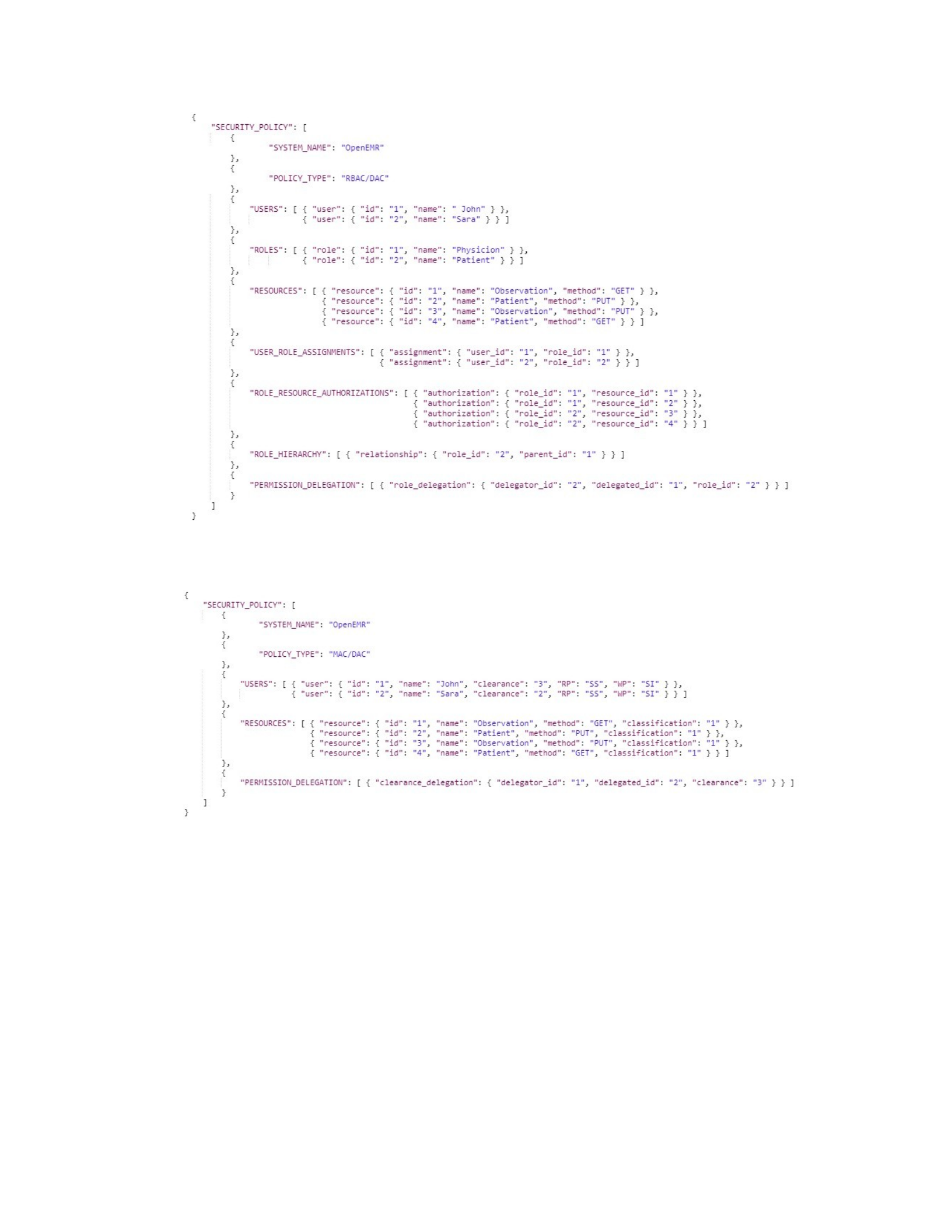
Figure 7.5. OpenEMR’s RBAC/DAC policy in JSON
Figure 7.6. OpenEMR’s MAC/DAC policy in JSON
Second, we apply the Constructing Systems Requests phase, labeled (1.a) in Figure 7.1, to the
MyGoogle system. Since MyGoogle is a mixed system, the security engineer of MyGoogle, must
register: MyGoogle’s integration layer which are the MyGoogle’s FHIR services in Table 2.7 of
Section 2.4 and Example 4.4 with Figure 4.1 in Section 4.4; and MyGoogle’s security policy
which are the MyGoogle’s RBAC and MAC in Table 2.8 of Section 2.4 and Example 4.4 with
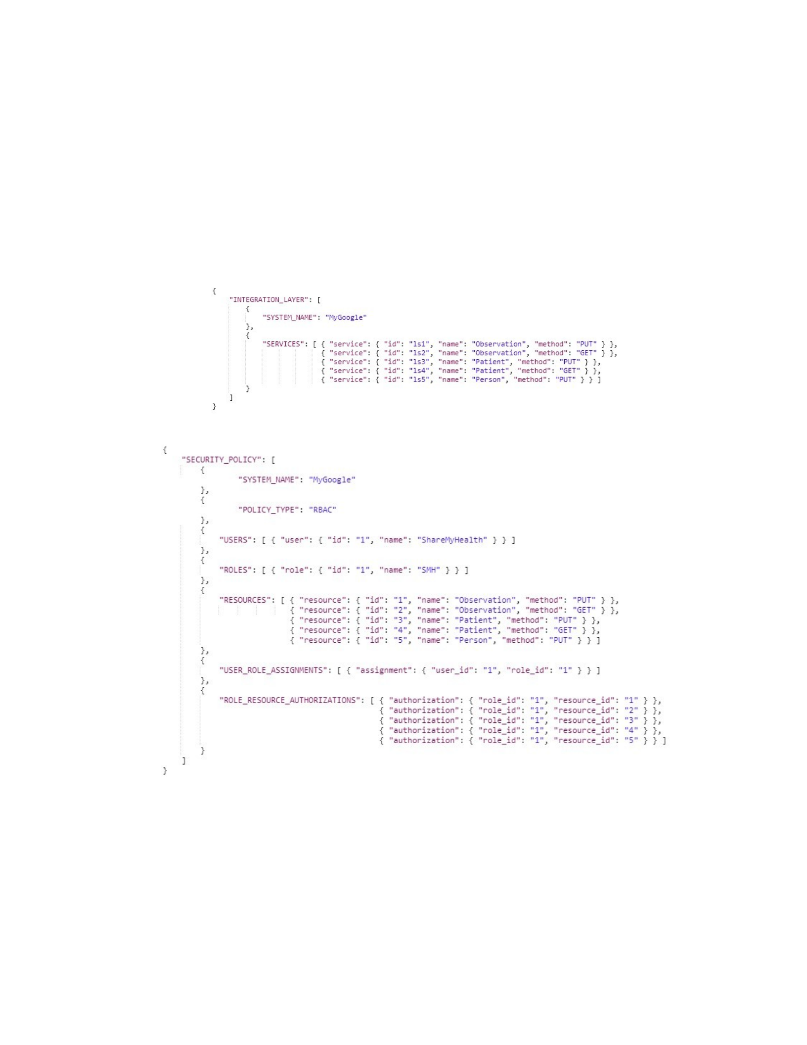
Figure 4.1 in Section 4.4. Note that the security engineer of the MyGoogle system designed the
MyGoogle’s integration layer by utilizing the HIT IFMWK Blueprint in Section 5.4.1. This can
be achieved by constructing three JSON documents, one for MyGoogle’s FHIR services from
Figure 7.7, one for MyGoogle’s RBAC from Figure 7.8, and one for MyGoogle’s MAC from
Figure 7.9, and then sending them to System Registry component of FSICC see Figure 7.22.
Figure 7.7. MyGoogle’s FHIR services in JSON
Figure 7.8. MyGoogle’s RBAC policy in JSON
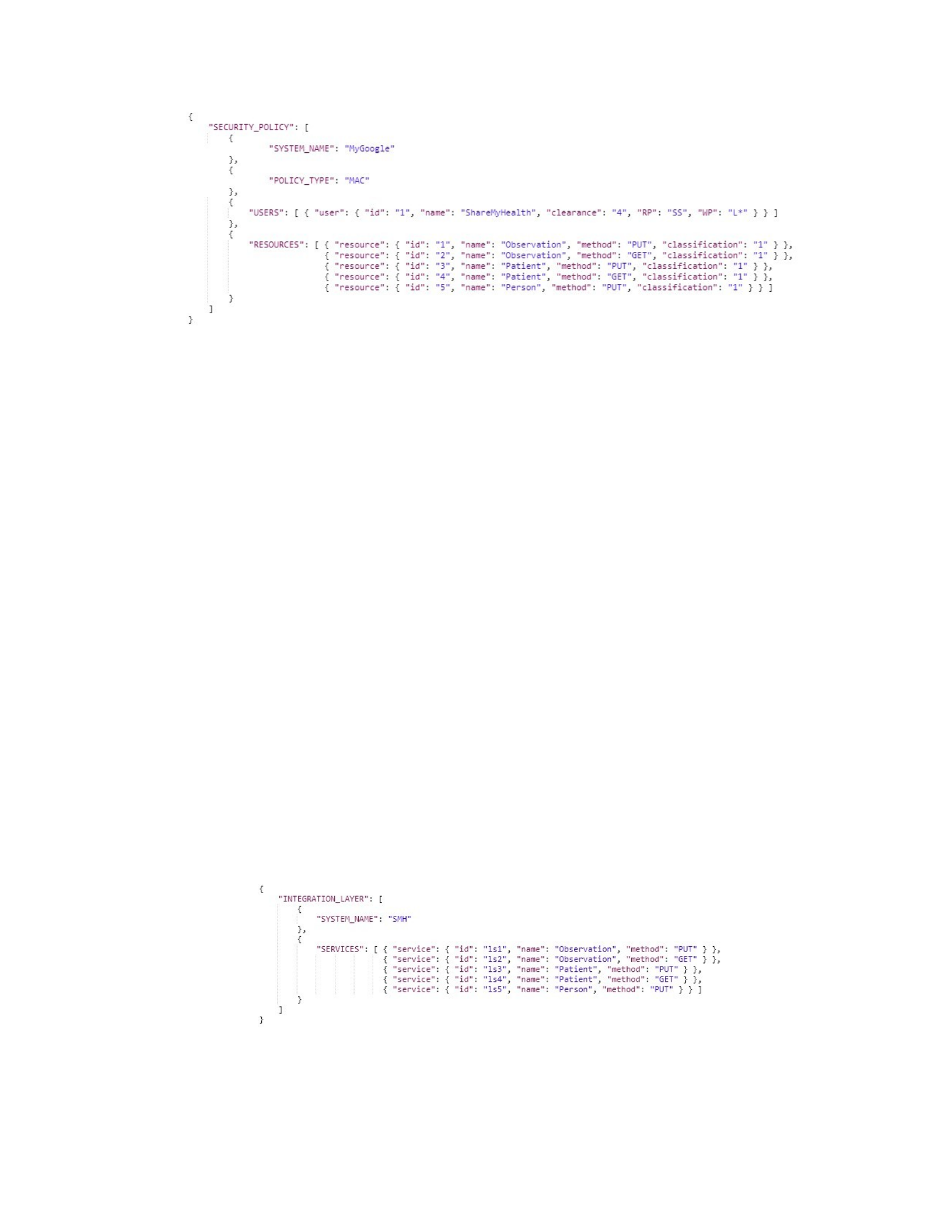
Figure 7.9. MyGoogle’s MAC policy in JSON
Finally, we apply the Constructing Systems Requests phase, labeled (1.a) in Figure 7.1, to the
SMH client App. Since SMH is a mixed client, the security engineer of SMH must register:
SMH’s integration layer which are SMH’s FHIR services see Table 2.3 in Section 2.4 and
Example 4.5 with Figure 4.2 in Section 4.4; and, SMH’s security policy which are SMH’s
RBAC, MAC, and DAC see Table 2.4 in Section 2.4 and Example 4.5 with Figure 4.2 in Section
4.4. Note that the security engineer of the SMH designed the SMH’s integration layer by utilizing
the Basic Architecture Blueprint in Section 5.4.1. This can be achieved by constructing three
JSON documents, one for SMH’s FHIR services from Figure 7.10, one for SMH’s RBAC/DAC
from
Figure 7.11, and one for SMH’s MAC from Figure 7.12, and then sending them to the System
Registry component of FSICC see Figure 7.22.
Figure 7.10. SMH’s FHIR services in JSON
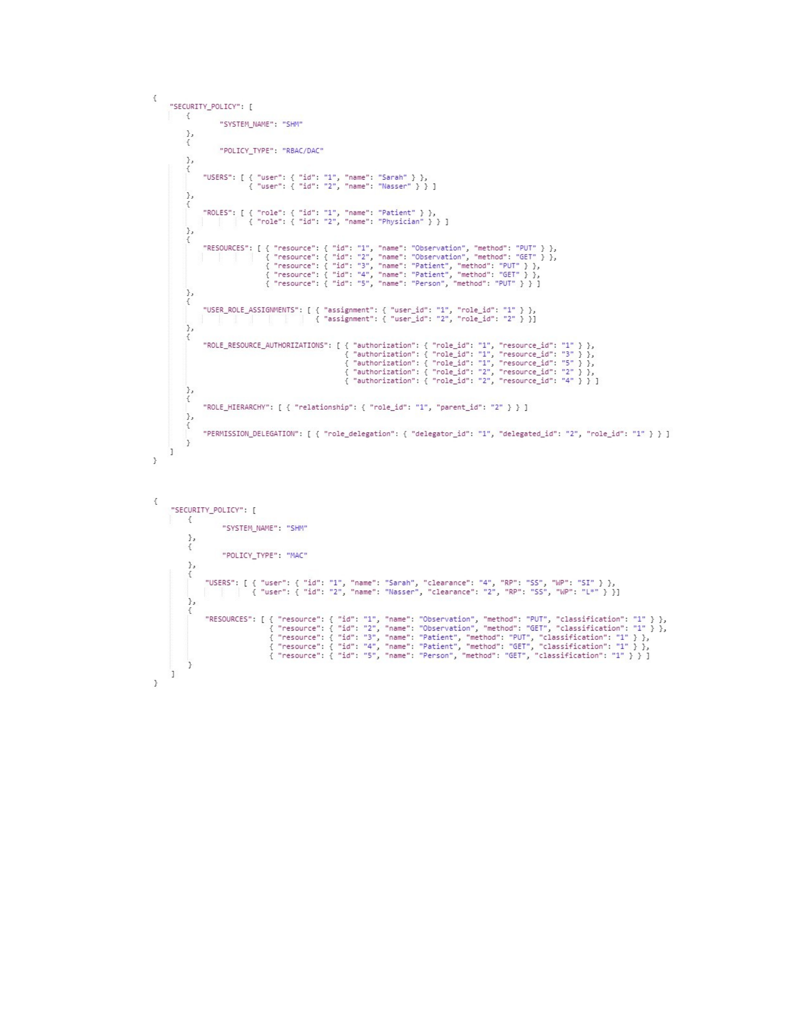
Figure 7.11. SMH’s RBAC/DAC policy in JSON
Figure 7.12. SMH’s MAC policy in JSON
7.3.2 Applying the Registering Requests Processing Phase on OpenEMR, MyGoogle, and
SMH
In this section, we apply the Registering Requests Processing Phase, labeled (2.a) in Figure
7.1, to the OpenEMR, MyGoogle systems and the SMH client. In Section 7.3.1, OpenEMR,
MyGoogle, and SMH were constructed and sent a registering request in JSON format to the

FSICC, see Figures 7.4, 7.7, and 7.10 respectively. In this phase, the security engineer of FSICC,
as described in Section 7.2.3 and Figure 7.2, processes each of these registering requests through
the three tasks as described in Section 7.2.3.
In task 1, the security engineer of FSICC needs to configure each global service of the FSICC
so that CRUD methods of the global services can send and receive data to/from the integration
layers of OpenEMR, MyGoogle, and SMH. In this task, the security engineer of FSICC reads the
JSON documents that include the registering requests of OpenEMR, MyGoogle, and SMH and
initializes the global services of FSICC with five services as presented in Table 7.1. For example,
the service (gs2) is a global service (Observation[GET]) that whenever triggered calls the mapped
services ls2 of OpenEMR, ls2 of MyGoogle, and ls2 of SMH. Similarly, the services (gs1, gs3, gs4,
gs5) are created and configured as described in Table 7.1. Note that for each created global
service, only the specified CRUD methods of the mapped service are implemented. For example,
only PUT and GET methods are implemented for the first global service (gs1) but not POST or
DELETE methods.
Table 7.1. Initial Set of FSICC’s Global Services
Service ID Service Name Method Name Mapped to
gs1 FSICC/Observation PUT ls1 (OpenEMR), ls1 (MyGoogle), and ls1 (SMH)
gs2 FSICC/Observation GET ls2 (OpenEMR), ls2 (MyGoogle), and ls2 (SMH)
gs3 FSICC/Patient PUT ls3 (OpenEMR), ls3 (MyGoogle), and ls3 (SMH)
gs4 FSICC/Patient GET ls4 (OpenEMR), ls4 (MyGoogle), and ls4 (SMH)
gs5 FSICC/Person PUT ls5 (MyGoogle), and ls5 (SMH)
In task 2, to establish the global security policy the security engineer of FSICC needs to send
the registered security policy of OpenEMR, MyGoogle, and SMH to the appropriate task 2
option based on the type of the registered security policy (RBAC, MAC, or DAC). First, as
described in the first task option of task 2 labeled 2.a.2 in Section 7.2.3, the security engineer of

FSICC sends the OpenEMR’s RBAC policy, Figure 7.5, MyGoogle’s RBAC policy, Figure 7.8,
and SMH’s
RBAC policy, Figure 7.11, to the RBAC integration algorithm that generates the initial global
RBAC policy as shown in Figure 7.14. Moreover, Table 7.2 has some information that the
Global-RBAC algorithm uses to generate the initial global RBAC policy given in Figure 7.14.
First, the algorithm uses the RBAC policy of OpenEMR to initialize the global RBAC policy so
that OpenEMR’s roles, Physician and Patient, are added as the first two global roles. Then, the
RBAC policy of SMH is integrated to the global RBAC policy so that six global roles,
Physician_2, Patient_2, New_Role_1, New_Role_2, New_Role_3 and New_Role_4, are added
(see the first four comparisons in Table 7.2). Finally, the RBAC policy of MyGoogle is integrated
to the global RBAC policy so that two global roles, SMH and New_Role_5, are added (see the
last eight comparisons in Table 7.2). Note that roles New_Role_1, New_Role_2, New_Role_3,
New_Role_4 and New_Role_5 are abstract roles in which no users are assigned to them. Figure
7.13 provides a clear view of the role hierarchy of the global RBAC policy.
Table 7.2. Comparisons Information of the RBAC Integration Step
ID System Role Global Role Direct Common
Permissions
Comparison
Result
Created Global Roles
1 Physician Physician Observation [GET] Overlap Physician_2, New_Role_1
2 Physician Patient Patient [GET] Overlap New_Role_2
3 Patient Physician Patient [PUT] Overlap Patient_2, New_Role_3
4 Patient Patient Observation [PUT] Overlap New_Role_4
5 SMH New_Role_1 Observation [GET] SR contains GR SMH
6 SMH New_Role_2 Patient [GET] SR contains GR Nothing
7 SMH New_Role_3 Patient [PUT] SR contains GR Nothing
8 SMH New_Role_4 Observation [PUT] SR contains GR Nothing
9 SMH Physician Nothing Not related Nothing
10 SMH Physician_2 Nothing Not related Nothing
11 SMH Patient Nothing Not related Nothing
12 SMH Patient_2 Person [PUT] Overlap New_Role_5

Figure 7.13. The Role Hierarchy of the Global RBAC Policy
RootRole
NewRole_4 NewRole_1NewRole_3 NewRole_2
Physician Physician_2
Patient
Patient_2
SMH
NewRole_5
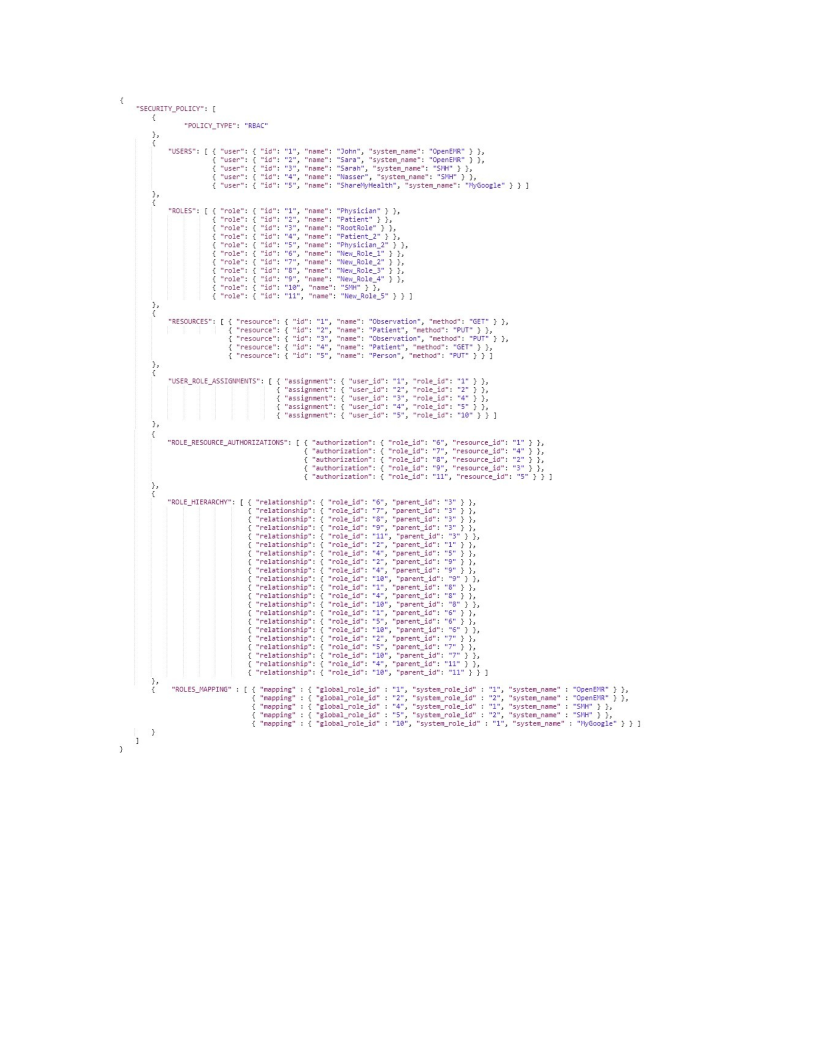
Figure 7.14. The Initial Global RBAC Policy in JSON
Second, as described in the second task option of task 2 labeled (2.a.3) in Section 7.2.3, the
security engineer of FSICC and each of the security engineers of OpenEMR, SMH, and
MyGoogle systems have a discussion in order to understand the semantic and usages of each
sensitivity level of each system. In this case, the assumption is that all of the security engineers of

systems and FSICC have agreed to use different semantics of sensitivity levels, see Section 4.4 of
Chapter 4, and thus generate a Sensitivity Levels Mapping List as described in Table 7.3. Note
that in this example, the OpenEMR’s sensitivity levels set is used as an initial global sensitivity
levels set. In this sensitivity levels mapping list, we can describe the differences in sensitivity
levels as follows: ShareMyHealth’s sensitivity level SIS is mapped to global sensitivity level
SID; while MyGoogle’s sensitivity level VSI is mapped to global sensitivity level SID. Note that
global sensitivity levels SIS and VSI have no corresponding levels in ShareMyHealth and
MyGoogle sensitivity levels, respectively.
Table 7.3. An Example of a Sensitivity Levels Mapping List
ID Global Sensitivity Level (OpenEMR) System Sensitivity Level System Name
1 PI PI ShareMyHealth
2 BSI BSI ShareMyHealth
3 SIS - ShareMyHealth
4 SID SIS ShareMyHealth
5 VSI VSI ShareMyHealth
6 PI PI MyGoogle
7 BSI BSI MyGoogle
8 SIS SIS MyGoogle
9 SID VSI MyGoogle
10 VSI - MyGoogle
Third, as described in the third task option of task 2 labeled (2.a.4) in Section 7.2.3, the
security engineer of FSICC is required to send the DAC policy of OpenEMR, Figures 7.5 and
7.6, and DAC policy of SMH, Figure 7.11, to the DAC Integration algorithm that generates the
global DAC policy as shown in Figure 7.15. Note that MyGoogle has no DAC policy. The
generated global DAC policy has two role delegations (one from OpenEMR and one from SMH),
and one clearance delegation from OpenEMR. Note that the Global DAC algorithm changed the
role Ids, clearance, and user Ids to the global equivalents.
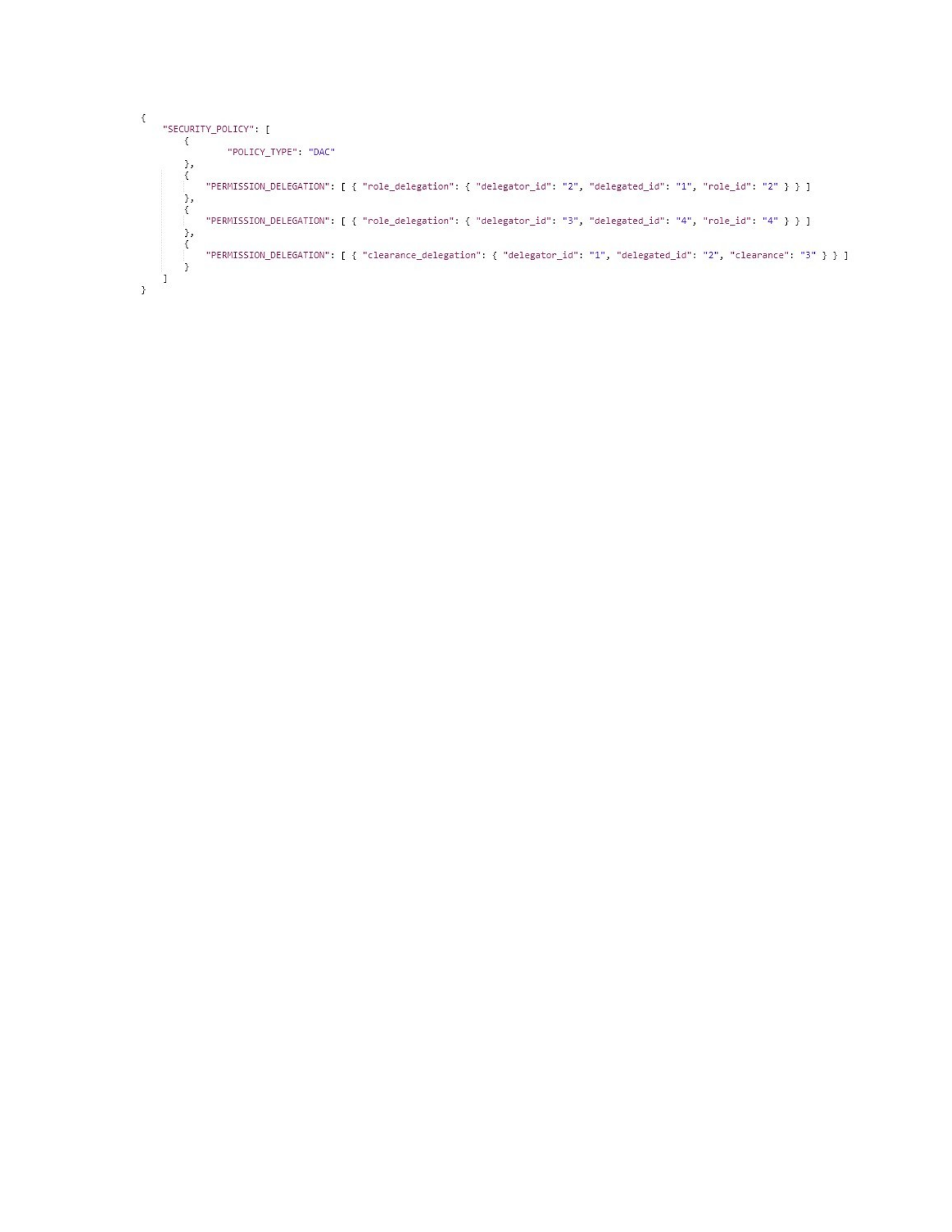
Figure 7.15. The Global DAC Policy in JSON
In task 2, to finalize the generation of the global RBAC policy and global MAC policy the
security engineer of FSICC also needs to send the output of the first task option, labeled (2.a.2),
of task 2 and the second task option, labeled (2.a.3), of task 2 to the appropriate remaining part of
each task option, labeled (2.a.2.a) and (2.a.3.a) in Figure 7.2 respectively, based on the type of
the registered security policy (RBAC or MAC). First, after generating the initial global RBAC
labeled (2.a.2), Figure 7.14, that has some global roles with undesirable names such as
New_Role_1 - New_Role_5, the security engineer of FSICC may wish to rename such roles via
the step labeled (2.a.2.a) in Figure 7.2. To do this, the security engineer of FSICC first can review
the names of all of the global roles, Figure 7.14, and suggest a new name for a subset of the
global roles, e.g., based on the authorized permissions, as a corrected global roles list. In this
case, the security engineer of FSICC would keep the role names New_Role_1 - New_Role_5 and
change the role names Physician, Patient, Physician_2, and Patient_2 to Attending_Physician,
General_Patient, Research_Physician, and Fitness_Patient, respectively, as described in Table
7.4. Then, the security engineer of FSICC, as described in the first task option of task 2 in
Section 7.2.3, needs to send the corrected global roles list to the Review and Correct Role Names
algorithm labeled 2.a.2.a which updates the global RBAC policy with the new role names as
required.
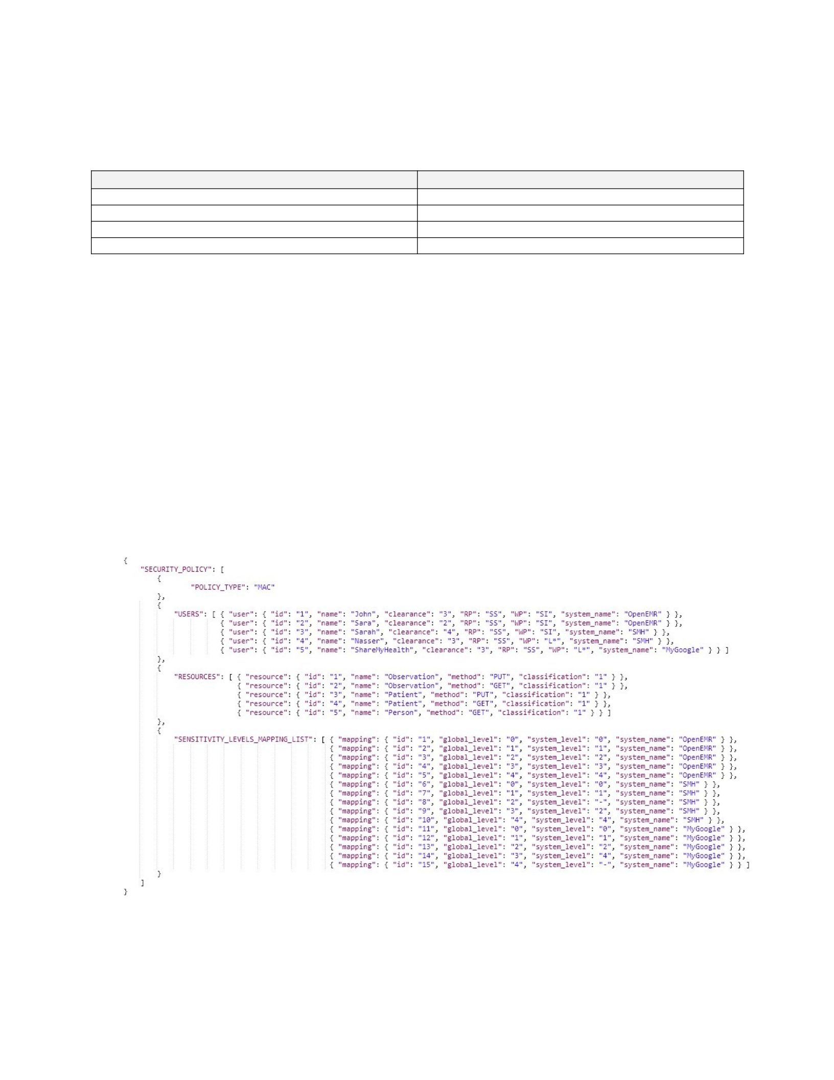
Table 7.4. An Example of a Corrected Global Roles List
Global Role ID (Old Name) New Name
1 (Physician) Attending_Physician
2 (Patient) General_Patient
5 (Physician_2) Research_Physician
4 (Patient_2) Fitness_Patient
Second, as described in the second task option of task 2 labeled (2.a.3) in Section 7.2.3, the
security engineer of FSICC needs to Send the generated Sensitivity Levels Mapping List (Table
7.3) to the Building Global MAC algorithm, labeled (2.a.3.a). This step composes the global
MAC policy, Figure 7.16, utilizing users and services from MAC policy of OpenEMR, Figure
7.6, MyGoogle, Figure 7.9, and SMH, Figure 7.12, in which users clearances and services
classifications are assigned based on the global sensitivity levels in which the read/write
properties of each user are remain unchanged.
Figure 7.16. The Global MAC Policy in JSON

In task 3 labeled (2.a.5) in Section 7.2.3, the global RBAC policy, Figure 7.14, the global
MAC policy, Figure 7.16, and the global DAC policy, Figure 7.15, are simply combined,
utilizing the Combine Updated Global RBAC, Global MAC, and Global DAC and Control Data
algorithm, in one JSON document that serves as the global security policy. Also, the security
engineer of FSICC augments the global security policy with two pieces of information: one of
the three read data access types, and the write data access type (i.e., Open to Same System Users)
as described in Section 6.1.4 of Chapter 6. In this case, the assumption is that the security
engineer of FSICC chosen to use the default read data access type (type 1 Open to All). Based on
these settings: any user from OpenEMR, MyGoogle, or SMH who are assigned to the same
global role, can read any data that the global role can retrieve; and, a user from a specific system,
OpenEMR for example, who is assigned to a global role can only write data (only data of
OpenEMR) that the global role can write.
In summary, at this point of the example and the process, the complete details of the generated
global security policy and global services (such as the way that to utilize the global services and
global security policy) are not as yet published to the public.
7.3.3 Applying the Constructing Clients Requests Phase on MyGoogle, SMH, and CT2
We start by applying the Constructing Clients Requests phase, labeled (1.b) in Figure 7.1, to
MyGoogle system. Since MyGoogle is a mixed system, the security engineer of MyGoogle, from
a usage perspective, needs to answer the three main questions, as discussed in Section 7.2, see
Figure 7.1, after visiting the available global services and global security policy webpage. In this
case, it is assumed that the security engineer of MyGoogle has the following answers: the client
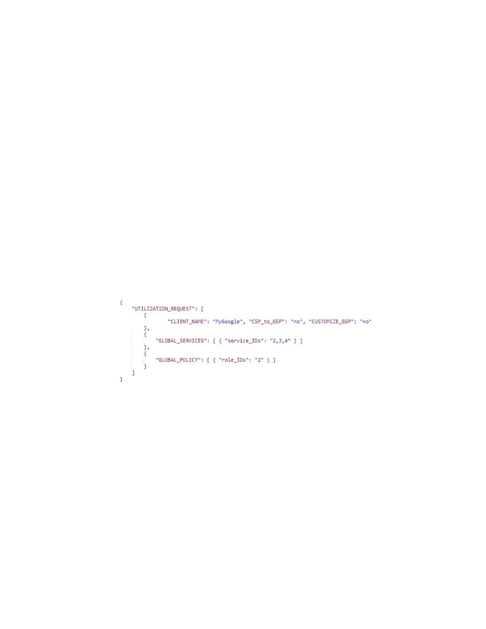
has no defined security policy (again from usage perspective); the client would utilize a subset of
the available global services and global security policy; and, the client does not need to
customize any subset of the global security policies. Based on these answers, the security
engineer of MyGoogle should construct a JSON document for MyGoogle utilization request that
specifies in detail the subset of global services (see Table 7.1) and global security policy, see
Figures 7.14,
7.15, and 7.16, that MyGoogle has interests in utilizing, as shown in Figure 7.17, in which
MyGoogle would be assumed to utilize: the global services: 2, 3, and 4; and the global role 2.
Finally, the security engineer of MyGoogle needs to send the JSON document to the Client
Registry component of FSICC in Figure 7.22.
Figure 7.17. MyGoogle Utilization Request in JSON
Second, we apply the Constructing Clients Requests to the SMH client App. Since SMH is a
mixed client, the security engineer of SMH, from a usage perspective, needs to answer the same
three main questions: SMH client has a defined security policy (again from usage perspective);
SMH client would utilize a subset of the available global services but not interested in the global
security policy; and, the client does not need to customize any subset of the global security
policies. Based on these answers, the security engineer of SMH should construct two JSON
documents. The first one (Policy Mapping Request) is to specify the defined security policy
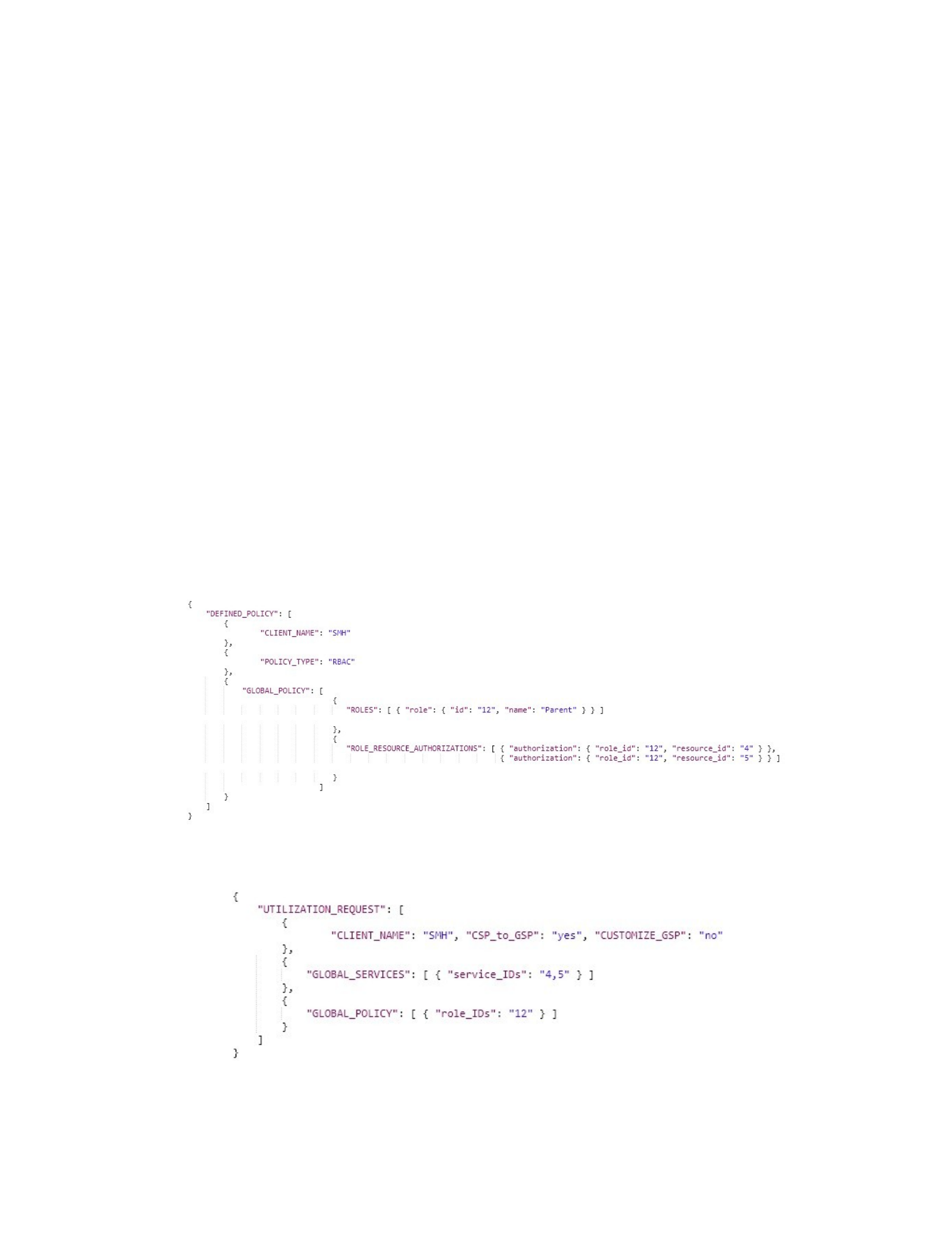
against the global services, as shown in Figure 7.18, in which one role (i.e., Parent with id 12) is
defined that is authorized to access global services 4 and 5. This first JSON document needs to be
sent to the security engineer of FSICC who needs to process and update the global security
policy.
Based on the updated global security policy, the second JSON document can be constructed for
SMH utilization request that specifies in details the subset of global services (see Table 7.1) that
SMH interests in, as shown in Figure 7.19, in which SMH would be assumed to utilize: the
global services: 4 and 5; and the global role 12 which was added into the global security policy as
a result of human intervention with the security engineer of FSICC. Finally, the security engineer
of SMH needs to send the second JSON document to the Client Registry component of FSICC in
Figure 7.22.
Figure 7.18. SMH Policy Mapping Request in JSON.
Figure 7.19. SMH Utilization Request in JSON

Finally, we apply the Constructing Clients Requests phase to the CT2 client App. Since CT2 is
a pure client, the security engineer of CT2 needs to answer the three main questions: CT2 client

