


Experiment 1: Basic VLAN configuration
1. Experimental requirements
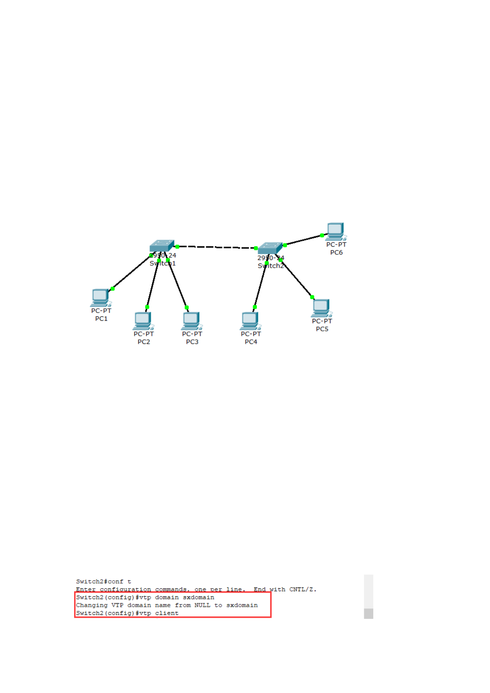
First of all, we plan the topology and test requirements of the network:
we use two switches, one of which is the core switch, and name it Switch1
and the other as Switch2. Choose 6 computers arbitrarily and name them
PC1~PC6. PC1 to PC3 are connected to Ethernet ports 1, 2, and 3 of
Switch1, and PC4 to PC6 are connected to Ethernet ports 1, 2, and 3 of
Switch2.
2. Draw the test topography
3. VLAN configuration process
1. First, configure the IP address and default gateway for workstation PC1-
PC6
PC1-PC6: from 192.168.1.1 to 192.168.1.6
2. Create a VTP domain and set the VTP operation mode
According to the different roles of the switch in the VTP domain, VTP
can be divided into three operation modes: server mode, client mode, and
transparent mode.
(1) Set Switch1 as a VTP server
(2) Set the VTP domain name to sxdomain
(3) On switch 2, set the VTP domain name and make it in VTP client mode
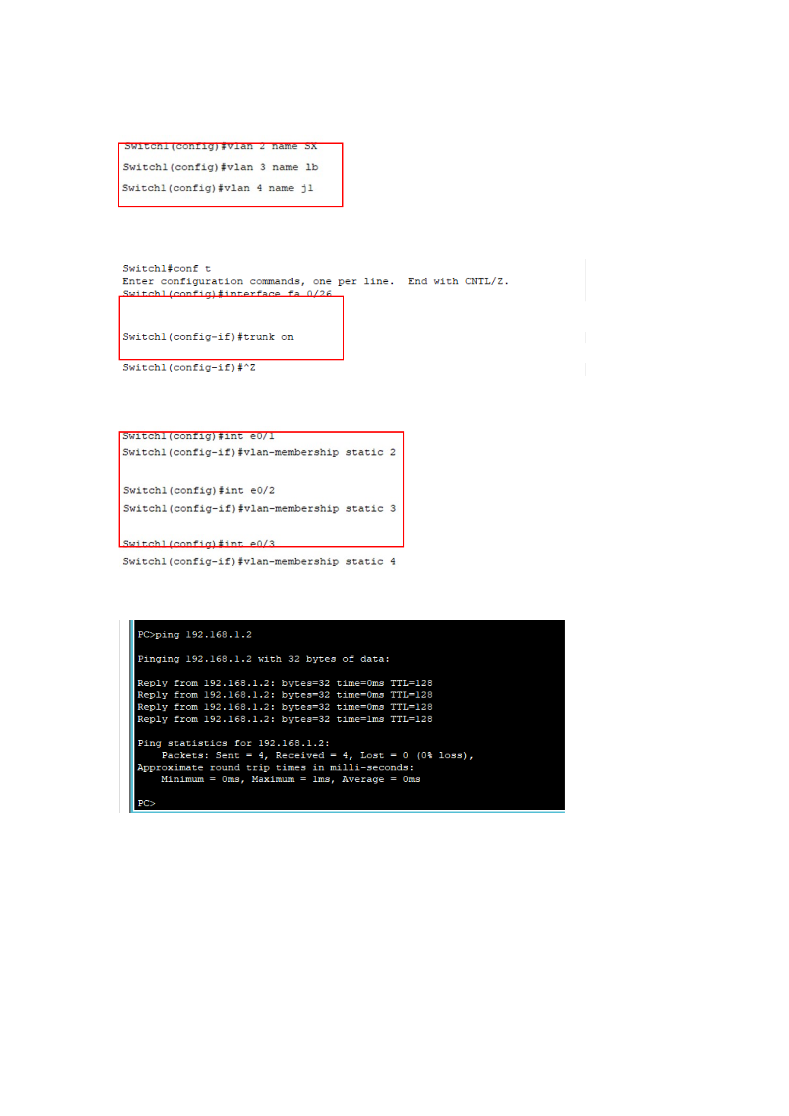
3. Create a VLAN
4. Configure the relay protocol and relay line
5. Divide switch ports into different VLANs (Switch1 and Switch2)
Test:
Experiment 2: Wireshark packet capture
First, the purpose of the experiment
1. Master the method of installing and configuring the network protocol
analyzer Wireshark;

2. Familiar with the basic methods of using Wireshark to analyze network
protocols.
Second, the content and requirements of the experiment
1. Install and configure the network protocol analyzer Wireshark
2. Use and be familiar with the interface environment of the Wireshark
analysis protocol (menus, toolbars, various windows, etc.).
3. Learn to use Wireshark to capture protocol packages.
3. Experimental procedures
1. Download and open Wireshark Network Analyzer:
2. Click the Capture-> option to open the Capture Interface page:
3. Click the start button, I select the interface with the IP address of
14.215.177.39, and the packet capture process will be started after
clicking the start button:
(1) To capture ARP packets, ICMP packets, and UDP datagrams, you can
run the ARP -D command in the CMD window to delete the current ARP
cache.
Use the TRACERT command to trace the path of the grouping from the
source point to the end point:
2) To capture TCP packets, you need to open Internet Explorer and visit a
WWW website.
Switch the window to Wireshark, and you can see that the packets of TCP,
UDP, ICMP, and ARP have been caught.
Catch the ARP packet:
Catch TCP packets:
Catch UDP packets:
Catch ICMP packets:
4. The following analysis of the packets, the environment for capturing the
packets is:
(1) My operating system is Windows 10, run the arp -a command to delete
the ARP cache to grab the ARP packet; :
(2) Capture ICMP packets;
(3) Capture ICMP packets;
(4) Open the website in a browser window to capture TCP packets. Click
the Stop button to complete the packet capture;
5. Analysis
(1) Click the row where the ARP request group is located in the window
and expand EthernetII below. Analyze the format of the MAC frame:
(2) Click the row where the ARP request group is located in the window to
analyze the captured ARP request group:
(3) Click the row where the ICMP packet is located to expand Internet
Protocol. Analyze IP Datagrams:
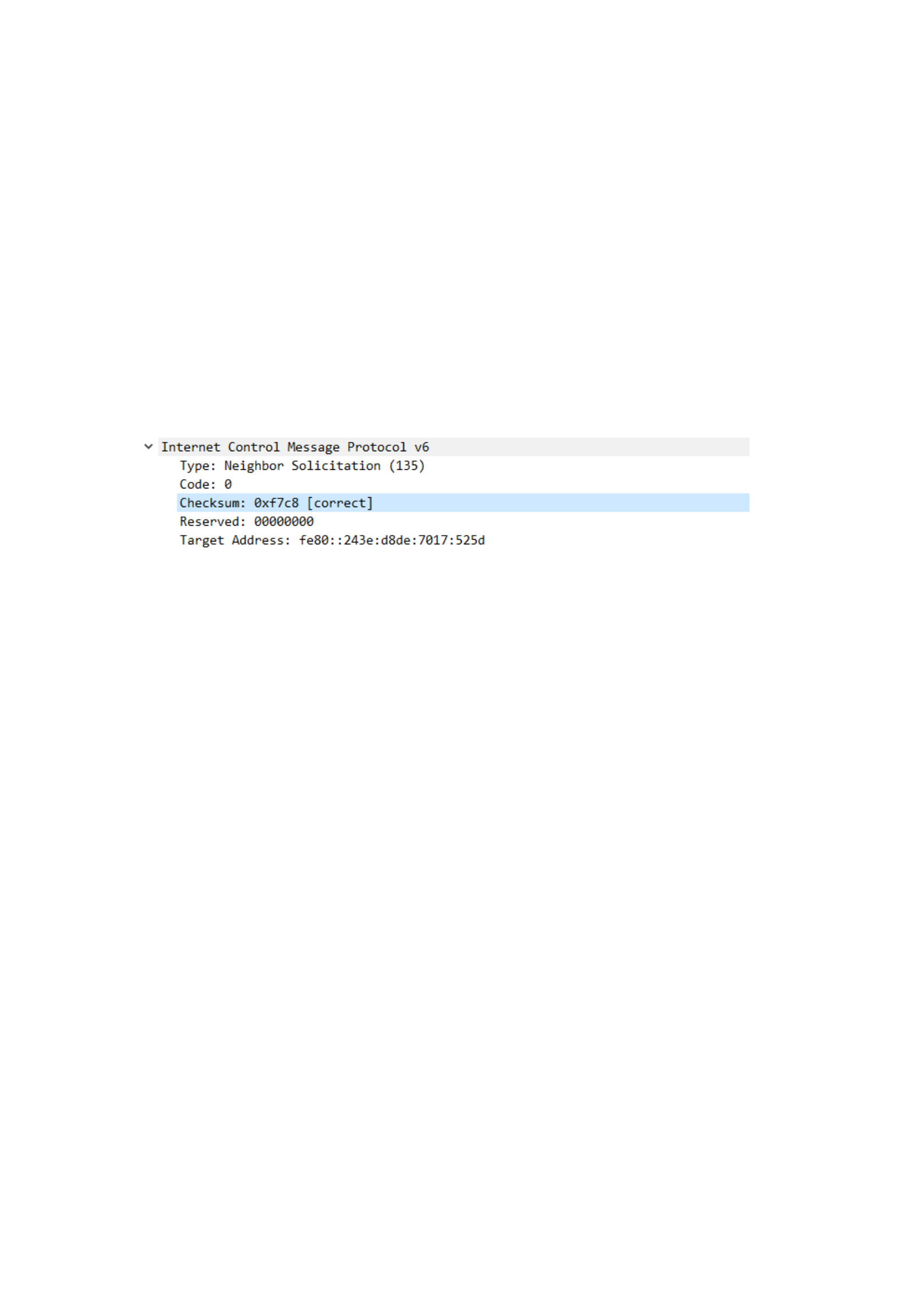
(4) Click the row where the ICMP packet is located to expand the Internet
Control Message Protocol to analyze the ICMP packet.
(5) Click on the row where the DNS protocol is located, expand the User
Datagram Protocol, and analyze the UDP datagram format:
(6) Click the line where the DNS protocol is located, expand the
Transmission Control Protocol, and analyze the format of the TCP packet
segment.
Experiment 3: Fabrication of twisted pairs
First, the purpose of the experiment
1. The skill of using network cable pliers to make twisted pairs
2. Be able to use network cables to test the correctness of twisted pair
jumpers.
3. Understand the composition structure of twisted pair and crystal head;
4. Understand the characteristics of network cable connection between
network devices.
2. Experimental equipment
1. A pair of RJ-45 crimping pliers
2. Several super 5 twisted pairs
3. A line tester
4. 2 crystal heads

3. Experimental procedures
(1) Task 1: Production of twisted pair straight line
The production process is divided into 4 steps, "peeling", "organizing",
"checking" and "pressing", and the specific operations are as follows:
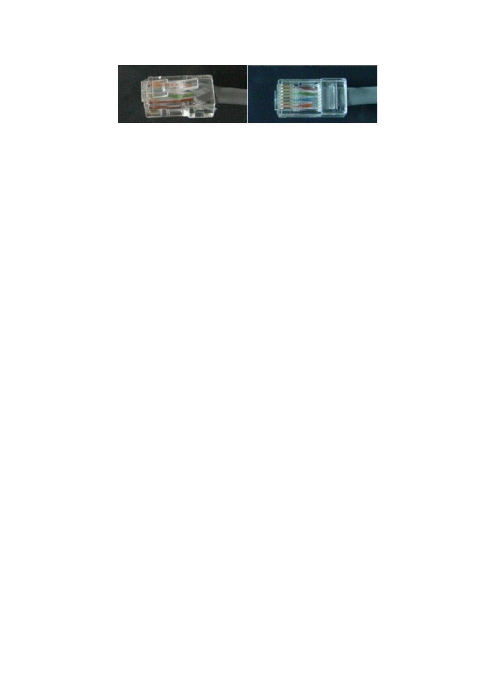
1. Prepare 5 types of twisted pair cables, RJ45 plugs and a special crimping
pliers, as shown in the figure:
2. Use the stripping knife edge of the crimping pliers to cut the outer
protective sleeve of the Category 5 wire (be careful not to cut the
insulation layer of the twisted pair wire inside), and the knife edge is at
least 2 cm away from the end of the Category 5 wire;
3. Peel off the cut outer protective sleeve (rotate and pump outward);
4. Expose 4 pairs of twisted pair cables in Category 5 cables;
5. Arrange the wires according to the EIA/TIA-568B standard and wire color
according to the specified serial number. (orange-white, white, white-
green, blue, white-blue, green, white-brown, brown);
6. Arrange the 8 wires in parallel flat and neatly, leaving no gaps between
the wires;
7. Prepare to cut 8 wires with the cutting edge of the crimping pliers;
8. Cut the cable. Be sure to cut it neatly, the length of the stripped wire
should not be too short (10mm-12mm), you can leave it longer first, do
not peel off the insulating outer layer of each wire;
9. Put the cut cable into the RJ-45 plug to try the length (to plug it into the
end), and the outer protective layer of the cable should finally be able to
be compacted in the recess in the RJ-45 plug and adjust it repeatedly;
10. After confirming that everything is correct (pay special attention not to
reverse the order of the wires), put the RJ-45 plug into the indenter slot of
the crimping pliers and prepare for the final compaction;
11. Hold the handle of the crimping pliers with both hands and press hard.
Note that after this step is completed, the 8 pin contacts of the plug pass
through the insulating outer layer of the wires and are tightly crimped
together with each of the 8 wires;
12. Done. Connect the network cable to the detection device, check
whether the corresponding indicator light will be on, if it is on, the twisted
pair cable is successfully made. If it is unsuccessful, it is necessary to
check whether there is any color error in the interface at both ends, and
secondly, check that the insertion is very clear.
(2) Task 2: The production of twisted pair crossings
The steps and operation essentials of making a crossing line are the
same as making a straight line, except that one section at both ends of
the crossing line is according to the EIA/TIA-568B standard , and the other
end is the EIA/TIA-568A standard;
(3) Jumper test
Once the twisted pair is made, the next step is to test its connectivity
to determine if there is a connection failure.
Cable testers are usually used for inspection. It is recommended to use
a specialized testing tool such as Fluke DSP4000, etc. for testing. It is also
possible to buy an inexpensive network cable tester. Such as the
commonly used Shanghai Sanbei "expert" network cable tester. As shown
in Fig. During the test, insert the crystal heads at both ends of the twisted
pair cable into the RJ-45 ports of the main tester and the remote test end
respectively, and turn the switch on
to "ON" (S is for slow gear), the main unit indicator flashes in order from 1
to 8. As shown in Fig.
If the connection is not normal, the following conditions are displayed:
① When one of the wires is broken, the lights of the corresponding wire
number of the main tester and the remote test end are not on.
② When there are several wires open, the corresponding wires are not lit,
and when there are less than 2 wires connected, the lights are not on.
③ When the network cables at both ends are out of order, the line
number of the remote test end connected to the main tester side is
illuminated.
④ When there are 2 short circuits in the wires, the main tester shows the
same and the remote test end shows the two wires that are short-
circuited. If there are more than 3 (including 3) wires short-circuited,
the lights corresponding to all short-circuited wires will not be on.
⑤ If there is a red light or yellow light, it means that there is a
phenomenon such as poor contact, at this time, it is best to press the
crystal head at both ends with crimping pliers once, and then test, if
the fault still exists, you have to check whether the order of the core
wire is correct. If the cores are in the wrong order, they should be
remade.
Experiment 4: Basic operation of the router
First, the purpose of the experiment
1. Understand how the router works
2. Master the basic operation of the router
2. Experimental procedures
1. Basic functions of the router command line
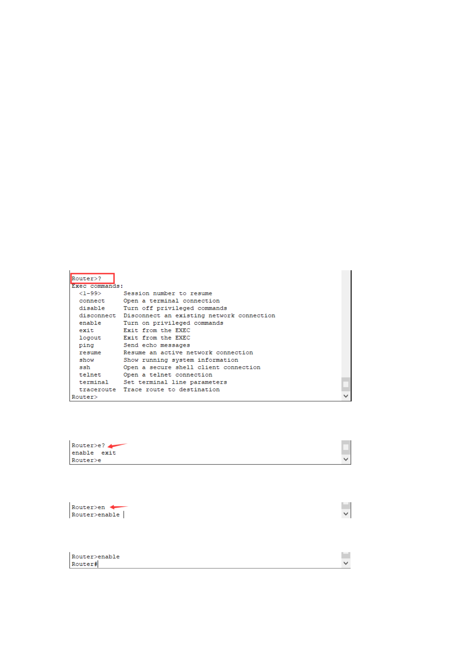
(1)ROUTER>? --- Displays all executable commands in the current
mode
(2)ROUTER>e? --- Displays all commands starting with e in the current
mode
(3) ROUTER>en<tab> --- Autocomplete command
(4) ROUTER> enable --- into privileged mode
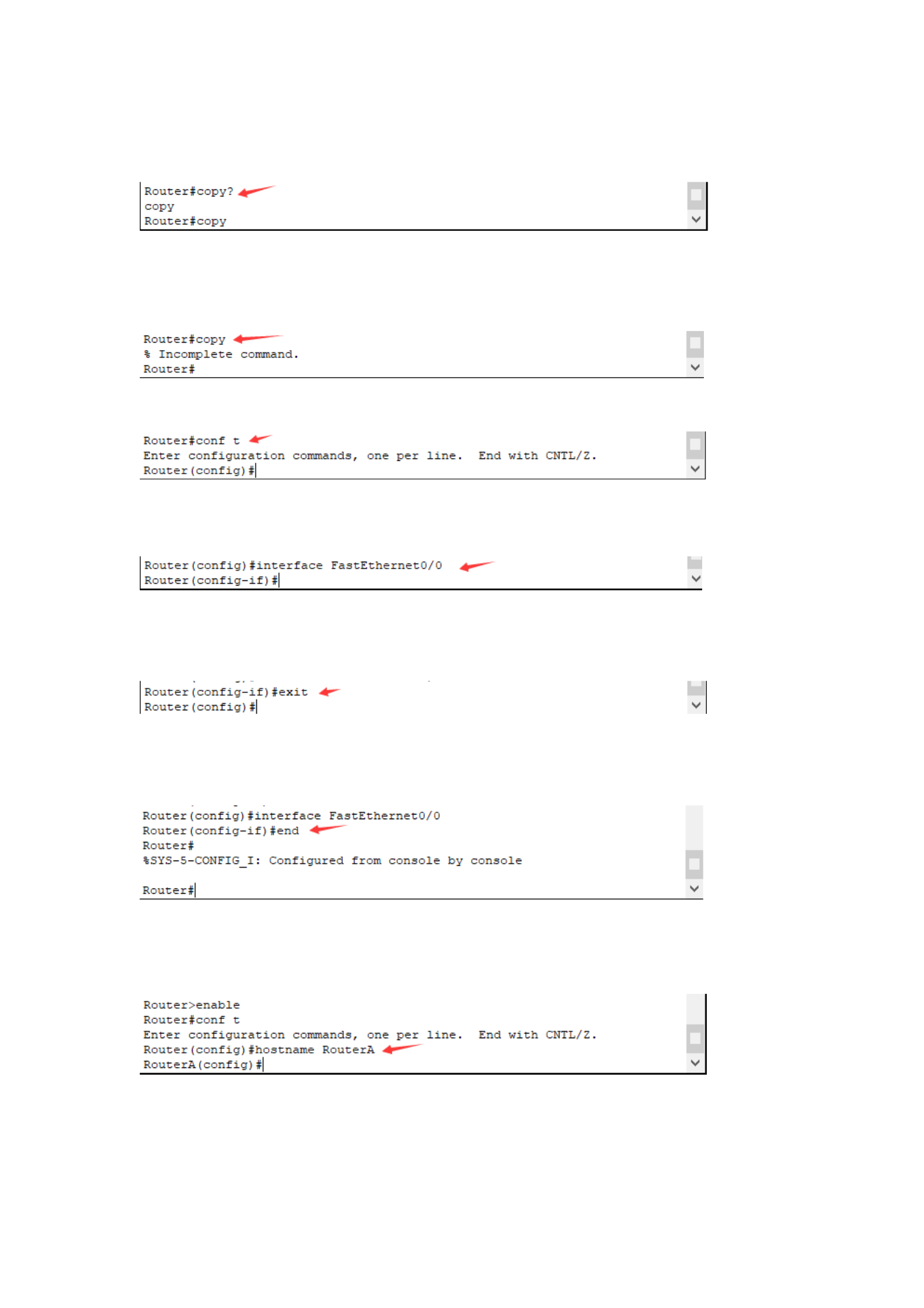
(5)ROUTER#copy ?--- Displays the parameters that can be executed
after the copy command
(6) ROUTER#copy --- The prompt command is not finished, and must be
accompanied by executable parameters
(7) ROUTER#conf t --- Enter the global configuration mode
(8) ROUTER(config)#interface fastEthemet 0/0 --- Enter the Router Port
Fa0/0 interface configuration mode
(9) ROUTER(config-if)#exit --- RETURN TO THE PREVIOUS OPERATION
MODE
(10) ROUTER(config)# interface FastEthernet0/0 --- Use end to return
privileged mode
2. Configure the name of the router
Set the router name to RouterA
3. Configure the interface of the router and check the interface
configuration
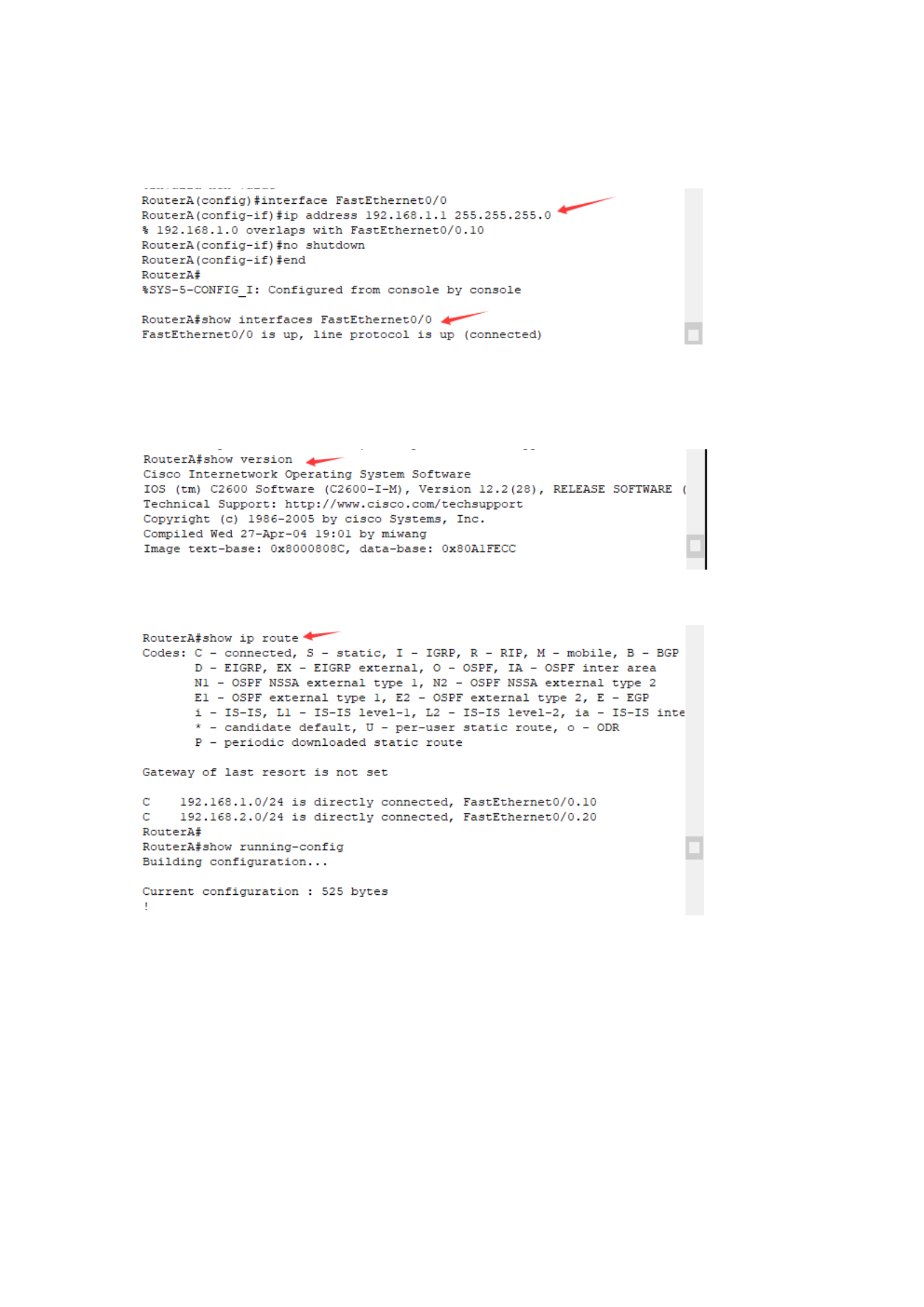
Enter the Fa0/0 interface configuration mode, configure the interface IP
address, and enable the port
4. Check the configuration information of the router
(1) Check the version information of the router
(2) Check the router information
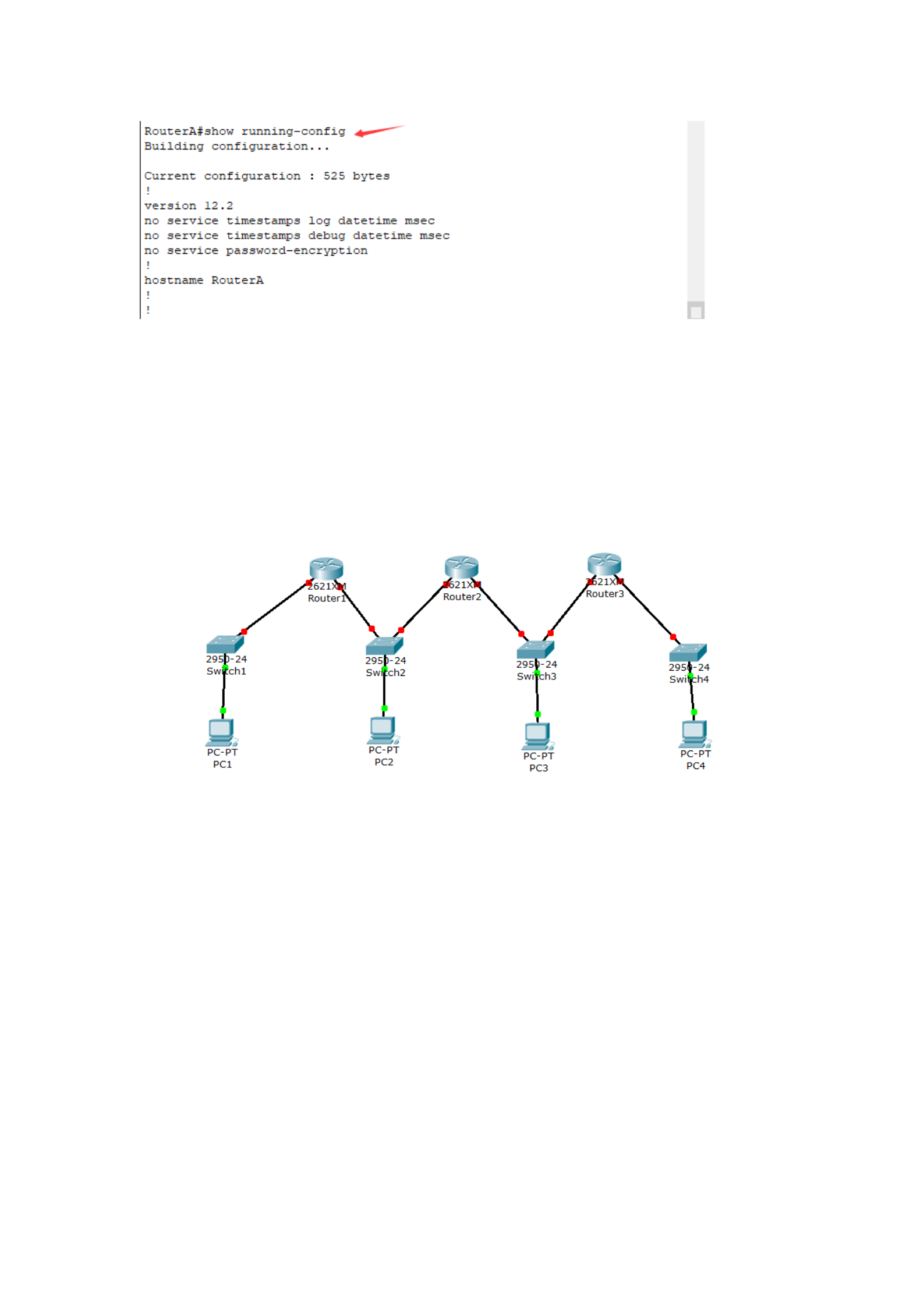
(3) Check the current configuration information of the router
Experiment 5: Static Routes
1. Experimental procedures
1. First, the initial connection is as follows: Router1 is connected to
Switch1 and Switch2, Router2 is connected to Switch3 and Switch3,
Router3 is connected to Switch3 and Switch4, and secondly, the switch is
connected to the PC respectively;
2. Then configure and enable the IP address of the port of Router1.
3. Configure and enable the IP address of the port of Router2.
4. Configure and enable the IP address of the port of Router3.
5. Next, configure the IP addresses and default gateways of PC1, PC2, PC3,
and PC4 respectively;
6. At this time, the test is carried out, and it is obvious that PC2 to PC1 is
not passable, PC3 to PC3 is not passable, and PC4 to PC3 is not passable;
7. At this time, configure the route, first configure Router1;
8. Configure Router2 as well.
9. Check the routing table of Router2 at this time.
10. And test PC2 to PC1, PC1 to PC3 are connected, and PC1 to PC4 are
not connected;
14. Configure Router3 at this time;
14. View the routing tables of 3 routers;
15. Test: Conduct a test on PC1 and find that it is compatible with PC2, PC3
and PC4;
16. Final topology diagram
Experiment 6: Basic configuration of the switch
First, the purpose of the experiment
1. The working principle of the palm switch.
2. Understand the startup process of the switch.
3. Use the HyperTerminal program on the Windows operating system to
configure the transducer through the console port of the switch.
4. Be familiar with and master the basic configuration of the switch, such
as IP address, host name, password, etc.
5. Master the configuration and viewing methods of static MAC addresses.
6. Be familiar with and master the port configuration of the switch and
view the port information.
Second, the experimental environment
Cisco Packet Tracer software
3. Experimental procedures
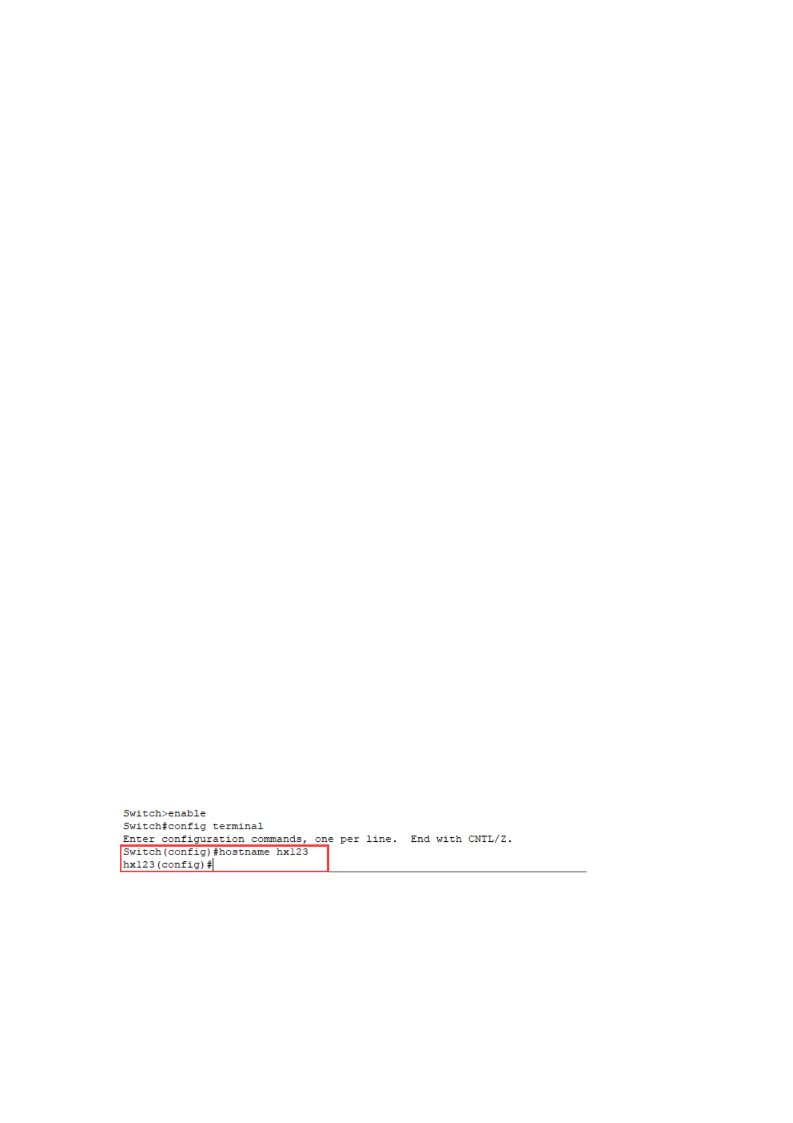
1. Set the hostname
In global configuration mode, the host name of the switch is set to HX123,
and the configuration command is as follows:
2. Configure the management IP address
(1) Set or modify the management IP address
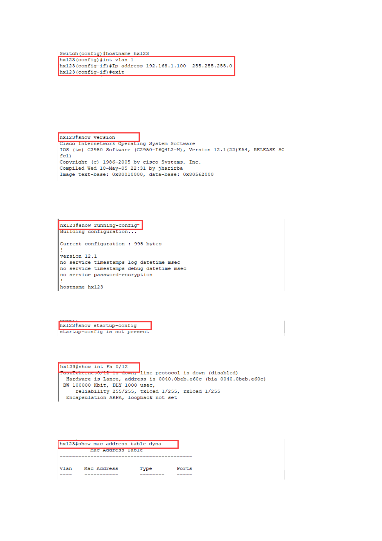
(2) Cancel the management IP address: no IP address
3. View the switch information
(1) Check the IOS version
(2) View the configuration information
(1) Displays the configuration that is currently running
(2) Display the boot configuration saved in the NVRAM
(3) Check the port information
(4) Display the exchange table information
(1) View the MAC address table of the switch
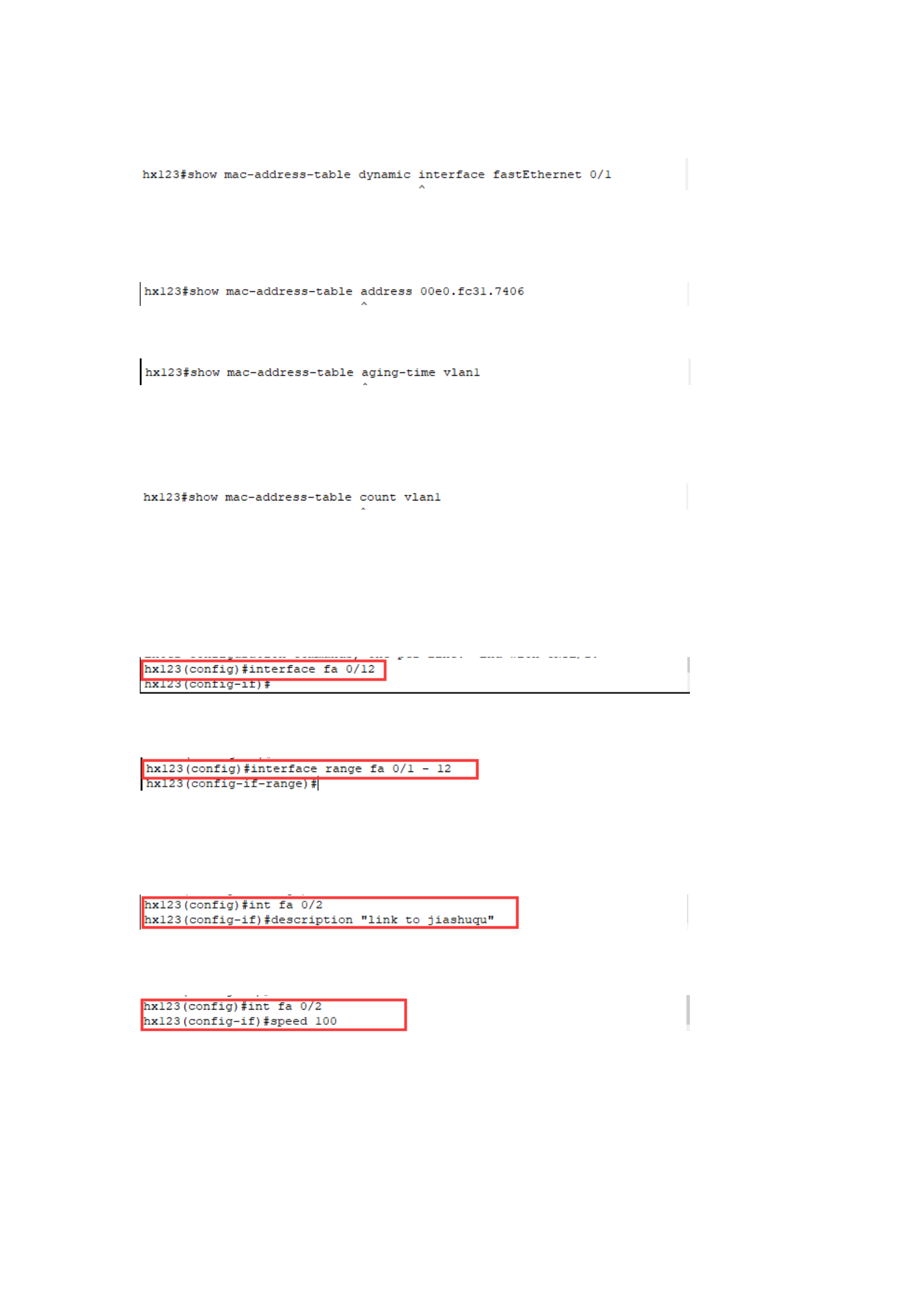
(2) Check the MAC address learned from a certain port
(3) Displays the port and VLAN information associated with a MAC
address
(4) Check the aging time of the exchange table
(5) Check the number of addresses in the exchange table and the size of
the exchange table
4. Configure the Layer 2 switch port
(1) Port selection
(1) Select a port
(2) Select multiple ports
(2) Configure the Ethernet port
(1) Give the port a descriptive name
(2) Set the port communication speed: speed[10|100|1000 | auto]
(3) Set the single-duplex mode of the port: half | full | auto
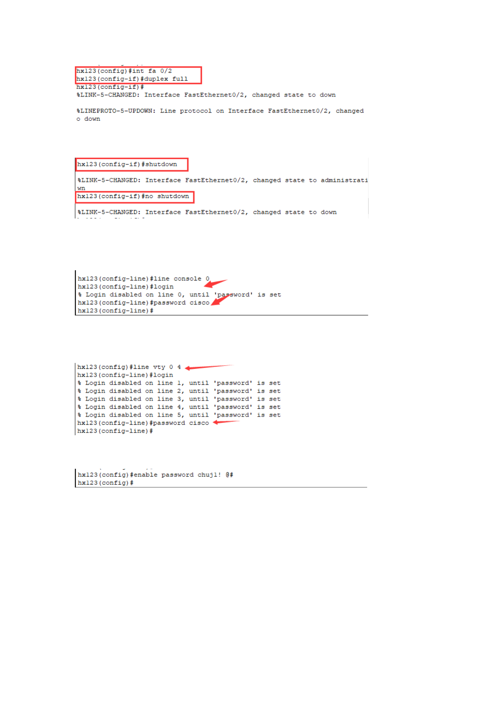
(4) Enable or disable the port
5. Configure a password
(1) Create a terminal console access password: line console 0
(2) Password protection when establishing Talnet session access: line vty 0
4
(3) Restrict access to privileged EXEC mode: enable password
Experiment 7: Dynamic routing
1. Experimental procedures
1. First, the initial connection is as follows, so that Router1 is connected to
Switch1 and Switch2, Switch1 is connected to PC1 and PC2, and Switch2 is
connected to PC3 and PC4.
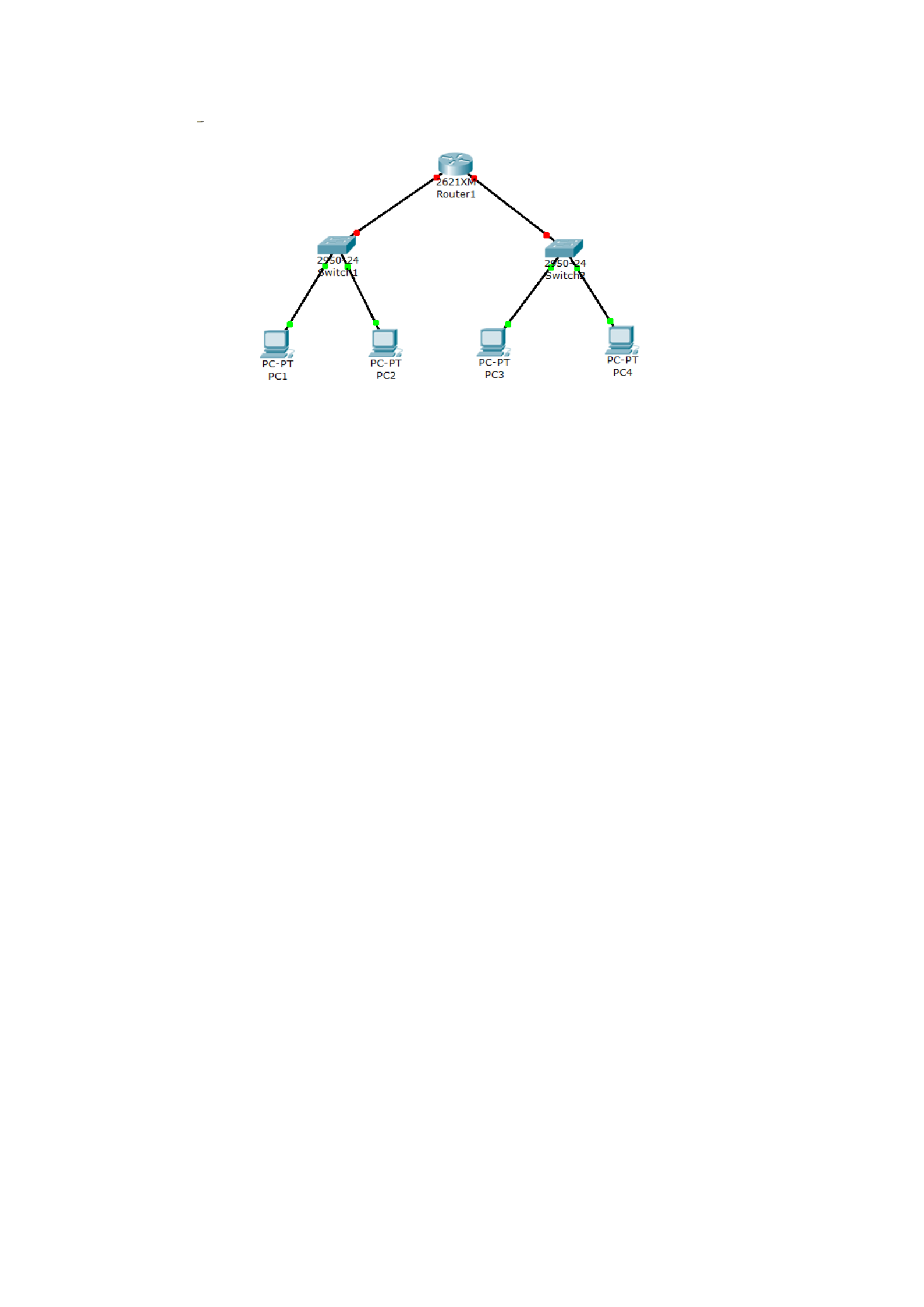
2. Next, configure the router, configure the IP addresses of ports 0/1 and
0/2 and enable ports;
3. Next, configure the IP address and default gateway for PC1 and PC2;
3. Then configure the IP address and default gateway for PC3 and PC4;
4. Test: Test PC1 and find that PC1 and PC2, PC3 and PC4 are all
connected;
5. View: Check the router routing table, indicating that the IP address is
currently connected to 1.0/2.0;
6. Add 2 routers, 2 switches, and 2 PCs, and the topology diagram after
adding is as follows;
7. Configure IP addresses for the 0/0 and 0/1 interfaces of Router2 and
enable them.
8. Configure and enable IP addresses for 0/0 and 0/1 interfaces of Router3.
9. Configure IP address and default gateway for PC5 and PC6;
10. Test PC5 and find that PC5 and PC1 are not connected, and the default
gateway 3.254/1.253 is connected;
11. Next, configure a static route for Router2 and view the routing table.
12. Configure static routes for Router1 and view the routing table.
13. Test PC5 and find that PC5 is connected with PC1 and PC2, but not with
PC6;
13. Next, configure a static route for Router3 and view the routing table.
14. Test: Test PC5 and find that PC5 and PC6 are also connected;
Experiment 8: Single-arm routing
First, the purpose of the experiment
The single-arm routing function of the router is used to implement inter-
VLAN routing
2. Experimental procedures
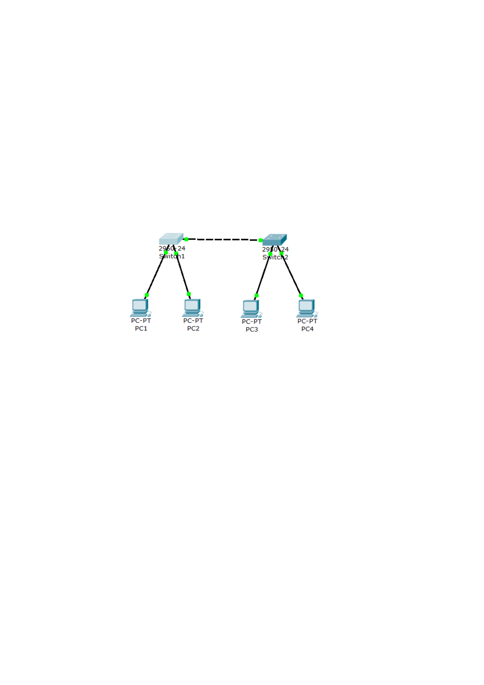
1. The experimental topology diagram is as follows, place 2 switches and 4
PCs, connect Switch1 to PC1 and PC2, connect Switch2 to PC3 and PC4,
and then connect Switch1 and Switch2:
2. Configure VLANs for Switch1 and add vlan1 and vlan2
3. Configure VLANs for Switch2 and add vlan1 and vlan2 as for Switch1
4. Port 0/1 of Switch1 is assigned to vlan10, and port 0/2 is assigned to
vlan20
4. Port 0/1 of Switch2 is assigned to vlan10, and port 0/2 is assigned to
vlan20
5. Change the 0/3 port mode of Switch1 to Trunk, and only allow
vlan1/10/20 to pass through:
6. Change the 0/3 port mode of Switch2 to Trunk:
7. Configure IP addresses for PC1 and PC3 so that they belong to the same
network segment;
8. Configure IP addresses for PC2 and PC4 so that they belong to the same
network segment;
9. Test PC1, it can be found that PC1 and PC3 are connected, and PC2 and
PC4 are not connected, and PC2 is the same;
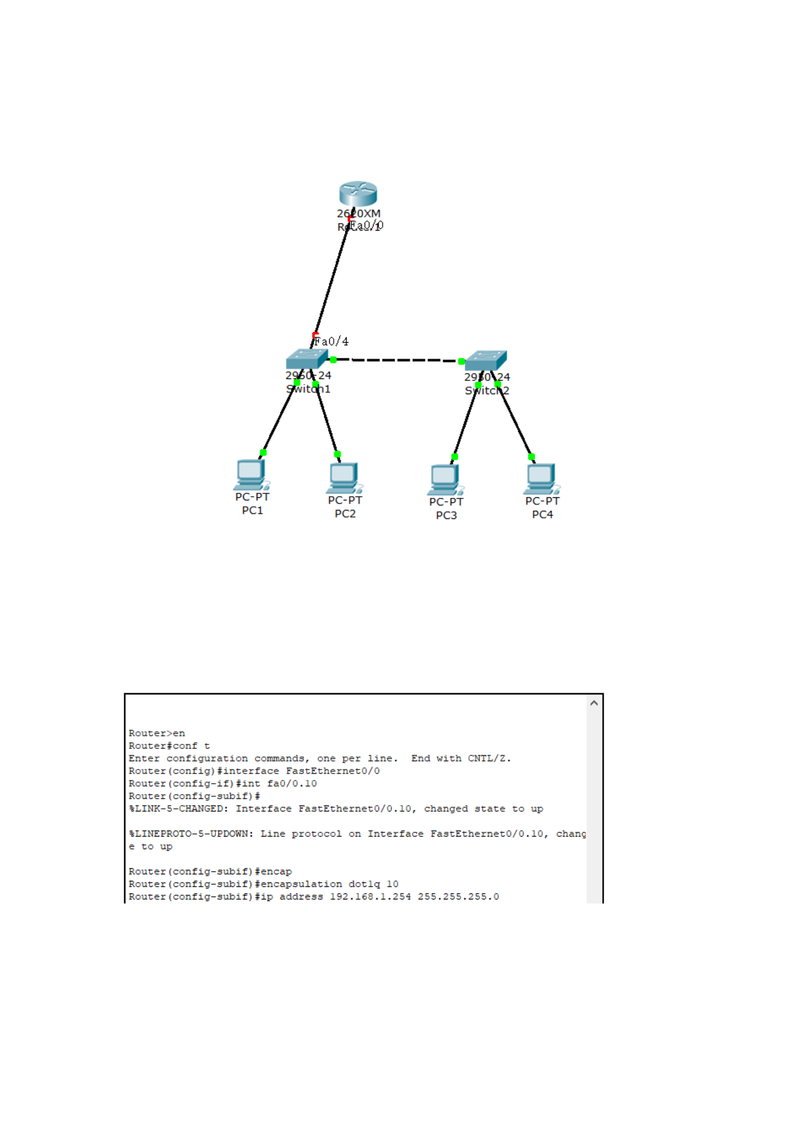
10. Add a router and connect it to port 4 of Switch1.
11. Change port 0/4 of Switch1 to trunk mode.
12. Configure the interface for the router
13. Create a logical sub-interface, configure the sub-interface, encapsulate
the protocol, and assign the sub-interface to VLAN10:
14. Create another sub-interface and configure it
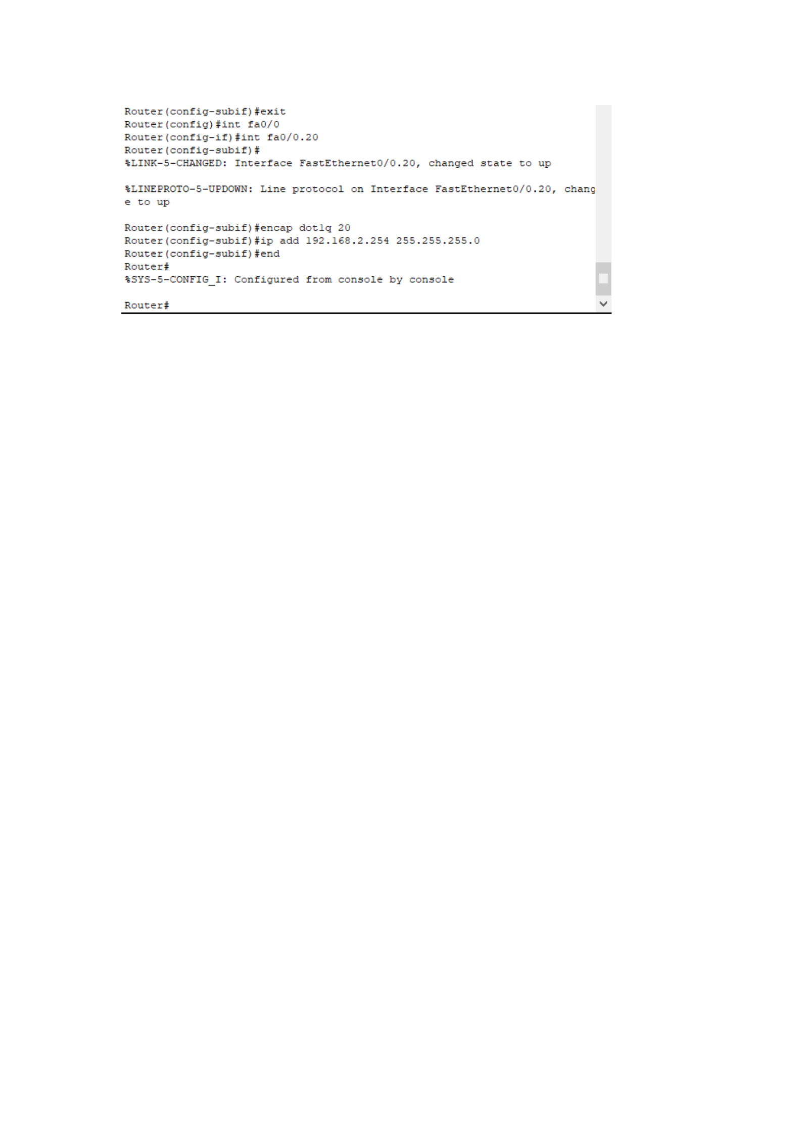
15. Test: Open the Switch1 command line and check the vlan
16. Test: Open the router command line: check the IP

17. Configure the default gateway for PC1 and PC3
18. Configure the default gateway for PC2 and PC4
19. Test: Test PC1, and it can be found that PC1 and PC3, PC2, and PC4 are
all connected;

