


1
DESIGN AND STRUCTURAL ANALYSIS OF A STEEL WORKING
PLATFORM FOR A FACTORY BUILDING
Student name
Course code
Institution
Instructor
Due date

2
DESIGN AND STRUCTURAL ANALYSIS OF A STEEL WORKING
PLATFORM FOR A FACTORY BUILDING
ABSTRACT
This paper includes the detailed working platform design for factory building
construction and analysis of structures using steel. The implemented design was done as per the
condition laid down for the Sixth Group pertaining to the material selection layout design details
of structure calculations and construction drawings. The purpose is to guarantee there is reliable
support for the platform, as well as to conform to some of the standard construction codes (Jaskó
et al.,2020). Information on the material selection criteria or determinations, load analysis, stress
analysis, construction drawings and nodes and connecting points are also presented in the report.
Even though the working platform is not the most complex component of a building, the research
results and the proposed design solution are meant to offer a stable and optimized model for its
construction.

3
INTRODUCTION
The purpose of this task is to develop a working platform for steel structures for factory
construction in the countryside according to the requirements set for the sixth group. This design
project of the slim-line working platform aims to guarantee that the working platform is
structurally sound and safe with the adherence to a well-documented process that begins with the
selection of materials, followed by the structural layout design and the detailed calculations done
with the help of computer software, and ends with the fabrication of precise construction
drawings to be used in construction. This involves making the right choices with respect to the
materials that will be used in construction with particular reference to load and elevation
requirements, developing an effective network of beams, columns, and supports, and ensuring
through what involves complex calculations that the structure is safe and meets all the
requirements as set out in the building codes. Furthermore, the corrosion studies will consist of
state-of-the-art construction drawings, including construction drawings of structural layout,
processing details of main beams/columns, and the elaborate nodes of all the structures De
(Domenico et al.,2021). Thus, the key components developed in the course of the project
contribute to creating rational, effective, and safe design features of the working steel structure
platform for a factory building while taking into account its peculiar context.
MATERIAL SELECTION
Material selection aims to select suitable materials that can be used for the fabrication of
beams, columns and support structures for the assembly in order to withstand various loads and
bear design loads. This also means that the materials have to be chosen according to several
criteria, such as selecting steel grades for loads and elevations, or how demands for durability are
met by selection of resistance, first of all to corrosion, and getting that, the selection of high
availability materials while keeping low costs is crucial. In the selection process, refer to the
general structural steel like ASTM A36 and ASTM A992, also known as the T-iron. ASTM A36
is liked due to its relatively high weldability, good machinability, and a minimum yield strength
of 25000 psi, so it has its use in the production of parts where high machinability and moderate
strengths are required. On the other side, due to higher yield passing of 50,000 psi and excellent

4
toughness, the ASTM A 992 is preferred for primary frame elements such as the main beam and
column in structures as well as members that require high strength and toughness for performing
dynamic loads and other unfavorable circumstances. The assessment of the characteristics of the
material, which includes yield strength, tensile strength, weldability, machinability, and
durability, determined the rationale used for choosing the material (Wagri et al.,2022). Secondary
framing members and lateral supports: ASTM A36 is most suitable for this purpose since it is
relatively cheap compared to other grades, whereas primary members: ASTM A992 is preferable
to use here since it offers the most efficient structure for the contemporary building codes. It is a
'perfect playing field,' so to speak, as this comprehensive selection enables the construction of a
secure, robust, durably effective, and cost-efficient working platform of a steel structure that can
meet the load-bearing and elevation standards set above as well as synchronously relevant
standards.
STRUCTURAL LAYOUT DESIGN
Objective
In this aspect, the objective is to propose the plan for where beams, columns, and
supports will be placed, whereby they should be well placed in an attempt to achieve stability
and proper dissemination of Load across the framework.
______
Layout Plan
i. Beam Layout: Positioning and designing types of beams are critical as they
support the platform's Load. Primary beams will be arranged in the direction of the longer side of
the platform, measuring 36 meters, while secondary beams will be aligned in the direction of the
shorter side, measuring 12 meters. The spacing of the beams will play a crucial role in the design
and will depend on the weight that will be placed on them, as well as the strength of the
structure.
ii. Column Layout: The columns are to be arranged at certain areas where the
beams are fixed to help in the sharing of loads to the foundation area. Columns will be installed
at sufficient intervals to spread the loads evenly and also to reduce the possible bending moment

5
for a beam. The placing will take into consideration procedural access and utilization of the
platform.
iii. Support Layout: For further reinforcement, additional materials – braces, ties,
etc – will be added to ensure the stability of the chosen structure. These supports will join the
beams to columns and enable the structures to offer more rigidity against sway and buckling as a
result of laden loads.
______
Design Considerations
i. Load Distribution: The layout will call for balanced loads where the tendency is
geared towards sharing the Load between beams and columns with less stress being focused on
any individual part of the structure, thus increasing the general strength of the structure.
Precarious loads that are to be placed on it, such as personnel and equipment, will also be
considered apart from the self-weight of the platform.
ii. Structural Stability: Durability will be addressed due to the choice of supports,
which will take into account stabilizing possibilities of the structure and potential dynamic
effects like vibrations or wind loads. This walking assist is going to be supported by bracing and
some of the lateral support systems as and when required.
iii. Compliance with Safety Standards and Regulations: This will involve the
observation of legal requirements and the act of ensuring that the completion structure does not
contravene the law or any code of desirable architectural construction (Hills & Schleicher,2020).
This encompasses ensuring that the structure conforms to standard requirements for load rating
and types of materials to be used, as well as recommended construction methods.
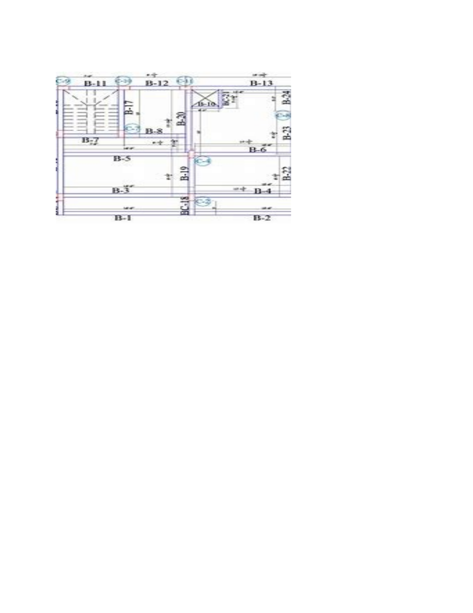
Diagram: Structural Layout Drawing
To further help the reader understand the structural layout, a conceptual layout of beams,
columns, and supports is depicted below. This diagram is intended to be simplified and should be
6
expanded through translation with further details of dimensions and location in the design stage.
STRUCTURAL DESIGN AND CALCULATIONS
Objective
Assess structural calculations for the so-called 'soundness' of the design work.
Load Calculation
Dead Load: The permanent static Load is the weight of beam-columns and supports
along with all the appurtenant structures that are permanently in the building.
Dead Load (DL)=weight of the beams, weight of columns + weight of supports
Thus, for simplicity, let us assume that the weight per square meter of the platform is the
same. For a steel structure, the value is chosen as 25 kN/m² (this includes the structure's weight).
Total Dead Load = multiplied by the area of the platform to the uniform weight
distribution on it.
Platform area=36m×12m=432m2
Total Dead Load=432m2×25kN/m2=10,800kN
Live Load: The variable Load includes the operational loads, such as personnel,
equipment, and any other movable loads. For this design, the uniform Load is given as Q1=12
kN/m2
TotalFLiveFLoad=PlatformFarea×Q1

7
TotalFLiveFLoad=432m2×12kN/m2=5,184kN
Stress Analysis
perform stress analysis for beams and columns, calculating bending moments, shear
forces, and axial forces.
i. Beams:
For a supported beam with a uniform load, the maximum bending moment M max_and
shear force Vmax can be calculated using standard formulas:
Mmax=ωL2
8
VMAX=
WL
2
Where:
w = uniform Load per unit length (kN/m)
L= span length of the beam (m)
Assume a primary beam span of 12 meters and a secondary beam span of 6 meters:
For primary beams (L=12 mL :
W primary=12kN/m+
25 kN ℑ2x12 M
2
=162kN/m
M max,Fprimary =
162kN ℑx
(
12 m
)
2
8
=2,916kN⋅m
Vmax,Fprimary=
162kN ℑx12
2
=972kN
For secondary beams (L=6 mL
W secondary=12kN/m +
25 kN ∕ m2×62
2=87 kN /m
M max,Fsecondary=
87 KN ℑx
(
6M
)
2
8
=391.5kN⋅m
Vmax,Fsecondary=
87 kN /m ×6M
2
= 261kN
ii. Columns:
The axial force (P) in each column can be estimated by dividing the total Load by the
number of columns. Assuming there are 12 columns (three rows and four columns per row):

8
P=Total dead loads+Totallive loads
Number of columns
P=
10800 kN +5184 kN
12
= 1,328kN
CONSTRUCTION DRAWINGS
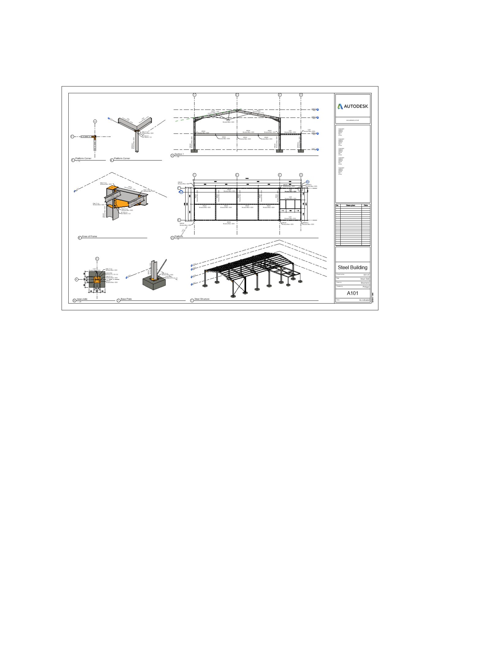
Drawing List
9
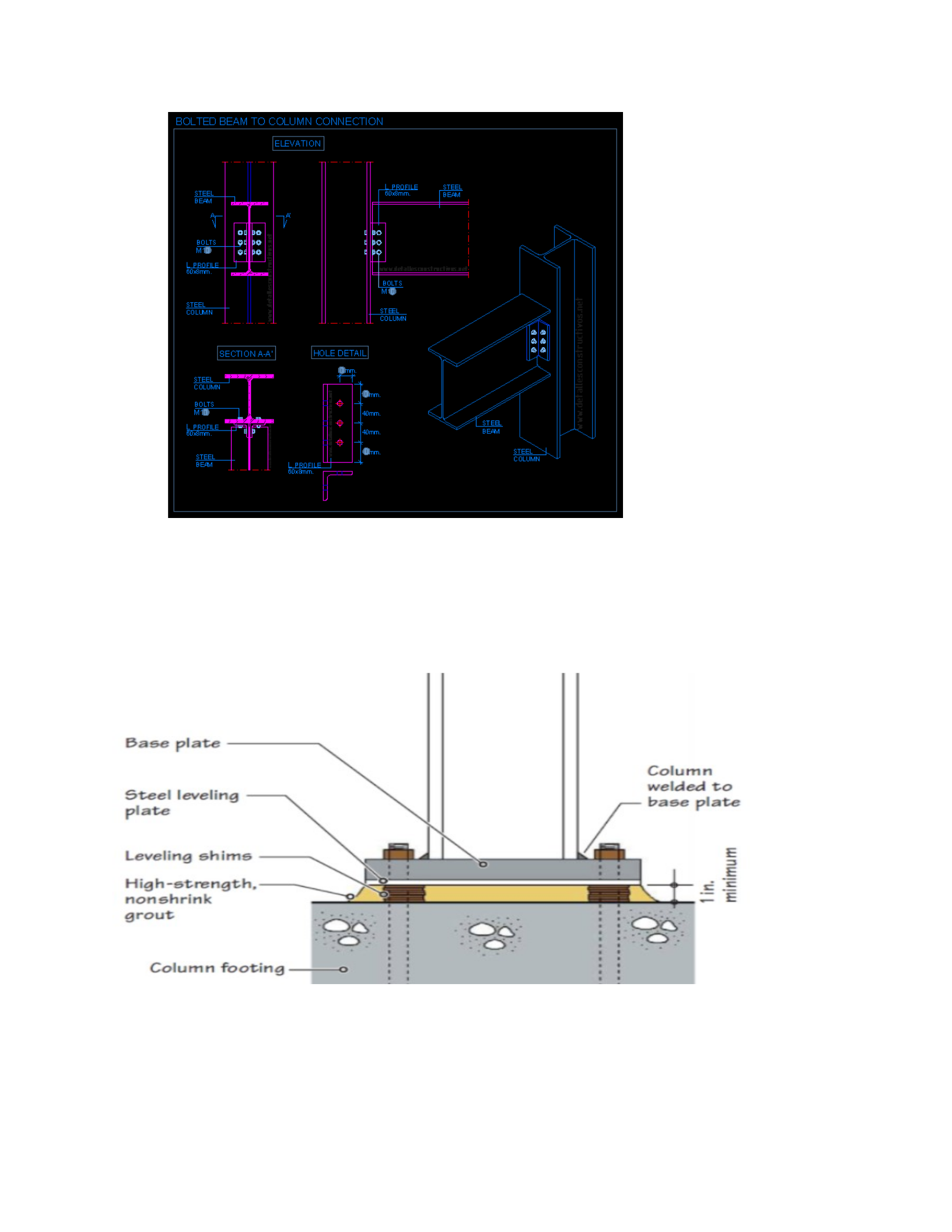
Main Beam Processing Drawing
10
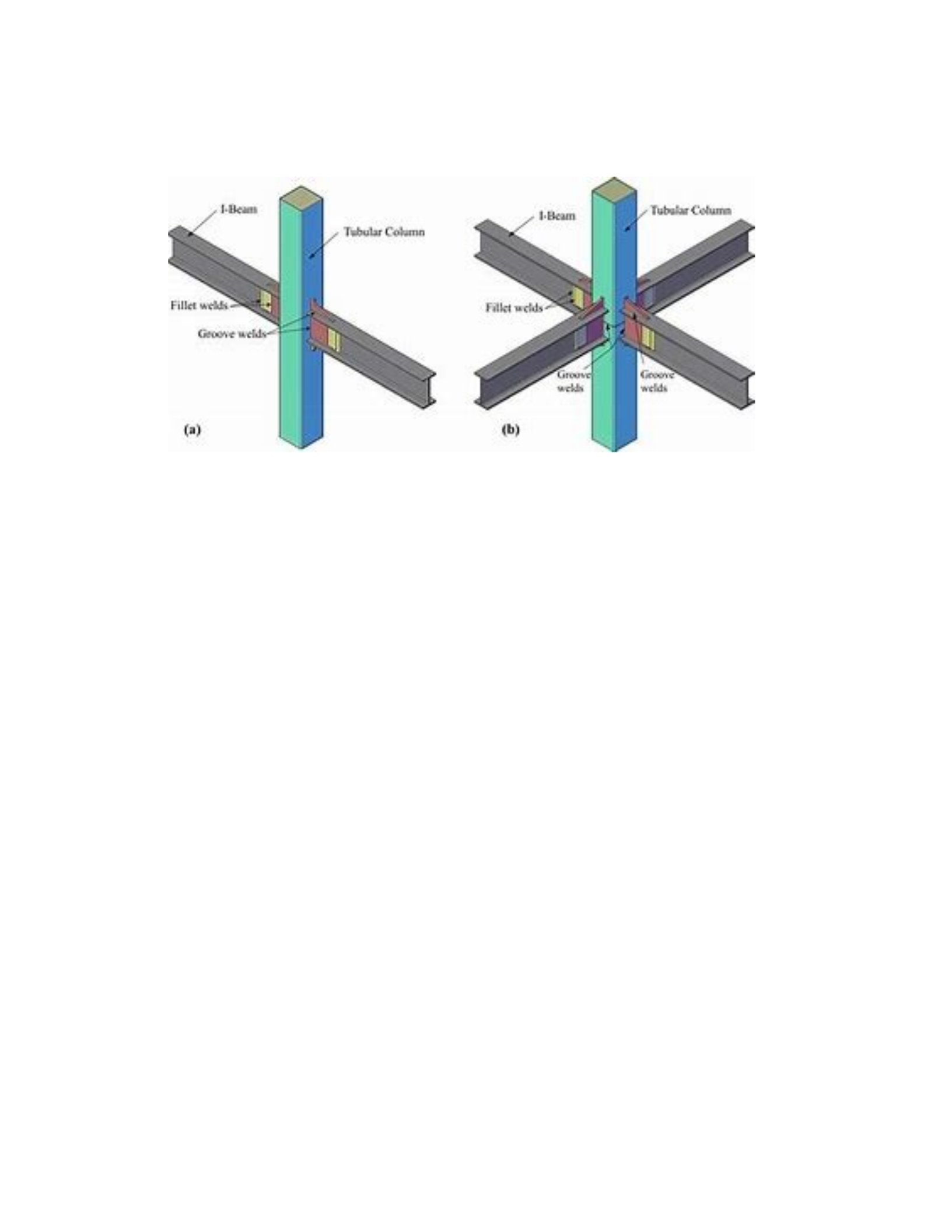
Column Processing Drawing:
11
NODE DETAILS:
CONCLUSION
Therefore, this project completed the goal set by drawing a steel structure working
platform of a factory building, meeting the six conditions mentioned above regarding the Sixth
group. With an organized procedure that entails the selection of appropriate materials, design of
the structure’s layout, and calculations done on the structural and construction drawings, this
design is sound, safe and conforms to the current code provisions. The choice of materials
pointed to the need to use the most appropriate, long-lasting and cheap materials, while the
design and computation of the structure provided the right loading and stability of the structure
(Nurazzi et al.,2021). The construction drawings further elaborate on the structural and aesthetic
design; therefore, they help in the actual fabrication and assembly of the structure. It goes
without saying that this project fully covers the present need for the working platform and, at the
same time, creates the kind of foundation that can be used in consecutive design projects in
similar situations. The concept could also be expanded beyond paper to look at other materials
for the platform and other possible optimizations for the platform.

12
REFERENCES
Jaskó, S., Skrop, A., Holczinger, T., Chován, T., & Abonyi, J. (2020). Development of
manufacturing execution systems in accordance with Industry 4.0 requirements: A review
of standard-and ontology-based methodologies and tools.FComputers in industry,F123,
103300.
De Domenico, D., Messina, D., & Recupero, A. (2021). A combined experimental-numerical
framework for assessing the load-bearing capacity of existing PC bridge decks
accounting for corrosion of prestressing strands.FMaterials,F14(17), 4914.
Wagri, N. K., Petare, A., Agrawal, A., Rai, R., Malviya, R., Dohare, S., & Kishore, K. (2022). An
overview of the machinability of alloy steel.FMaterials Today: Proceedings,Fpp. 62,
3771–3781.
Hills Jr, R. M., & Schleicher, D. (2020). Building coalitions out of thin air: Transferable
development rights and “Constituency Effects” in land Use Law.FJournal of Legal
Analysis,F12, 79-135.
Maksoud, A., Hussien, A., Mushtaha, E., & Alawneh, S. I. A. R. (2023). Computational design
and virtual reality tools are effective approaches for designing optimization,
enhancement, and validation of Islamic parametric elevation.FBuildings,F13(5), 1204.
Nurazzi, N. M., Asyraf, M. R. M., Fatimah Athiyah, S., Shazleen, S. S., Rafiqah, S. A.,
Harussani, M. M., ... & Khalina, A. (2021). A review of the mechanical performance of
hybrid natural fiber polymer composites for structural applications. Polymers,F13(13),
2170.

