

Semiconductors and Diode Theory
 jav284
Construct the circuit shown in Figure 1 below in Multisim with R1 = 2.2 KΩ and R2 = 1.8 KΩ. Use a 10% tolerance for the resistors. Assume an ideal diode.
Part (A)
- Calculate current (i) for the circuit. Show work.
- Calculate the voltage drops across R1 and across R2.
- Measure total current for the circuit and compare it to your calculated value in step 1. Be sure to provide a screenshot displaying the measured result.
- Measure the voltage drops across R1 and across R2, and compare it to what you calculated in step 2. Include a screenshot.
Part (B)
Reverse the polarity of the diode and construct the circuit. Repeat steps 3 and 4 above.
- Tabulate all your data, both calculated and measured, using units and headings as appropriate.
- Explain differences, if any, between your calculated and measured results in Part A. In detail and in words, explain the differences in results for Part B in relation to Part A.
Create a professional document including all the information above. Save the document as Lab1YourGID.docx (ex: Lab1G00050331.docx), or in another relevant document format.
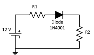
Figure 1
 11 years ago
 20
20
Answer(2)![blurred-text]()
![blurred-text]()

Purchase the answer to view it

 lab_1.docx

Purchase the answer to view it
NOT RATED
- semiconductors_and_diode_theory_lab1.docx
other Questions(10)
- POST FOR HANDSHAKE
- Finished
- Programming technical paper
- Acc 202 Principles of Managerial Accounting
- ECO 550 Week 10 - Check Your Understanding Ch. 17 Problems 1, 5, and 9(c) (All Questions Answered)
- Managers' encouragement of employee voice can lift well-being and productivity. Discuss.
- The Human Body
- Pricing please. NO PLAGARISM
- com-231
- Ethics and Philosophy