

Petrie’s Electronics Case Questions Solutions Chapter 7
 katlee2
| Petrie’s Electronics Case Questions Solutions (Chapter 7) | Points |
|---|---|
attachments mentioned in the questions are attached but I have already completed the diagram and only need answers to the specific questions listed below. the diagram is attached as diagramver2
COMPLETED IN THE ATTACHED DIAGRAM
Again, review the DFDs you developed for the Petrie's Electronics case. (I have placed the 3 level 1 diagrams in the Project Workbook - Week 3 folder in doc sharing, use your homework solution is attached, week 3 figure 6-2 visio document for the Record Customer Activities level 1) .
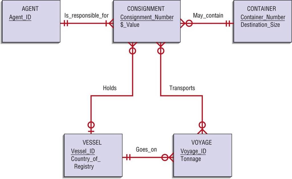
SEE THE ATTACHED DIAGRAMVER2 then Write an unambiguous definition for each attribute. Then, redraw PE Figure 7-1 by placing the six (and additional) entities in this case on the diagram along with their associated attributes.
need the following completed for this assignment: | 5 |
| 3. Using your answer to Question 2, designate which attribute or attributes form the identifier for each entity type. Explain why you chose each identifier. Look at page 199 for the definition of an identifier – an attribute that will make each entity unique (sometimes called candidates Key or primary keys; ie student ID etc). Pick an identifier for each of the six entities that will make them unique. Identifiers are underlined in attribute list in entities – so look on pages 200-201 for some examples) | 5 |
| 4. Using your answer to Question 3, draw the relationships between entity types needed by the system. Remember, a relationship is needed only if the system wants data about associated entity instances. Give a meaningful name to each relationship. Specify cardinalities for each relationship and explain how you decided on each minimum and maximum cardinality on each end of each relationship. State any assumptions you made if the Petrie's Electronics cases you have read so far and the answers to questions in these cases do not provide the evidence to justify the cardinalities you choose. Redraw your final E-R diagram in Microsoft Visio. Use the DFD on page 187, then add the relationships like in figures 7-20 and 7-21 on page 223. Example is promotion_is_earned would be the relationship between customer and promotion…what about the rest?
The Project Workbook - Week 4 folder in Doc Sharing has a Visio diagram for PE Figure 7-1 from page 230 in the book. You can open it in Visio and use it to change the cardinality and add attributes.
| 5 |
| Total | 15 |

 14 years ago
 25
25
- Week 2 Discussion Question
- This is not a homework, but Business plan! Only experienced Professional in this field please!
- rewrite with references
- W8
- what is the square root of 64 times by 75
- Answer questions on "Making decisions in a legal context
- define fereralism as it applies to the government created by the US constitution and explain why framers opted for this...
- hal,marl,and frank are driving round-trip to a football games thas is 190 mile from their town. if each of them...
- Write a 1400- to 1750-word essay based on the scenario. Address the following: Does probable cause or...
- -13=h-11