

ET 212 Homework help
 sichreq.jplay
- Construct the circuit shown in Figure 1 below in Multisim with R1 = 2.2 KΩ and R2 = 1.8 KΩ. Use a 10% tolerance for the resistors. Assume an ideal diode.
Part A:
- Calculate current ‘I’ in the circuit shown in Figure 1. Show work.
- Calculate the voltage drops across R1 and across R2.
- Construct the circuit in Multisim and measure the current in the circuit using the Agilent Multimeter. Compare it to your calculated value in Step 1.
- Using the Agilent Multimeter, measure the voltage drops across R1 and across R2, and compare it to what you calculated in Step 2.
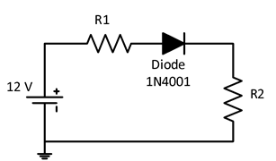
Figure 1
Part B:
- Reverse the polarity of the diode and analyze the circuit. Repeat steps 1) and 2) from Part A.
- Construct the revised circuit in Multisim and repeat steps c) and d) from Part A.
- Tabulate all your data below using appropriate units. Be sure to capture the screen for the measured values.
Table 1:
| Calculated | Measured | |
| Part A: Current (I) | ||
| Part A: Voltage drop across R1(VR1) | ||
| Part A: Voltage drop across R2 (VR2) | ||
| Part B: Current (I) | ||
| Part B: Voltage drop across R1 (VR1) | ||
| Part B: Voltage drop across R2(VR2) |
Review Questions:
- Does the simulation results match the calculated values? If not, explain what causes this difference in the measurements.
- What is the difference between Part A and Part B with respect to the current and voltage drop in the circuit?
Deliverables:
- Follow the template “Lab Report Template” to compile the report and make sure to check the report against the grading rubric below. The template can be found in the “Tools and Templates” link in the navigation center.
- Make sure to include the table, calculations, screenshots of the measurements and the answer to the questions.
 10 years ago
 20
20
Answer(1)![blurred-text]()
Purchase the answer to view it

NOT RATED
 labone_et212.rtf
Bids(1)
other Questions(10)
- Geography Homework
- COM-231 Topic 5 DQ 2
- Because of the close connection between the hypotheses of molecular biology and evolutionary theory, molecular biology's hypotheses and evolutionary theory...
- Birch Company
- continued paper
- What companies initiated recalls within the last 2-3 years and what are their processes for recalls ?
- discrete math homework in mcgraw hill connect
- For Essays Guru
- inclass activity 2
- See attached