

Demodulator circuit
 helpformoney
Watch video entitled “Module 3 – FM Demodulator Circuits in MultiSIM”
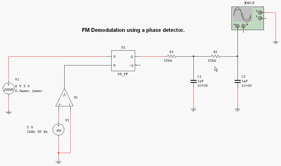
2. Construct the FM demodulator circuit presented in the video with MultiSIM.
3. Capture a screenshot of the stable output waveform.
4. Answer the following questions:
a. What is the purpose of the comparator and flip-flop in the circuit?
b. Why is there a time delay for the output waveform to stabilize?
c. What is the final frequency of the output waveform?
5. Include answers for part 4 and paste the screenshots of part 3 into a Word document entitled “Lab3_StudentID”. Where your student id is substituted in the file name.
6. Upload file “Lab3_StudentID”.
 11 years ago
 45
45
Answer(1)![blurred-text]()

Purchase the answer to view it

 demodulator_circuit_using_multism.docx
Bids(1)
other Questions(10)
- Accounting Class
- exams
- PED 212 Week 1 DQ 2 ( Critical Thinking ) ~ ( Latest Syllabus - Updated Jan, 2015 - Perfect Tutorial - Scored 100% )
- STR 581 Week 5 Strategic Planning & Implementation DQ's & Assignment A+ Graded
- SCO 402 Contemporary Social Problem Week 3 Complete DQs,Quiz and Assignment A+ Graded
- ACCT 344 Week 2 Homework plus Quiz......................(ACCT 344 Cost Accounting - DeVry)
- Multinational Management/payment negotiable
- ethics and social justice 4
- Assignment 3: LASA 1: Full Sentence Outline
- PSY 320 Week 2 Complete DQ & Assignment (Human Motivation) A+