

Capacitive Circuits lab 3
 dragons
Capacitive Circuits
- Watch the videos
- Week 3 Video Lecture - Multisim Single Frequency Analysis
- Consider the circuit below:
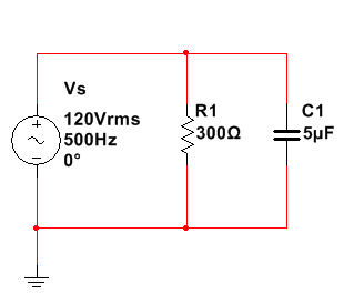
For the circuit above, determine the following (express all answers in phasor form):
- XC
- Zeq
- IT
- R1
- IC1
- Construct the circuit with MultiSIM using a 5% tolerance for the resistor and the capacitor. Adjust the frequency according to the table below and obtain measurements from MultiSIM using AC Analysis and express in polar form.
Frequency IT IR1 IC1 100 Hz 500 Hz 1000 Hz 1500 Hz 10000 Hz 20000 Hz - Discuss the following:
- Describe the relationship between the frequency and IT.
- What effect does frequency have on Zeq?
- How could the circuit be modified to bring the phase angle closer to 0○?
- How could the circuit be modified to bring the phase angle closer to -90○?
Include all calculations, screenshots of measurements, the table results of part 3 and the answers to parts 2 and 4 in a word processing document and submit as EE115W3LabYourGID.docx, or an equivalent word processing file extension.
LAB TEMPLATE BELOW
Introduction:
Write one to two paragraphs about the Lab. Explain the following information for this lab:
§ What are the goals to achieve in the lab?
§ What are the expectations of the lab?
§ How will you be implementing this lab?
§ What will you try to measure?
Equipment/Components:
List the type of equipment or components that you will be using? Where will you find these components? How will you use these components in Multisim/VHDL? Explain any adjustments required such as tolerances.
Procedure:
Briefly describe how you will approach the problem and try to solve the lab, describe and explain any techniques/rules/laws/principles you would use. Outline each step of the process.
Circuit design:
Take a screenshot of the circuit/logic from Multisim/VHDL as asked in the lab assignment before you run the circuit and paste it here in your report.
Execution/Results:
Run the circuit in Multisim/VHDL and copy/paste the results from the simulation including any readings, plots or graphs.
Copy/Paste the screenshots for all the measurements required in the lab here. Be sure to add a title and explain what each of the screenshots represent.
Analysis:
Analyze the results obtained from Multisim/VHDL and compare those to your calculated results (if required).
Answer the following questions:
§ What did you discover/confirm?
§ Use tables and diagrams to record results.
§ Compare calculations with the measured values.
§ Analyze your results.
Explain if your simulation is correct or incorrect and why. If the results are confirmed, then your measurements are correct. If they are not confirmed, explain what the problem is. You will need to discuss how to troubleshoot the circuit to achieve the correct results.
Conclusion:
Summarize the entire lab in 1 to 2 paragraphs with the results and analysis in mind.
Answer any questions asked in the lab assignment here.
Cite any sources that you may use in your report.
ALL THIS NEEDS TO BE DONE AS 1 DOCUMENT.
 10 years ago
 20
20
Purchase the answer to view it

 lab_on_capacitive_reactance.docx
- Advanced Accounting II
- BUSINESS ETHICS/ FORD PINTO CASE
- homework
- ECOM 210 Fundamentals of E-Commerce Week 7 Discussions Devry
- ECOM 210 Fundamentals of E-Commerce Complete Course Week 1 to 8 Devry
- ECOM 210 Fundamentals of E-Commerce Week 4 DQ 1 Business to Business Devry
- COMMUNITY ENRICHMENT
- writing 1 page essay to teacher explaining why i always come late to the class !
- Macroeconomics Homework Assignments
- Economic Assignment : Long-Term Investment Decisions